Welcome to the Software
Telink Position Solution supports AOD/AOD features defined in Core 5.1. Client device is hereinafter referred to as “the LE radio that we want to get direction information”. Server device is hereinafter referred to as “the LE radio that set as the basepoint of the direction information”. Client device can get its direction information for a server device though AOA/AOD method. Using direction information from several server devices and profile-level information giving their locations, a client radio can calculate its own position.
Telink position Solution can provide estimated angle by its embedded MCU, provide 3 reference designs of antenna array, including PCB antenna.
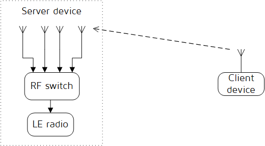
Client device can make its angle of arrival (AoA) information available to server device by transmitting direction finding enabled packets using a single antenna.
Server device, consisting of an RF switch and antenna array, switches antennae while receiving those packets and captures IQ samples. The IQ samples can be used to calculate the phase difference in the radio signal received using different elements of the antenna array, which in turn can be used to estimate angle.
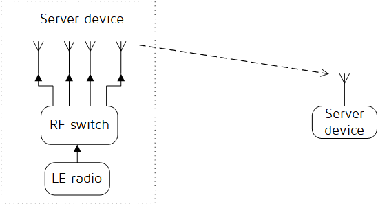
Client device, consisting of an RF switch and antenna array, can make its angle of departure (AoD) detectable by transmitting direction finding enabled packets, switching antennae during transmission.
Client device, consisting of an RF switch and antenna array, can make its angle of departure (AoD) detectable by transmitting direction finding enabled packets, switching antennae during transmission.

Telink Position Solution supports packet format specified for AOA and AOD feature: consisting of Preamble, Access-Address, PDU, CRC (Cyclic Redundancy Check) and Constant Tone Extension. The Header in PDU contains controlling information of AOA AOD.
Constant Tone Extension is specified for AOA AOD feature. The Constant Tone Extension has a variable length; it is at least 16 µs and not greater than 160 µs.
The first 4 µs of the Constant Tone Extension are termed as the guard period and the next 8 µs are termed as the reference period. After the reference period, the constant Tone Extension consists of a sequence of alternating switch slots and sample slots, each either 1 µs or 2 µs long as specified by the Host. The structure of the Constant Tone Extension is shown in the figure below.
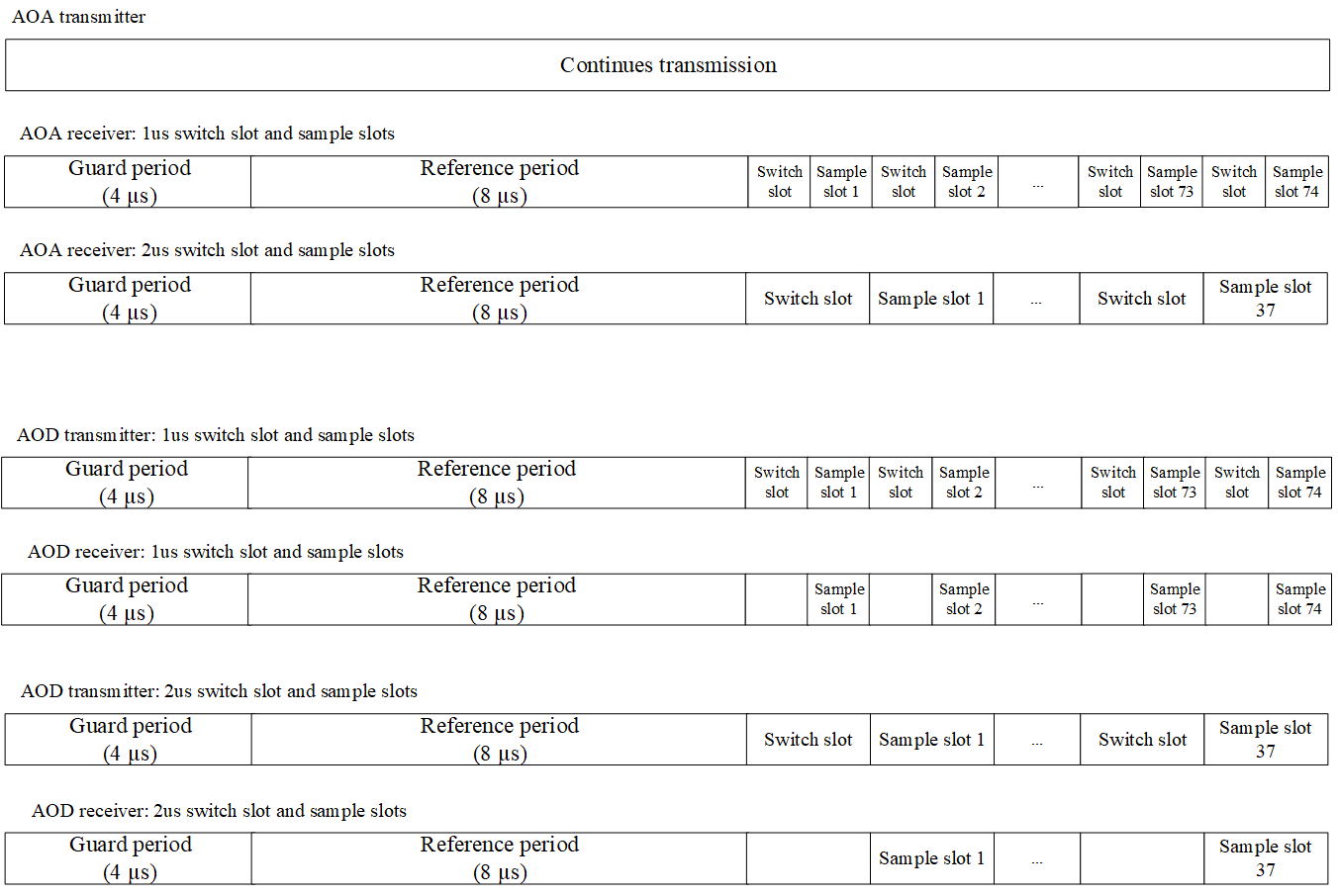
The device switches between the antennas either while receiving the AoA Constant Tone Extension or while transmitting the AoD Constant Tone Extension. The switching takes place during time periods called switch slots. The first 4 µs of the Constant Tone Extension are termed as the protection period and the next 8 µs are termed as the reference period. The receiving Link Layer captures IQ samples during the reference period and during time periods are called sample slots.
The first antenna in the pattern will be used during the reference period. The second antenna in the pattern will be used during the first sample slot, the third antenna during the second sample slot, and so on. The same antenna ID may appear more than once in the pattern. The antenna in use will only be changed during the protection period and switch slots.
When receiving a packet that contains an AoD Constant Tone Extension, the receiver does not need to switch antennas.
When receiving a packet that contains an AoA Constant Tone Extension, the receiver performs antenna switching at the rate and follows the switching pattern configured by the Host.
In both cases, the receiver takes an IQ sample each microsecond during the reference period and an IQ sample each sample slot (thus there will be 8 reference IQ samples). For 2 µs slots, there are up to 37 IQ samples; for 1 µs slots, there are up to 74 IQ samples. The Controller reports the IQ samples to the Host. The receiver samples the entire Constant Tone Extension, irrespective of length, unless it will conflict with other activities.
The receiver measure the RSSI of received packets on the antenna used for receiving the body of the packet (in both cases excluding any Constant Tone Extension).
We tested chip 8278 according to spec “RF-PHY.TS.5.1.1”. The chip 8278 passes all AOA/AOD test cases. Here are some details about these test cases.
The chip 8278 implements 3 GPIO ports to control PA switch. The switch pattern is configurable by software. The 8278 supports up to 8 antennas, 16 non-cycle switches.
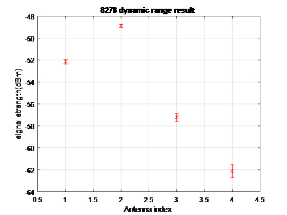
In order to implement high order algorithm such as MUSIC, the IQ samples shall show different amplitude corresponding to the received signal strength. The test case in Spec. is transmit -52,-49,-57 and -62dBm signal to Antenna 1, 2, 3 and 4. The Spec. requires MEAN ANT4 < MEAN ANT3 < MEAN ANT 1 < MEAN ANT 2. The ‘MEAN ANT n’ is IQ samples amplitude mean value of antenna n.
Chip 8278 outputs IQ samples with 8 bit precision. The figure shows the mean and STD. The value of IQ sample from different ports sample by sample, are normalized by the reference signal. The resolution of amplitude is less than 1dB.
In order to calculate phase difference of signal from different antennas to derive angle, the phase of same antenna at different time shall be coherent, and the phase difference from different antennas at different time shall be coherent. See section 5.2 of Core 5.1 for requirement details.
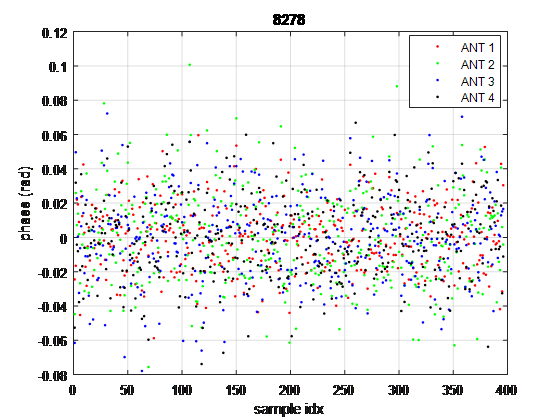
Use power divider to transmit signal to 4 ports of chip 8278, all packet attached with 160µs CW, calibrated cable difference and power divider difference, calibrated initial phase difference with reference signal. The spec requires phase variation (v-MRP) shall be less than 0.52 for same antenna, and phase variation (MRPD) shall be less than 1.125 between different antennas. The STD. value of phase from different ports across packets collected by 8278 are below 0.025 rad. The figure below is the phase of IQ samples from 4 ports.
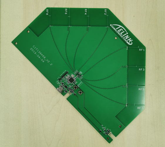
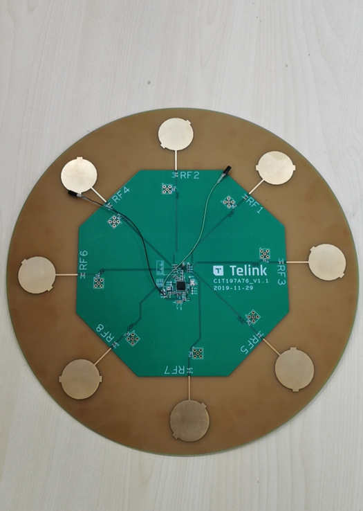
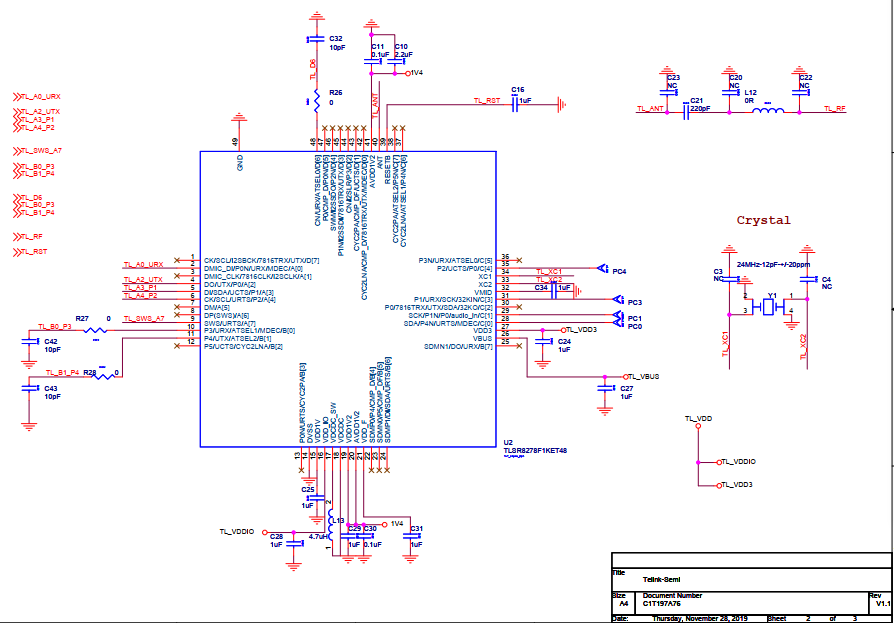
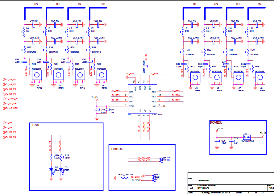
There are 3 selections of reference design, the reference design 1 is for board on the wall and the reference design 2 is for board on the ceiling, the reference design 3 uses PCB antennas as replacement of external antennas in reference design 2.
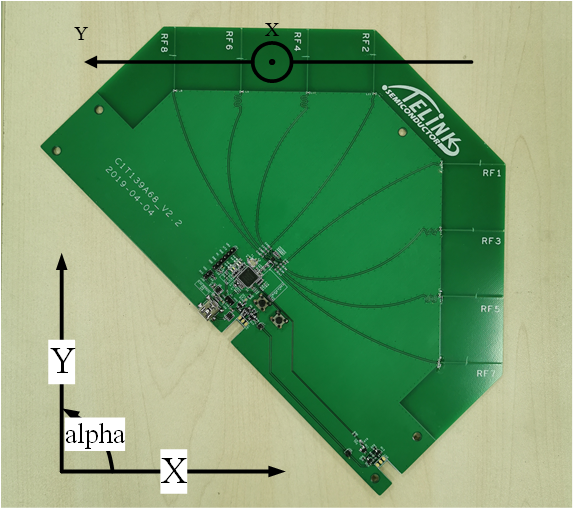
The reference board design 1 is shown in Figure 4.1. The Figure 4.2 shows the illustration of angle. The X axis points to 0 degree while the Y axis points to 90 degree.
The reference board 2 design is show in Figure 4.3 and the illustration of angle see Figure 4.4. Set RF8-RF1 as x axis pointing to 0 degree while taking RF5-RF4 as y axis pointing to 90 degree.

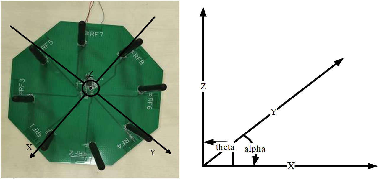
The reference board 3 design is show in Figure 4.5 and the illustration of angle is the same as reference board 2.
For convenience of customer, we provide an API for calculating angles and raw data, so that customers can choose to use our API (with our provided algorithms) to obtain the input angles directly or to develop their own algorithms for calculating angles from raw data. We also provide demos to help customers demonstrate and validate the functionality of AOA or AOD. Customers can access the corresponding SDK and Tscript tools via the links below.
SDK: http://wiki.telink-semi.cn/tools_and_sdk/Driver/telink_b85m_driver_sdk.zip
Tscript: http://wiki.telink-semi.cn/tools_and_sdk/BLE/827x_AOA_AOD_Solution.zip
At present we put the interfaces for the AOA/AOD transceiver configuration in rf_drv.h and rf_drv.c, while the interfaces for the algorithms related to data splitting and angle calculation are in aoa.c and aoa.h. For this reason, customers need to port the corresponding libdriver.a, rf_drv.h and aoa.h to the corresponding project. The user can set up the AOA/AOD function and configure the number of antennas, switching order, sampling interval, etc. by calling the relevant interface in rf_drv.h after RF initialization. The detailed settings can be adjusted according to your needs in the demo section. In addition, aoa.c and aoa.h provide APIs for calculating the angle information from the packet data and the interface for obtaining raw data.
The user can obtain the input angle information by calling unsigned int raw_data_to_angle_no_z(unsigned char *ptr_packet), which returns the value bit plane angle information. The angle information can also be obtained by calling unsigned int raw_data_to_angle_with_z(unsigned char *ptr_packet,unsigned char *temp_theta), which in addition to returning a plane angle, will also output altitude angle information to the temp_theta variable, through which the user can obtain the altitude angle information. Examples are as follows.
unsigned int angle_value;
unsigned char theta_angle;
angle_value = raw_data_to_angle_no_z(&rx_packet[0]);//obtain plane angle information only
angle_value = raw_data_to_angle_with_z(&data_no_amplitude[0],(unsigned char *)&theta_angle);//obtain plane angle and altitude angle
In addition, an interface is provided to obtain raw data, through which the user can obtain the raw IQ data from the receiving end of the packet. The raw data is pre-processed and converted to signed decimal numbers and can then be used by the algorithm to calculate the angle.
unsigned char raw_data[90];
get_raw_data(&raw_data[0],&rx_packet[0],90);
Then raw data is copied to raw_data[0],raw_data[1], raw_data[2] … raw_data[89], which stand real part of IQ0, imaginary part of IQ0, real part of IQ1 …imaginary part of IQ44. User need an unsigned char table which has at least 90 parameters because there are 45 sample data and each data includes real part and imaginary part.
The demo supports the AOA/AOD mode, the customer can choose the mode they use by using the corresponding macro definition. Download the demo program to the reference hardware and the transmitter continuously sends data to the receiver to output the angle. The output angle can be printed via UART, usb to BDT/Tscript or SWS to Tscript. The reference hardware design AOA mode angle output only supports SWS upload to Tscript for output and graphical display.
The demo is currently compatible with the 8278 and 8258 chips, the 8278 will be used as an example when presenting the demo below. The 82xx in the following text can be replaced by 8258 or 8278 depending on the actual situation.
Variable parameters in drivers/82xx/aoa.h:
#define RF_REAL_FREQ 2450 //set TX/RX frequency.here is 2450MHz It defines transmit frequency.
Variable parameters in app.c:
Using 8278 as an example.
/***************Select IO as antenna control pin*************************/
rf_ant_pin_sel_t ant_config =
{
   .antsel0_pin = RF_ANT_SEL0_PD6,
   .antsel1_pin = RF_ANT_SEL1_PB0,
   .antsel2_pin = RF_ANT_SEL2_PB1,
};
The Demo is currently compatible with the 8258 and 8278 and therefore provides a separate set of IOs as antenna control pins.
/***************Choose UART output or Tscript output*************************/
#define BY_TSCRIPT          1
#define BY_UART             2
#define USER_MODE           BY_TSCRIPT
Output angle information using UART or Tscript.
/***************Choose TX or RX*************************/
#define TX      1
#define RX      2

#define RF_TXRX_MODE       RX
It defines board as transmitter or receiver.
/***************Choose AOA or AOD***********************/
#define RF_AOD_EN       0       //0:AOA; 1:AOD
It defines board as AOA or AOD.
#define calibration_no_Z 0 //0: use an algorithm that returns information on altitude angles; 1: use an algorithm that returns information on plane angles onlyIt determines whether the algorithm used processes results with altitude angle information.
The 8258 chip can call the following functions.
/***************Choose antenna quantity and switch sequence***********************/
/**
 * @brief   Take 4 antennas as an example to illustrate the antenna switching sequence
 *          SWITCH_SEQ_MODE0    - antenna index switch sequence 01230123
 *          SWITCH_SEQ_MODE1    - antenna index switch sequence 0123210
 */
         rf_aoa_aod_ant_init(8,&ant_config,SWITCH_SEQ_MODE0);
Note:
- The 8258 only supports two antenna switching sequences, which can be found in the comments of the two antenna switching modes in rf_drv.h
For the 8278 chip, refer to the following settings.
unsigned char antenna_switch_seq[8] = {0,1,2,3,4,5,6,7};
rf_aoa_aod_ant_init(8,&ant_config,SWITCH_SEQ_MODE0,antenna_switch_seq);
The 8278 is more flexible than the 8258 in terms of antenna switching settings. The original way of setting the antenna switching order directly is modified to a table lookup method by using SWITCH_SEQ_MODEx(x= 0,1,2) to set the order of the table lookup; the antenna_switch_seq sets the table content, which is the actual antenna switching order.
/***************************TX/RX frequency**********************
[Brief Description]:RF Frequency. In order to change frequency,please change RF_REAL_FREQ in drivers/82xx/aoa.h
**************************************************************/
#define RF_FREQ         RF_REAL_FREQ-2400    // TX/RX frequency
/***************TX Payload length***************************/
#define TX_PKT_PAYLOAD 0x12It defines the length of the payload part of the packet being sent. Depending on the packet structure, the payload length can be used to check the length and to obtain the offset of the information stored in the packet.
The RF frequency should be verified in aoa.h, by changing RF_REAL_FREQ, but not here.
/***************TX Power***************************/
#if (MCU_CORE_B85)
#define RF_POWER            RF_POWER_P10p46dBm
#elif (MCU_CORE_B87)
#define RF_POWER            RF_POWER_P11p26dBm
#endif
The TX power is defined and this is set according to the chip's energy table.
#define IQ_DATA_8_BIT_EN 0 //0: 20 bit length IQ data is used; 1: 8 bit length IQ data is usedIt defines the length of the IQ data. The 8258 only supports 8 bit length IQ data; the 8278 currently supports 8 bit, 16 bit (low), 16 bit (high) and 20 bit length IQ data. For the 8278 chip, the demo currently only supports 8 bit and 20 bit lengths as examples.
/**************Connect access code*****************/
#define ACCESS_CODE             0xfcaab2c1
It defines ACCESS_CODE.
/**************Script command space*****************/
unsigned char para_buff[commandBuffSize] = {0};
unsigned char temp_para[commandBuffSize] = {0};
When using Tscript for angular display, this space is used for command transmission.
/**************Record tx or rx cnt*****************/
volatile unsigned int rx_cnt=0;//Used to indicate the number of packets received.
volatile unsigned char tx_cnt=0;//The number of packets sent, and the data will be placed in the packet, so that the receiving end can identify the data from different packets.
/*******Store the value of stimer tick ********/
unsigned int tick_now;//Used to store the current tick value to determine the timeout./*******Angle information ********/
unsigned int angle_value; //For storing plane angle information.
unsigned char theta_angle; //Storage of altitude angle results as an output parameter with altitude angle information.These two variables are transferred as results to the Tscript script for use in the upper level display angles.
/*******Obtain space for raw data********/
unsigned char raw_data[90];
This is used to store the raw IQ data used by the algorithm. In the demo, when using 20-bit IQ data, it is first converted to 8-bit data and then stored in raw data.
/*******Upload the results to Tscript ********/
unsigned char trans_buff[136] = {0x00};
unsigned char trans_table[10];
It is for uploading data to Tscript.
/*******Packet receiving data********/
unsigned char  rx_packet[280]  __attribute__ ((aligned (4))) = {0x00};//280 bytes space for IQ data to meet 20 bits lengths, adjustable for different lengths of IQ data.
unsigned char  data_has_amplitude[256]  __attribute__ ((aligned (4))) = {0};
unsigned char  data_no_amplitude[256]  __attribute__ ((aligned (4))) = {0};
Used to store data with and without altitude angle information obtained from rx_packet processing for use by the algorithms that calculate angles.
/*******Antenna angle calibration********/
int phase_rx_angle_cali_angle[8] = {0,-41,82,163,41,-122,122,122};
The calibration for rx_angle in the algorithm.
User_init introduction:
void user_init()
{
        gpio_init(1);
#if (MCU_CORE_B87 || MCU_CORE_B85)
//Used to enable the usb, which can output angle information via the usb.
        usb_set_pin_en();
#endif
//Initialization of the BLE mode, without distinction between tx and rx.
        rf_drv_init(RF_MODE_BLE_1M_NO_PN);
#if(MCU_CORE_B85)
/*************************** Antenna configuration **********************
[Brief Description]:
It mainly configures the number of antennas, controls the pins for antenna switching, and the sequence of antenna switching.
8: stands for enabling 8 antennas, currently 825x chip supports up to 8 antennas. The number of antennas that can be enabled is based on customer requirements.
ant_config: used to control the antenna pins.
SWITCH_SEQ_MODE0: antenna mode switching.
**************************************************************/

rf_aoa_aod_ant_init(8,&ant_config,SWITCH_SEQ_MODE0);
/*************************** IQ sampling configuration**********************
[Brief Description]:
This function is mainly used for IQ data length, sample interval, and sample offset.
IQ_8_BIT_MODE: 8bit length IQ data
SAMPLE_AOA_4US_AOD_CTEINFO_INTERVAL: If AOA, then the 4us sampling interval corresponds to the protocol's 2us as a slot; if it is AOD mode then it is necessary to determine whether it is a 4us sampling interval or a 2us sampling interval according to CTEinfo. This part can be referred to the protocol.
-4: This parameter is used to adjust the position of the initial sampling point, in order to ensure that the sampling point is the optimum point.
**************************************************************/

rf_aoa_aod_sample_init(IQ_8_BIT_MODE,SAMPLE_AOA_4US_AOD_CTEINFO_INTERVAL,-4);
#else

/***************************Antenna configuration**********************
[Brief Description]:
The main configuration is the number of antennas, the pins that control the antenna switching and the order in which the antennas are switched. It is important to note that the 8278 has a different antenna switching sequence than the 8258.
8: stands for enabling 8 antennas, same meaning as 8258.
ant_config: used to control the antenna pins, same meaning as 8258
SWITCH_SEQ_MODE0: table lookup sequence in antenna switching, while in the 8258 it is the actual antenna switching sequence.
antenna_switch_seq: antenna switch order table, to find the antenna that needs to be switched to the corresponding position in the table.
**************************************************************/

rf_aoa_aod_ant_init(8,&ant_config,SWITCH_SEQ_MODE0,antenna_switch_seq);
#if(IQ_DATA_8_BIT_EN)
/***************************IQ sampling configuration**********************
[Brief Description]:same as above.
**************************************************************/

rf_aoa_aod_sample_init(IQ_8_BIT_MODE,SAMPLE_AOA_4US_AOD_CTEINFO_INTERVAL,-4);
#else
rf_aoa_aod_sample_init(IQ_20_BIT_MODE,SAMPLE_AOA_4US_AOD_CTEINFO_INTERVAL,-4);
#endif
#endif

/***************************Algorithm initialization***********************/
#if calibration_no_Z
    init_lookup_table_algorithm_no_Z();
#else
    init_lookup_table_algorithm_with_Z();
#endif

/****************Enable the AOA/AOD function on the transmitter end**************/
#if(RF_TXRX_MODE==TX)
    rf_aoa_aod_set_tx_mode(RF_TX_ACL_AOA_AOD_EN);
    rf_set_power_level_index (RF_POWER);
#elif(RF_TXRX_MODE==RX)
    rf_aoa_aod_set_rx_mode(RF_RX_ACL_AOA_AOD_EN);
#endif

/***************************Ensure the chip is in idle state***********************/
    rf_set_tx_rx_off();
    rf_set_tx_rx_off_auto_mode();

/************Set the transmit and receive frequencies and access code************/
    rf_set_channel(RF_FREQ,0);
    rf_access_code_comm(ACCESS_CODE);

/***********Tscript mode initialisation commands and result space***************/
#if(USER_MODE == BY_TSCRIPT)
    //2.initiate parameter buffer to receive CMD and parameter
    ParaBuf_Init((unsigned int)commandBuff,commandBuffSize,commandBuffCnt);
    //3.initiate result buffer to send the result
    ResuBuf_Init((unsigned int)resultBuff,resultBuffSize,resultBuffCnt);
#endif
}
Main_loop introduction:
The Tx part is mainly to enable the tx mode and then set the corresponding packet interval to send AOA/AOD packets according to the requirements, which can be referred to the following code.
/**********************Tx part ********************/
rf_set_txmode();         //Enable tx mode
    while(1)
    {
        while((unsigned int)(clock_time()-tick_now) < 400000);  //set timeout
        tick_now = clock_time();
        tx_cnt++;
//Send the corresponding packets
#if RF_AOD_EN
        ble_tx_packet_AOD[7]  =tx_cnt;
        rf_tx_pkt (ble_tx_packet_AOD);
#else
        ble_tx_packet_AOA[7]  =tx_cnt;
        rf_tx_pkt (ble_tx_packet_AOA);
#endif
        while(!rf_tx_finish());     //Waif for the end of packet sending
        rf_tx_finish_clear_flag();  //clear interrupt flag
    }
The main tasks in the RX part include: receiving packets, calculating the angle information and outputting the angle information. The output of the angles can be printed by uart or displayed by Tscript. When using the Tscript display, different scripts can be run depending on whether the packet receiving end is connected to the host computer via sigle wire or usb table.
As the RX part is complex, it will be briefly described below in chunks according to function.
/**********************Rx part ********************/
#elif(RF_TXRX_MODE==RX)
      rf_rx_buffer_set((unsigned char*)rx_packet,296, 0);
      rf_set_rxmode ();
      sleep_us(85);
      rx_tick = clock_time();
      //The main function of this part is to set the packet receiving buffer and enable the packet receiving function.

   while(1)
   {
    #if(USER_MODE == BY_TSCRIPT)
         if(is_ParaBuf_HaveData()!= 0)
         {
             ParaBuf_Read(para_buff,commandBuffSize);

             if(para_buff[0] == 0x33)
             {
                 trans_table[1] = RF_FREQ;
                 trans_table[2] = ACCESS_CODE&0xff;
                 trans_table[3] = (ACCESS_CODE>>8)&0xff;
                 trans_table[4] = (ACCESS_CODE>>16)&0xff;
                 trans_table[5] = (ACCESS_CODE>>24)&0xff;
                 trans_table[6] = 2;
    #if(MCU_CORE_B85)
                 trans_table[7] = 1;
    #else
                 trans_table[7] = IQ_DATA_8_BIT_EN;
    #endif
                 trans_table[8] = (TX_PKT_PAYLOAD&0xff);
                 ResuBuf_Write(trans_table, 32);
             }
         }
   }
When using Tscript mode and waiting for the script to give the corresponding command para_buff[0]==0x33, the basic information of the upload program including the frequency of sending and receiving packets, access code, etc. is used by the script to display information or process data.
    if(para_buff[0] == 0x55)
#endif
    {
        while(1)
        {
#if(USER_MODE == BY_TSCRIPT)
        if(is_ParaBuf_HaveData()!= 0)
        {
            ParaBuf_Read(para_buff,commandBuffSize);
            if(para_buff[0] == 0x11)
            {
                while(is_rf_receiving_packet());
                rf_set_tx_rx_off();
                Result_Buff_Clear();
                break;
            }
        }
        }
    }
Get command 0x55 to enter the packet receiving state, determine if the result buffer needs to be cleared, if so wait for the end of the packet receiving. Disable the packet receiving state and clear the result buffer.

From the information in the screenshot until the end of main_loop, this part is mainly about completing the packet receipt and processing the received data to derive the angle information by means of an algorithm.
The raw data from the package will be saved and uploaded to Tscript, where the client can simply verify their algorithm by fetching the raw data through Tscript's script.
Software:
Steps:
a. Change RF_TXRX_MODE in app.c to TX, then use Telink IDE 1.3 build project to generate .\RF_AOA_Demo\RF_AOA_Demo.bin.
b. Connect single antenna board by usb or SW, download TX program.
c. Change RF_TRX_MODE in app.c to RX, then rebuild project to generate a new .\RF_AOA_Demo\RF_AOA_Demo.bin.
d. Connect multi-antenna board by usb or SW, download RX program.
e. Use usb connect multi-antenna RX board to supply power and communicate, then change BDT to usb log mode by View -> usb log as shown in the figure below.

f. Open Log windows. Then user can see input angle once receive AOA packets. Make sure print it out if use print function in program, or program will come out unknown mistake.

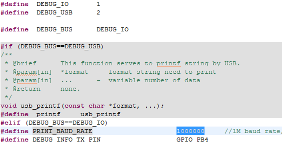
g. If user want to use UART to print, there are some definition need to be changed in drivers/8258/ printf.h. Change DEBUG_BUS as DEBUG_IO, set PRINT_BAUD_RATE and DEBUG_INFO_TX_PIN , then GPIO will emulate UART and print out message with baud rate up to 1000000.
Telink AOA/AOD solution is provided besides Demo. It is used to show AOA/AOD result and collect raw data with referred hardware. The solution includes bin file and debug tool - Tscript. The interface is as follows.
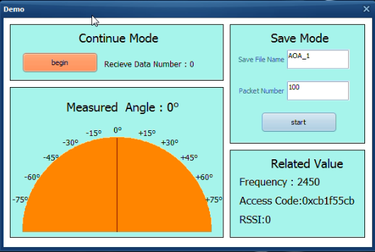
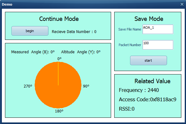
Step1: download specified bin file to the chip. Then connect the board to computer with USB or SWS to power on and communicate. Connect the polygon board to the computer through SWS especially when testing AOA with polygon board since there is no USB on the board.
Step2: open Tscript.exe, double click RF_AutoTest_Kite\AoA.lua as follows. Then the interface is shown as the figure below. Choose AoA_Sniffer_draw_by_sws_V1.4.lua or AoA_Sniffer_draw_by_usb_V1.4.lua according to the different connection mode between the computer and the board.
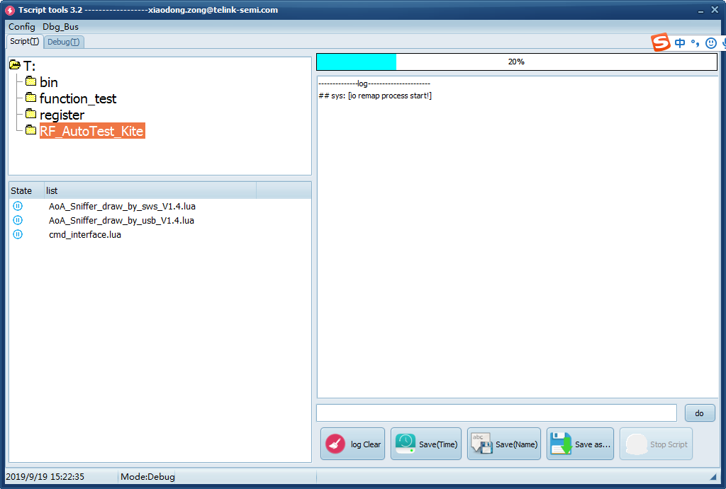
Step3: choose continue mode or save mode to start, these two modes will be introduced in Section 5.3.2 Continue Mode and 5.3.3 Save Mode.
The continue mode is designed to show calculation angle result of inner API. The receive board will continually receive data and calculate angle once receiving AOA/AOD data. After average angle data of fixed window, the result will be shown in the interface and the pointer in table will point to corresponding position. In addition, the received packet number and Frequency/Access Code/RSSI will be shown in the interface as follows. The current interface supports the display of height and plane angles.
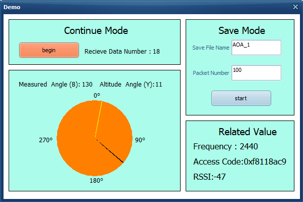
The save mode is designed to collect AOA/AOD raw data. Click start button after inputting Save File Name and Packet Number. Then user can get Save_File_Name.txt that includes decimal sampled IQ value and Save_File_Name_backup.txt that includes hexadecimal source receive data. Users can use other algorithms to process these data or do other experiment.
Save_File_Name.txt will include decimal sampled IQ value of n packets, in which n is the packet number set by user. Each packet contains 45 groups including 90 numbers corresponding to 45 sample point messages. Every group contains two numbers, the first number indicates the real part and the second number represents the imaginary part of sample point. The figure below indicates the slot chart of AoA receiver. In reference period, the chip will sample message every 1µs, obtaining totally 8 groups of number. After that, the chip will sample message in each sample slot, totally 37 groups of number. So each packet includes 37 + 8 = 45 groups for total of 90 numbers.

For example, the above figure indicates one packet of AOA testing containing totally 90 numbers mentioned before. The first line lists 16 numbers sampled in reference period and the sample results are:
-97 – 18i, 2 – 86i, 88 – 14i, 2 + 88i, -90 + 23i, -34 – 97i, 79 – 26i, 41 + 90i
User can also get other 37 sample slot data by this way.

File is located in .\kite_RF_AoA\project\RF_AutoTest_Kite\AutoTest_Report.
The default transmission frequency is 2460 MHz and antenna switch sequence is RF2-> RF4-> RF6-> RF8 for triangle board, RF2 as the primary antenna during reference period, and RF1-> RF2-> RF3-> RF4-> RF5-> RF6-> RF7-> RF8 for polygon board, RF1 as the primary antenna during reference period.
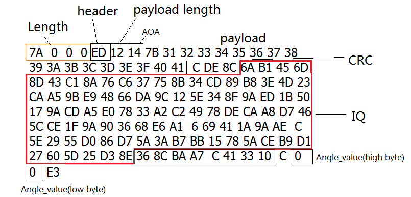
This part will introduce packet format and make an example. Packets format are as bellows:

For example, here is a AOA packet of 2µs switch slot received by triangle board (saved by Tscript). If multiple antenna board is a triangle board, it can be analyzed in following way according to packet format. In save mode of solution that we mentioned before, the receiver will call function to calculate angle and rsquare once receiving a AOA/AOD packet, then put it behind rx_packet. Tscript will read total 130 bytes to get them all.
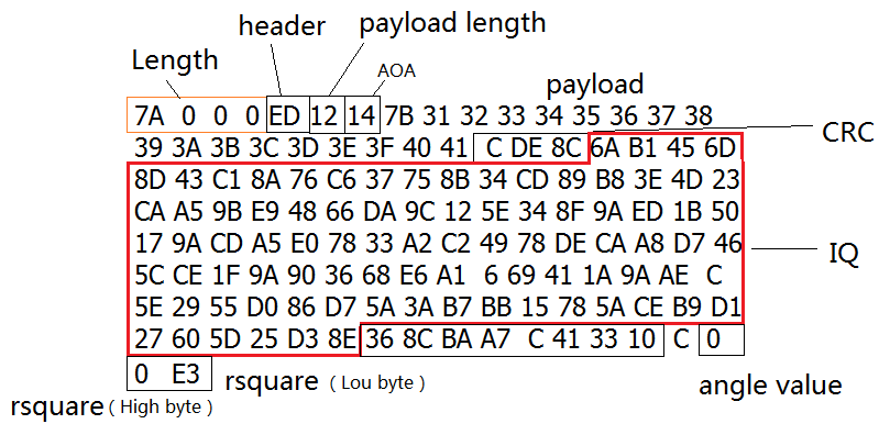
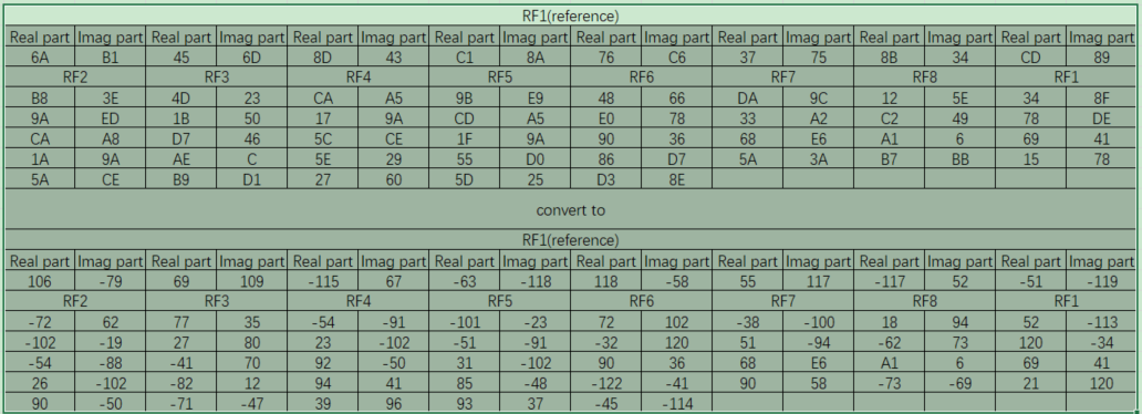
The raw data in rx_packet need to be treated as char variables. So the highest bit is sign bit and lower 7 bits are data bits. They can be transferred to decimal number in standard method. For example, the raw data in the example can be converted as the figure below. The antenna switch sequence is RF2-> RF4 -> RF6 -> RF8.
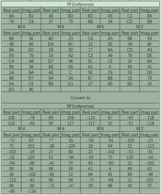
To make another example, here is a AOA packet of 2µs switch slot received by polygon board (saved by Tscript), it can be analyzed in following way according to packet format. In save mode of solution that we mentioned before, receiver will call function to calculate angle once receiving a AOA/AOD packet, then put it behind rx_ packet. Tscript will read total 130 bytes to get them all.
The raw data in the example can be converted as the figure below. The antenna switch sequence is RF1-> RF2-> RF3-> RF4-> RF5-> RF6-> RF7-> RF8.
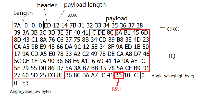
The value of RSSI represents the signal strength of receiving data. We can get the RSSI value from the packet. The data which get from packet minus 110 (D) is RSSI. For example, the data is 0x33, 0x33 minus 110 is -59. So RSSI is -59.
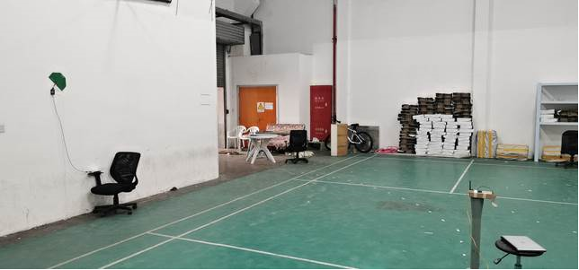
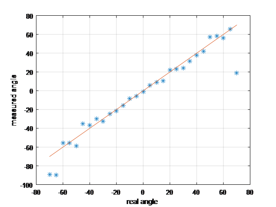
The indoor test environment is shown in the Figure 6.1. The multiple antenna side can switch antenna to transmit or receive constant single tone. It is placed 2 meters high from the ground attached to the wall. At the other side, a single antenna BLE modular is placed 5 meters away from the multiple antenna side. It is tested by 5 degrees step. The result is shown in Figure 6.2.
 {height=400px}
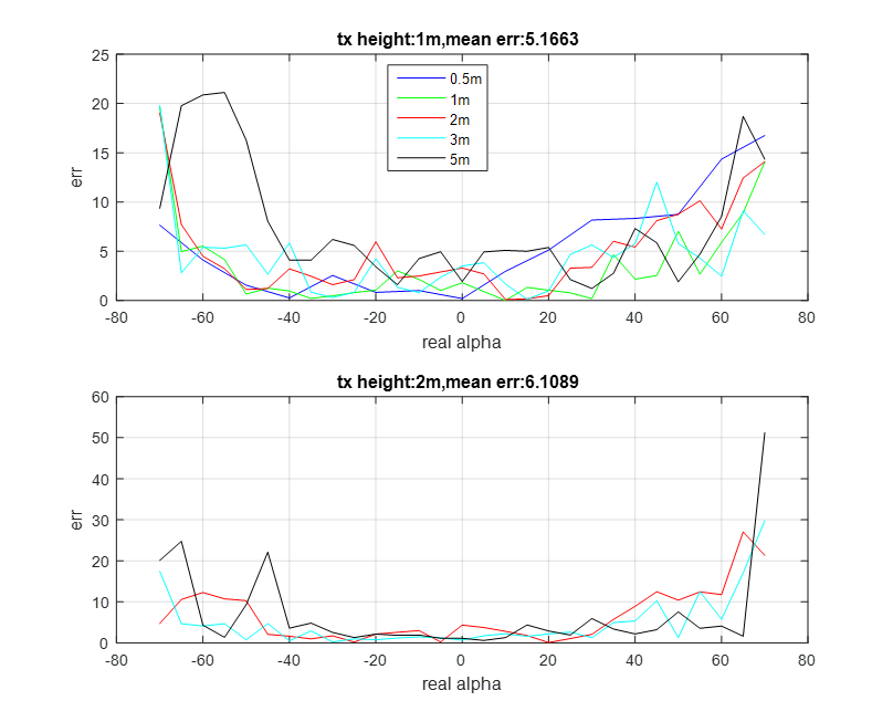
The following figure is the test result for various scenarios which indicates the mean of absolute value of error versus real angle. The height of reference board 1 is 1 or 2 meters and the height of single antenna BLE module is 1 meter. The distance from wall to the single antenna dongle is 0.5, 1, 2, 3 or 5 meters respectively following the below test.
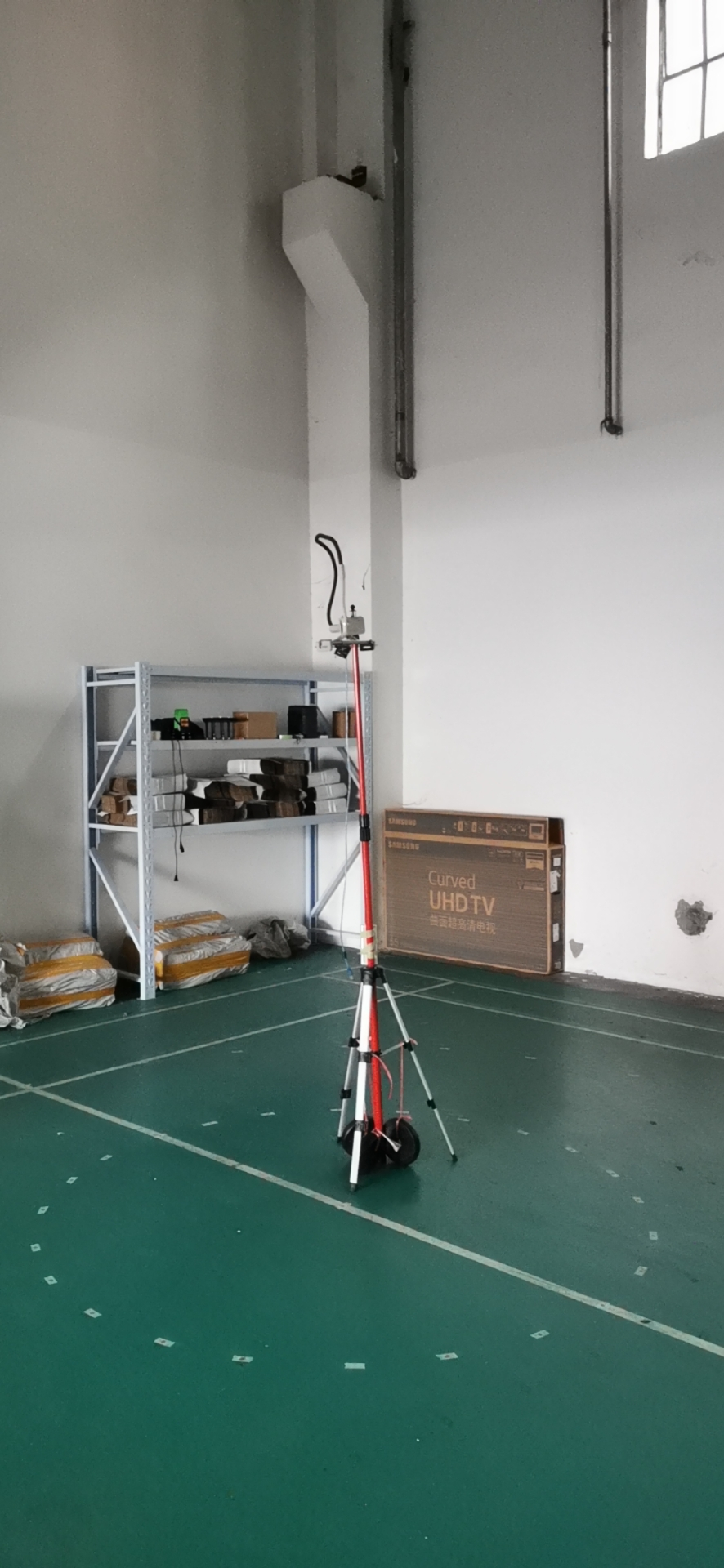
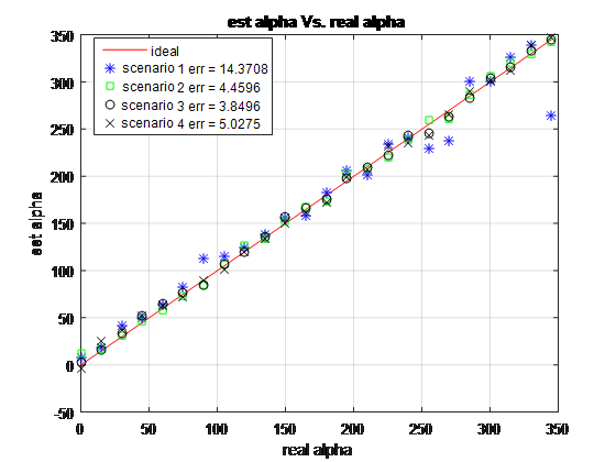
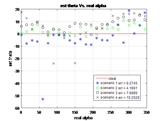
The indoor test environment is shown in the Figure 6.4. The multiple antenna side can switch antenna to transmit or receive constant tone extension. It is hanging on the bracket which is 1.8 meter high. The other side is a single antenna BLE modular, placed on the floor or 0.9 meter high marked as H, 1 or 2 meters far from the bracket marked as D. It is tested by 5 degrees step. The result is shown in Figure 6.5 and Figure 6.6.
Scenario 1: D = 1, H = 0;
Scenario 2: D = 2, H = 0;
Scenario 3: D = 1, H = 0.9;
Scenario 4: D = 2, H = 0.9.
The angle of alpha and theta is measured simultaneously.
 {height=800px}
 {height=400px}
 {height=400px}
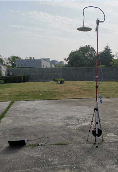
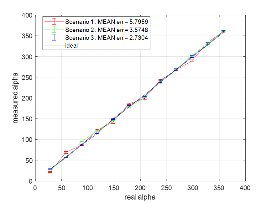
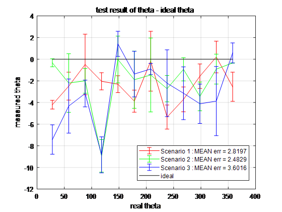
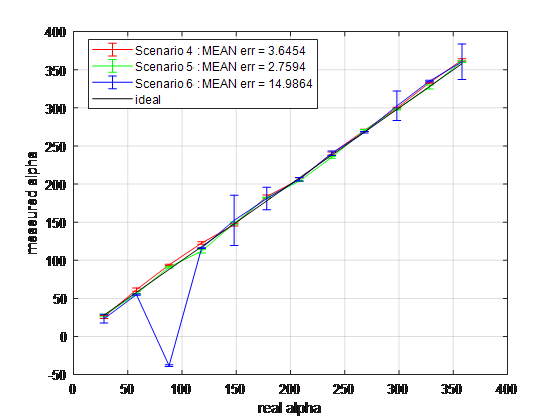
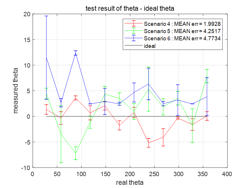
The test environment is shown in the Figure 6.7. The multiple antenna side can switch antenna to transmit or receive constant tone extension. It is hanging on the bracket which is 2.5 meter high. The other side is a single antenna BLE modular, placed on the floor or 1.0 meter high marked as H, 1 or 2 meters far from the bracket marked as D. It is tested by 5 degrees step. The result is shown in Figure 6.8 to Figure 6.11.
Scenario 1: D = 1, H = 0;
Scenario 2: D = 2, H = 0;
Scenario 3: D = 3, H = 0;
Scenario 4: D = 1, H = 1;
Scenario 5: D = 2, H = 1;
Scenario 6: D = 3, H = 1;
The angle of alpha and theta is measured simultaneously.
 {height=400px}
 {height=400px}
 {height=400px}
 {height=400px}
Published by
Telink Semiconductor
Bldg 3, 1500 Zuchongzhi Rd,
Zhangjiang Hi-Tech Park, Shanghai, China
© Telink Semiconductor
All Rights Reserved
Legal Disclaimer
This document is provided as-is. Telink Semiconductor reserves the right to make improvements without further notice to this document or any products herein. This document may contain technical inaccuracies or typographical errors. Telink Semiconductor disclaims any and all liability for any errors, inaccuracies or incompleteness contained herein.
Copyright © 2022 Telink Semiconductor (Shanghai) Co., Ltd.
Information
For further information on the technology, product and business term, please contact Telink Semiconductor Company www.telink-semi.com
For sales or technical support, please send email to the address of:
Version Changes
V1.0.0 Initial release.
V1.1.0 Updated section 3.
V1.2.0 Updated section 4.3.1 and 4.3.3.
V1.3.0 Updated chapter 4.
V1.4.0 Updated chapter 3.
V1.5.0 Updated RSSI; updated ANT switch sequence.
V1.6.0 Updated reference design 3.
V1.7.0 Updated 8278 chips.
V1.8.0 Updated demo.

Login (Email)
Password


The new password
Confirm password