
欢迎使用 软件

This document provides comprehensive guidance on the Telink Matter solution, which includes to/uploads/zip/20240207143629BEC5G/pics such as environment setup, Matter device firmware building and flashing, Border Router setup (including RCP building and flashing), building and usage of chip-tool, etc.
Telink Matter solution is compatible with the following ecosystems:
 Apple Home (iOS)
 Google Home (iOS/Android)
 Amazon Alexa (iOS/Android)
 Samsung Smart Things (iOS/Android)
Apple (iOS): When a Matter device is added to the Apple Home or other ecosystem Home app that utilizes Apple Home APIs, two fabrics are added: one for the Home app and the other for the Apple keychain. To completely remove a device, users need to manually remove device (fabric 1) from the Apple keychain via the Apple settings menu and also remove the device (fabric 2) from the Home app.
Google: Please refer to the official list of unsupported features.
Amazon: Alexa integration requires the rotation device ID, which is already enabled by default in the Telink Matter solution. Additionally, it requires Thread Networks scaning during commissioning (BLE session). To accommodate this requirement, Thread Networks pre-scanning is performed before starting BLE due to the limitation of non-cuncurrent mode.
Samsung: Compatibility with Samsung devices depend on the OS being used. It inherits Apple/Google limitations, as it operates through OS APIs.
CSA: Telink is a dedicated member of the CSA and is committed to the Matter connectivity standard. Telink aims to enhance compatibility across smart home devices. Several end-products built on Telink's Matter over Thread solution have successfully secured Matter v1.0 and v1.1 certifications from CSA. You can view our latest Matter v1.1 certification here:
CSA Matter v1.1 Certification for Telink TLSR9218.
Google: Telink is an approved vendor for Matter v1.0 in Google Home with the Lighting app. All related information can be found at Google's Developer Center.
Amazon: our Lighting app has passed the Amazon MSS (Matter Simple Setup for Thread) certification and will be added as part of Amazon documentation as a certified partner. Therefore, our clients will be able to take advantage of our certified Matter SDK solution and go through a reduced scope certification process.
Please use Telink Matter SDK FFS APID GG8q as a reference APID when creating your FFS Matter product.
To simplify Zephyr environment setup in sections 3.2.1 and 3.2.3, you can use an existing Docker image with a ready-to-use environment.
Run the Docker container (this will take a while to complete the first time):
For latest Matter master branch use the following command:
docker run -it --rm -v $PWD:/host -w /host ghcr.io/project-chip/chip-build-telink:$(wget -q -O - https://raw.githubusercontent.com/project-chip/connectedhomeip/master/.github/workflows/examples-telink.yaml 2> /dev/null | grep chip-build-telink | awk -F: '{print $NF}')For Matter v1.1-branch and v1.0-branch branch use the following command:
docker run -it --rm -v $PWD:/host -w /host connectedhomeip/chip-build-telink:$(wget -q -O - https://raw.githubusercontent.com/project-chip/connectedhomeip/v1.0-branch/.github/workflows/examples-telink.yaml 2> /dev/null | grep chip-build-telink | awk -F: '{print $NF}')You can find the compatible Docker image version in the file:
.github/workflows/examples-telink.yamlSetup Dependencies:
In a new terminal, follow Step 1 in
3.2.2 Matter project setup to set up the necessary dependencies.
Matter Project:
In the Docker container follow Steps 2-4 in
3.2.2 Matter project setup to clone Matter
repository into a clean folder, update submodules for Telink platform and run bootstrap.
Then, follow the instruction in Chapter 4. Matter Firmware to build the firmware.
Before proceeding with the following steps, execute APT update and upgrade:
sudo apt update
sudo apt upgrade
Install Dependencies:
wget https://apt.kitware.com/kitware-archive.sh
sudo bash kitware-archive.sh
sudo apt install --no-install-recommends git cmake ninja-build gperf \
ccache dfu-util device-tree-compiler \
python3-dev python3-pip python3-setuptools python3-tk python3-wheel xz-utils file \
make gcc gcc-multilib g++-multilib libsdl2-dev
Zephyr requires minimum versions of key dependencies, such as
CMake (3.20.0), Python3 (3.6), and Devicetree compiler (1.4.6).
cmake --version
python3 --version
dtc --version
Verify that these dependencies match the required versions on your system. If not, update them manually or switch to a stable APT mirror.
Install West:
pip3 install --user -U west
echo 'export PATH=~/.local/bin:"$PATH"' >> ~/.bashrc
source ~/.bashrc
Make sure ~/.local/bin is on $PATH environment variable.
Get the Zephyr Source Code:
west init ~/zephyrproject
cd ~/zephyrproject
west update
west blobs fetch hal_telink
west zephyr-export
The command west blobs fetch hal_telink is necessary only for Matter master branch and new releases.
Note that fetching the Zephyr source code using
west init ~/zephyrproject and west update may take additional time within mainland China. Moreover, some project may fail to update from foreign
servers.
Consider alternative methods for downloading the latest source code.
Install Additional Python Dependencies for Zephyr:
pip3 install --user -r ~/zephyrproject/zephyr/scripts/requirements.txtSetup Toolchain:
Download Zephyr toolchain (approximately 1~2 GB) into a local directory to enable flashing most boards.
This process may take extra time within mainland China.
For latest master branch use Zephyr SDK v0.16.1:
Minimal SDK:
wget https://github.com/zephyrproject-rtos/sdk-ng/releases/download/v0.16.1/zephyr-sdk-0.16.1_linux-x86_64_minimal.tar.xz
wget -O - https://github.com/zephyrproject-rtos/sdk-ng/releases/download/v0.16.1/sha256.sum | shasum --check --ignore-missing
tar xvf zephyr-sdk-0.16.1_linux-x86_64_minimal.tar.xz
cd zephyr-sdk-0.16.1
./setup.sh -t riscv64-zephyr-elf -h -c
Full SDK:
wget https://github.com/zephyrproject-rtos/sdk-ng/releases/download/v0.16.1/zephyr-sdk-0.16.1_linux-x86_64.tar.xz
wget -O - https://github.com/zephyrproject-rtos/sdk-ng/releases/download/v0.16.1/sha256.sum | shasum --check --ignore-missing
tar xvf zephyr-sdk-0.16.1_linux-x86_64.tar.xz
cd zephyr-sdk-0.16.1
./setup.sh -t riscv64-zephyr-elf -h -c
For v1.1-branch used Zephyr SDK v0.15.2:
For v1.0-branch used Zephyr SDK v0.13.2:
wget https://github.com/zephyrproject-rtos/sdk-ng/releases/download/v0.13.2/zephyr-sdk-0.13.2-linux-x86_64-setup.run
chmod +x zephyr-sdk-0.13.2-linux-x86_64-setup.run
./zephyr-sdk-0.13.2-linux-x86_64-setup.run -- -d ~/.local/zephyr-sdk-0.13.2
You can find the compatible Zephyr SDK version in the file (depends on Matter version):
integrations/docker/images/chip-build-telink/Dockerfileor
integrations/docker/images/stage-2/chip-build-telink/DockerfileDownload Zephyr SDK and install it in recommended path as below:
$HOME/zephyr-sdk[-x.y.z]
$HOME/.local/zephyr-sdk[-x.y.z]
$HOME/.local/opt/zephyr-sdk[-x.y.z]
$HOME/bin/zephyr-sdk[-x.y.z]
/opt/zephyr-sdk[-x.y.z]
/usr/zephyr-sdk[-x.y.z]
/usr/local/zephyr-sdk[-x.y.z]
Where [-x.y.z] is optional text, and can be any text, for example,
-0.16.1.
You cannot move the SDK directory after you have installed it.
Build Hello World Sample
Before proceeding with the custom project setup, please verify that the official Zephyr project configuration is correct using the Hello World sample:
cd ~/zephyrproject/zephyr
west build -p auto -b tlsr9518adk80d samples/hello_world
Build the hello_world example with west build command from the root
of the Zephyr repository.
You can find firmware called zephyr.bin under build/zephyr
directory.
Add Zephyr Environment Script to ~/.bashrc.
Here is the difference between the previously added and the newly added:
+ source ~/zephyrproject/zephyr/zephyr-env.shYou can add the above line using the editor such as vi/vim or execute the
following command in bash:
echo "source ~/zephyrproject/zephyr/zephyr-env.sh" >> ~/.bashrcExecute the following line to activate the updated shell environment
immediately:
source ~/.bashrcAdd Telink Zephyr Remote Repository:
Download the Telink repository locally as the develop branch and update this
branch.
For Matter 1.0-release branch use telink_matter_v1.0-branch!
cd ~/zephyrproject/zephyr
git remote add telink https://github.com/telink-semi/zephyr
git fetch telink develop
git checkout develop
cd ..
west update
west blobs fetch hal_telink
The command west blobs fetch hal_telink is needed only for Matter master branch.
This update may take extra time within mainland China.
For more information, you can refer to https://docs.zephyrproject.org/latest/getting_started/index.html
Setup Dependencies:
sudo apt-get install git gcc g++ pkg-config libssl-dev libdbus-1-dev \
libglib2.0-dev libavahi-client-dev ninja-build python3-venv python3-dev \
python3-pip unzip libgirepository1.0-dev libcairo2-dev libreadline-dev
Clone Matter Project:
Clone the Matter project to your local directory, e.g., /home/${YOUR_USERNAME}/workspace/matter.
git clone https://github.com/project-chip/connectedhomeipThis clone may take extra time within mainland China.
Update Submodules:
Enter the repository root directory and update submodules:
cd ./connectedhomeip
./scripts/checkout_submodules.py --platform telink
Do Bootstrap:
Download and install packages into local for Matter. It usually takes a
long time when running it for the first time.
source ./scripts/activate.sh -p all,telinkThis step will generate an invisible folder called .environment
under the Matter root directory connectedhomeip.
It may cost extra time or encounter failure within mainland China.
INFO: In case of any troubles with Matter build environment you may try the following:
Remove the environment (in the root directory of the Matter project):
rm -rf .environmentRedo the bootstrap once again:
source ./scripts/activate.sh -p all,telinkInstall ZAP CLI Tool (only for the master branch):
According to Matter documentation, ZAP is installed by the bootstrap.sh script.
More information can be found here:
https://github.com/project-chip/connectedhomeip/blob/master/docs/guides/BUILDING.md
Download Toolchain:
Download and unzip the Telink toolchain into your local directory, e.g. ~,
to allow you to flash Zephyr into a Telink board.
wget http://wiki.telink-semi.cn/tools_and_sdk/Tools/IDE/telink_riscv_linux_toolchain.zip
unzip telink_riscv_linux_toolchain.zip
Please note that the download may take several minutes because the zipped file is around hundreds of megabytes. The download may take extra time outside mainland China.
Setup Dependencies:
sudo dpkg --add-architecture i386
sudo apt-get update
sudo apt-get install -y libc6:i386 libncurses5:i386 libstdc++6:i386
Run ICEman.sh Script to Change udev Rules:
The following step 3 and 4 are set up for flashing firmware to
developement boards on the Ubuntu platform.
If you would like to flash firmware on the Windows platform, please igonre
the following setup.
sudo sh ${TELINK_TOOLCHAIN_BASE_DIR}/ice/ICEman.sh${TELINK_TOOLCHAIN_BASE_DIR} is Telink SDK root directory, e.g.
~/telink_riscv_linux_toolchain.
If you encounter issues related to path or permissions, or disconnection
from your Ubuntu host in the current shell, you can enter the above
directory and then try to execute this script:
cd ${TELINK_TOOLCHAIN_BASE_DIR}/ice
source ICEman.sh
Add SPI_burn and ICEman to PATH in ~/.bashrc.
Here is the difference between the previously added and the newly added:
+ export PATH=${TELINK_TOOLCHAIN_BASE_DIR}/flash/bin:"$PATH"
+ export PATH=${TELINK_TOOLCHAIN_BASE_DIR}/ice:"$PATH"The bootloader build is enabled automatically when the CONFIG_CHIP_OTA_REQUESTOR=y is set.
The bootloader configuration file is located at the following path:
connectedhomeip/config/telink/app/bootloader.confThis file contains the following options:
Other MCUBoot configuration options are also allowed in this file. For finest tune please refer to official MCUBoot doc.
For Matter v1.0-branch branch:
telink_matter_v1.0-branch:
...
&flash {
  reg = <0x20000000 0x200000>;

  partitions {
    compatible = "fixed-partitions";
    #address-cells = <1>;
    #size-cells = <1>;

    boot_partition: partition@0 {
      label = "mcuboot";
      reg = <0x00000000 0x10000>;
    };
    slot0_partition: partition@10000 {
      label = "image-0";
      reg = <0x10000 0xE0000>;
    };
    scratch_partition: partition@f0000 {
      label = "image-scratch";
      reg = <0xf0000 0x4000>;
    };
    factory_partition: partition@f4000 {
      label = "factory-data";
      reg = <0xf4000 0x1000>;
    };
    storage_partition: partition@f5000 {
      label = "storage";
      reg = <0xf5000 0xa000>;
    /* region <0xff000 0x1000> is reserved for Telink B91 SDKs data */
    };
    slot1_partition: partition@100000 {
      label = "image-1";
      reg = <0x100000 0xE0000>;
    };
  };
};
...
For Matter v1.1-branch branch:
Implemented as overlay over standard zephyr .dts layout, which is located in the Matter repository
overlay:
...
&flash {
  reg = <0x20000000 0x200000>;

  partitions {
    /delete-node/ partition@0;
    /delete-node/ partition@18000;
    /delete-node/ partition@84000;
    /delete-node/ partition@f0000;
    /delete-node/ partition@f4000;
    boot_partition: partition@0 {
      label = "mcuboot";
      reg = <0x00000000 0x13000>;
    };
    slot0_partition: partition@13000 {
      label = "image-0";
      reg = <0x13000 0xf1000>;
    };
    factory_partition: partition@104000 {
      label = "factory-data";
      reg = <0x104000 0x1000>;
    };
    storage_partition: partition@105000 {
      label = "storage";
      reg = <0x105000 0x8000>;
    };
    slot1_partition: partition@10d000 {
      label = "image-1";
      reg = <0x10d000 0xf1000>;
    };
    /* region <0x1fe000 0x2000> is reserved for Telink B91 SDKs data */
  };
};
...
For the latest Matter master branch:
Implemented as an overlay over standard zephyr .dts layout, which is located in the Matter repository
overlay:
...
&flash {
  reg = <0x20000000 0x200000>;

  partitions {
    /delete-node/ partition@0;
    /delete-node/ partition@20000;
    /delete-node/ partition@88000;
    /delete-node/ partition@f0000;
    /delete-node/ partition@f4000;
    boot_partition: partition@0 {
      label = "mcuboot";
      reg = <0x00000000 0x19000>;
    };
    slot0_partition: partition@19000 {
      label = "image-0";
      reg = <0x19000 0xee000>;
    };
    factory_partition: partition@107000 {
      label = "factory-data";
      reg = <0x107000 0x1000>;
    };
    storage_partition: partition@108000 {
      label = "storage";
      reg = <0x108000 0x8000>;
    };
    slot1_partition: partition@110000 {
      label = "image-1";
      reg = <0x10d000 0xee000>;
    };
    /* region <0x1fe000 0x2000> is reserved for Telink B91 SDKs data */
  };
};
...Basic device configuration is already set via application configuration file.
The basic configuration can be extended via the same configuration file by adding new configurations to the file.
Application configuration file location (relative path):
examples/app/telink/prj.confDevice-to-device communication without a border router is available in case when
one or several devices are configured as FTD (Full Thread Device), for example,
a Light Bulb.
The default configuration for non-sleepy device - is a router. Each router can accept 32 child connections by default.
The amount of child connections is set by the following configuration:
CONFIG_OPENTHREAD_MAX_CHILDREN=1In case of high network load per router device, this configuration may be set to 1 to reduce the amount of children connected to
the parent device.
It is highly recommended to increase the CPU clock to 96MHz if the router mode is planned to use. This can be done by adding the
following configuration to the board overlay file:
overlay:
...
&cpu0 {
    clock-frequency = <96000000>;
};
...
The default configuration of non-sleepy device can be manually changed from router to end device, which will disable the router mode.
Disabling the router mode will reduce the network and CPU load on the device and increase the network stability (avoid packet loss and retransmissions).
This configuration switches the FTD Router device to MTD End device:
CONFIG_CHIP_THREAD_DEVICE_ROLE_END_DEVICE=yIf the FTD End device mode is expected, then the FTD mode can be enabled manually:
CONFIG_OPENTHREAD_FTD=yIn the Matter root folder or /root/chip/ if using Docker image:
Activate Matter environment:
source ./scripts/activate.sh -p all,telinkGo to directory with the example:
cd examples/${app}/telink${app}: all-clusters-app, all-clusters-minimal-app, bridge-app, contact-sensor-app, lighting-app, light-switch-app, lock-app, ota-requestor-app, pump-app, pump-controller-app, resource-monitoring-app, shell, smoke-co-alarm-app, temperature-measurement-app, thermostat, window-app
Remove the previous build if exists:
rm -rf build/Build the example (replace _
example, tlsr9518adk80d or tlsr9528a):
west build -b <build_target>You can find the target built file called zephyr.bin under the
build/zephyr directory.
Flash the example (for the Ubuntu platform):
west flash --eraseIn case of build errors or crashes you might use the Zephyr version which was CI tested against Chip Project master:
Go to https://github.com/project-chip/connectedhomeip/blob/master/integrations/docker/images/stage-2/chip-build-telink/Dockerfile
and look for ZEPHYR_REVISION = ${commit_ID}.
Then use this information to setup Zephyr:
cd ~/zephyrproject/zephyr/
git checkout ${commit_ID}
cd ..
west update
west blobs fetch hal_telinkTo get output from the device, connect UART to the following pins:
| Name | Pin |
|---|---|
| RX | PB3 (pin 15 of J34) |
| TX | PB2 (pin 18 of J34) |
| GND | GND (pin 23 of J50) |
Baud rate: 115200 bits/s
Logging is enabled by default. To disable logging in your application, set this config:
In Matter config/telink/app/zephyr.conf, set CONFIG_SERIAL=n:
    # Logging (set CONFIG_SERIAL to 'y' to enable logging and 'n' to disable logging)
CONFIG_SERIAL=nTo configure the logging level, set the value of the CONFIG_LOG_MAX_LEVEL parameter in Matter config/telink/app/zephyr.conf:
    # Set the actual log level
    # - 0 OFF, logging is turned off
    # - 1 ERROR, maximal level set to LOG_LEVEL_ERR
    # - 2 WARNING, maximal level set to LOG_LEVEL_WRN
    # - 3 INFO, maximal level set to LOG_LEVEL_INFO
    # - 4 DEBUG, maximal level set to LOG_LEVEL_DBG
    CONFIG_LOG_MAX_LEVEL=3
The logging level by default is INFO (information).
It's possible to interact with the device via UART with Unix-like shell commands.
To include Shell in your application, set these two configs:
CONFIG_SHELL=y: # Shell settings
CONFIG_SHELL=yCONFIG_CHIP_LIB_SHELL=y in examples/lighting-app/telink/prj.conf # CHIP shell
CONFIG_CHIP_LIB_SHELL=yNow, after the board starts, you may print help and press Enter in the UART terminal to see a list of available CLI commands.
Every invoked command must be preceded by the matter prefix.
See the following subsections for the description of each Matter-specific
command.
Handles a group of commands that are used to manage the device. You must use
this command together with one of the additional subcommands listed below.
Performs device factory reset, which is a hardware reset preceded by erasing all Matter settings stored in non-volatile memory.
uart:~$ matter device factoryreset
Performing factory reset ...Handles a group of commands that are used to view information about device
onboarding codes. The onboardingcodes command takes one required parameter for
the rendezvous type, and an optional parameter for printing a specific type of
onboarding code.
The full format of the command is:
onboardingcodes none|softap|ble|onnetwork [qrcode|qrcodeurl|manualpairingcode]To print all the onboarding codes:
uart:~$ matter onboardingcodes none
QRCode: MT:W0GU2OTB00KA0648G00
QRCodeUrl: https://project-chip.github.io/connectedhomeip/qrcode.html?data=MT%3AW0GU2OTB00KA0648G00
ManualPairingCode: 34970112332
To print a specific type of onboarding code:
Prints the device onboarding QR code payload. Takes no arguments.
uart:~$ matter onboardingcodes none qrcode
MT:W0GU2OTB00KA0648G00Prints the URL to view the device onboarding QR code
in a web browser. Takes no arguments.
uart:~$ matter onboardingcodes none qrcodeurl
https://project-chip.github.io/connectedhomeip/qrcode.html?data=MT%3AW0GU2OTB00KA0648G00Prints the pairing code for the manual onboarding of a device. Takes no
arguments.
uart:~$ matter onboardingcodes none manualpairingcode
34970112332Handles a group of commands used to view device configuration
information. You can use this command without any subcommand to print all
available configuration data or to add a specific subcommand.
VendorId:        65521 (0xFFF1)
ProductId:       32768 (0x8000)
HardwareVersion: 1 (0x1)
FabricId:
PinCode:         020202021
Discriminator:   f00
DeviceId:
The config command can also take the subcommands listed below.
Prints the PIN code for device setup. Takes no arguments.
uart:~$ matter config pincode
020202021Prints the device setup discriminator. Takes no arguments.
uart:~$ matter config discriminator
f00Prints the vendor ID of the device. Takes no arguments.
uart:~$ matter config vendorid
65521 (0xFFFF1)Prints the product ID of the device. Takes no arguments.
uart:~$ matter config productid
32768 (0x8000)Prints the hardware version of the device. Takes no arguments.
uart:~$ matter config hardwarever
0 (0x0)Handles a group of commands used to control the device Bluetooth LE
transport state. You must use this command together with one of the additional
subcommands listed below.
Prints help information about ble commands group.
uart:~$ matter ble help
  help            Usage: ble <subcommand>
adv Enable or disable advertisement. Usage: ble adv <start|stop|state>Enables Bluetooth LE advertising.
uart:~$ matter ble adv start
Starting BLE advertisingDisables Bluetooth LE advertising.
uart:~$ matter ble adv stop
Stopping BLE advertisingPrints information about the current Bluetooth LE advertising status.
uart:~$ matter ble adv state
BLE advertising is disabledHandles a group of commands used to trigger performing DNS queries. You
must use this command together with one of the additional subcommands listed
below.
Browses for DNS services of _matterc_udp type and prints the received
response. Takes no argument.
uart:~$ matter dns browse
Browsing ...
DNS browse succeeded:
   Hostname: 0E824F0CA6DE309C
   Vendor ID: 9050
   Product ID: 20043
   Long discriminator: 3840
   Device type: 0
   Device name:
   Commissioning mode: 0
   IP addresses:
fd08:b65e:db8e:f9c7:2cc2:2043:1366:3b31Resolves the specified Matter node service given by the \
\
uart:~$ matter dns resolve <fabric-id> <node-id>
Resolving ...
DNS resolve for 000000014A77CBB3-0000000000BC5C01 succeeded:
   IP address: fd08:b65e:db8e:f9c7:8052:1a8e:4dd4:e1f3
Port: 5540Handles a group of Telink commands that are used to manage the device. You must use
this command together with one of the additional subcommands listed below.
Performs board reboot that is hardware reboot calling sys_reboot().
uart:~$ telink reboot
Performing reboot ...Light-switch control commands should be available via Shell interface if the
CONFIG_CHIP_LIB_SHELL=y is set in examples/light-switch-app/telink/prj.conf
Also CONFIG_SHELL=y should be set in config/telink/app/zephyr.conf to use Shell in Matter
To list all the available light-switch commands, call:
uart:~$ matter switch help
  help            Usage: switch <subcommand>
  onoff            Usage: switch onoff <subcommand>
  groups          Usage: switch groups <subcommand>
binding Usage: switch binding <subcommand>The following buttons are available on TLSR9518ADK80D board:
| Name | Function | Description |
|---|---|---|
| Button 1 | Factory reset | Perform factory reset to forget the currently commissioned Thread network and return to a decommissioned state (to activate, press and hold the button for 2 seconds or push the button 3 times (depends on the used branch)) |
| Button 2 | Lighting control | Manually triggers the lighting state (only for lightning-app) |
| LightSwitch control | Triggers the light switch state (only for light-switch-app) | |
| Lock state control | Manually triggers the bolt lock state (only for lock-app) | |
| ContactSensor control | Triggers the contact sensor state (only for contact-sensor-app) | |
| Pump control | Manually triggers the pump state (only for pump-app, pump-controller-app) | |
| Window Open/Toggle move type | Single press manually triggers the Window Covering Open command, double toggles Lift-Tilt move type (only for window-app) | |
| Button 3 | Thread start / Window Close | Commission thread with static credentials and enables the Thread on the device / manually triggers the Window Covering Close command (only for window-app) |
| Button 4 | Start BLE (optional) | Initiate BLE stack and start BLE advertisement |
Note: Some apps will turn on BLE advertising automatically when powered on.
Dependency in the app'sprj.conffrom:# Enable CHIP pairing automatically on application start. CONFIG_CHIP_ENABLE_PAIRING_AUTOSTART=y
Attention to be paid when you have more than one board flashed at the
same time.
If device has no HW Button 1 - Factory reset there is a possibility to perform this action using a power-on sequence.
In the lighting application, the main light (not the indication LED) indicates starting the factory reset procedure by 3-times blinking with an interval of 1 second.
By default, this feature is disabled. To enable it, add the following to prj.conf:
CONFIG_CHIP_ENABLE_POWER_ON_FACTORY_RESET=yThe Red LED indicates current state of Thread network. It is able to be in
the following states:
| State | Description |
|---|---|
| Blinks with short pulses | The device is not commissioned to Thread, Thread is disabled |
| Blinks with frequent pulses | The device is commissioned, Thread enabled. Device is trying to JOIN thread network |
| Blinks with wide pulses | The device commissioned and joined to the Thread network as a CHILD |
The Green LED is used to identify the device. The LED starts blinking when the Identify command of the Identify cluster is received. The command's argument can be used to specify the the effect.
It can be in the following effects:
| Effect | Description |
|---|---|
| Blinks (200 ms on/200 ms off) | Blink (EMBER_ZCL_IDENTIFY_EFFECT_IDENTIFIER_BLINK) |
| Breathe (during 1000 ms) | Breathe (EMBER_ZCL_IDENTIFY_EFFECT_IDENTIFIER_BREATHE) |
| Blinks (50 ms on/950 ms off) | Okay (EMBER_ZCL_IDENTIFY_EFFECT_IDENTIFIER_OKAY) |
| Blinks (1000 ms on/1000 ms off) | Channel Change (EMBER_ZCL_IDENTIFY_EFFECT_IDENTIFIER_CHANNEL_CHANGE) |
| Blinks (950 ms on/50 ms off) | Finish (EMBER_ZCL_IDENTIFY_EFFECT_IDENTIFIER_FINISH_EFFECT) |
| LED off | Stop (EMBER_ZCL_IDENTIFY_EFFECT_IDENTIFIER_STOP_EFFECT) |
By default, only Blue LED is used to show the current state of lightbulb (only for lightning-app).
To get the current state of lightbulb in RGB mode, connect a 3-color LED module to the following pins:
| Name | Pin |
|---|---|
| Red | PE2 (pin 8 of J34) |
| Green | PE0 (pin 5 of J34) |
| Blue | PB4 (pin 20 of J34) |
| GND | GND (pin 24 of J50) |
To enable RGB functionality in your application, set this config:
In Matter examples/lighting-app/telink/include/AppConfig.h, set the define USE_RGB_PWM:
define USE_RGB_PWM 1The White LED shows current state of Contact Sensor, Bolt Lock and Pump.
Short blinks in the Lock app indicate a transition state from Locked to Unlocked and vice versa.
For both Pump apps, the white LED shows the on-off-state of the pump.
Blue LED indicates the current Window Cover Lift position (PWM in range of 0-254).
To indicate the Tilt state in the same way, connect an external LED to the board pin PE0.
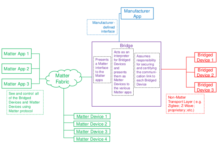
A Bridge serves to allow the use of non-Matter IoT devices (e.g. devices on a Zigbee or Z-Wave net
work, or any other non-Matter connectivity technology) in a Matter Fabric, with the goal of enabling
consumers to continue using these non-Matter devices alongside their Matter devices.
The Telink Bridge Example demonstrates a simple lighting bridge and the use of
dynamic endpoints.
The Bridge device performs the translation between Matter and other protocols allowing Matter nodes
to communicate with Bridged Devices.
A Bridge may also contain native Matter functionality, for example,
it may itself be a Temperature sensor having both Thread and Zigbee connections.
As stated in Matter Specification, this is illustrated in the figure below: the non-Matter devices are exposed as Bridged Devices to
Nodes on the Fabric. The Matter Nodes can communicate with both the (native) Matter devices and the Bridged Devices, thanks to the Bridge, which performs the translation between Matter
and the other protocol.
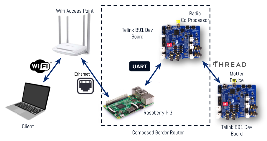
An Open Thread border router is a composed device that consists of two main parts:
Two devices can be used to create RCP device.
In this case, the RCP is an additional TLSR9518ADK80D board (B91 Generic Starter Kit).
Build from the Zephyr project root folder:
1.1 Using DuPount cables:
rm -rf build_ot_coprocessor

west build -b tlsr9518adk80d -d build_ot_coprocessor zephyr/samples/net/openthread/coprocessor -- -DOVERLAY_CONFIG=overlay-rcp.conf
1.2 Using a USB connection:
rm -rf build_ot_coprocessor

west build -b tlsr9518adk80d -d build_ot_coprocessor zephyr/samples/net/openthread/coprocessor -- -DDTC_OVERLAY_FILE="usb.overlay" -DOVERLAY_CONFIG=overlay-rcp-usb-telink.conf
Flash the firmware:
west flash --erase -d build_ot_coprocessorThis option is bases on an additional TLSR9518AGK80D board (B91 Dongle) that can be used instead of the TLSR9518ADK80D board (B91 Generic Starter Kit). It uses only a USB connection with the BR. The dongle must be inserted into the BR.
Build from the Zephyr project root folder:
rm -rf build_ot_coprocessor

west build -b tlsr9518adk80d -d build_ot_coprocessor zephyr/samples/net/openthread/coprocessor -DDTC_OVERLAY_FILE="usb.overlay boards/tlsr9518adk80d-dongle.overlay" -DOVERLAY_CONFIG=overlay-rcp-usb-telink.conf
Flash the firmware:
west flash --erase -d build_ot_coprocessorNote
USB mode requires modifying OTBR_AGENT_OPTS in the RPi image by changing the device port to /dev/ttyACM0, like this:
OTBR_AGENT_OPTS="-I wpan0 -B eth0 spinel+hdlc+uart:///dev/ttyACM0?uart-flow-control trel://
eth0"See Setup BR, point 7.
It can be done in the current image, but a reboot is required after the change.
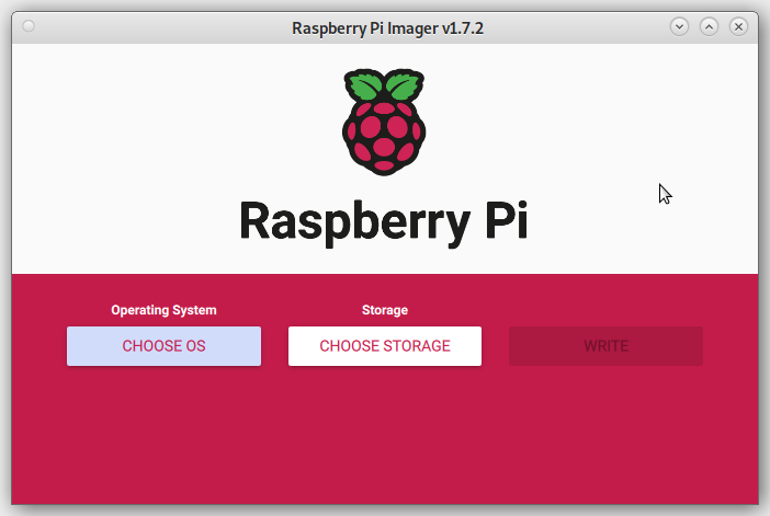
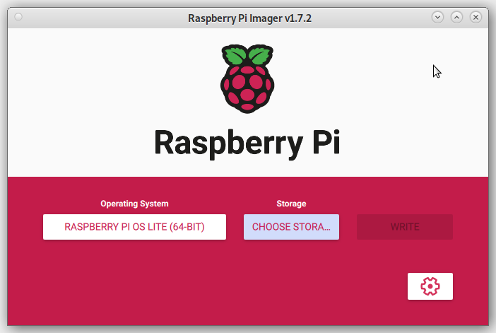
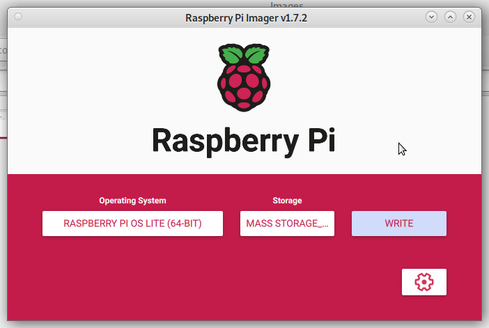
Install Imager:
sudo apt install rpi-imagerInsert your SD card into the PC.
Open Imager and press "CHOOSE OS" button:
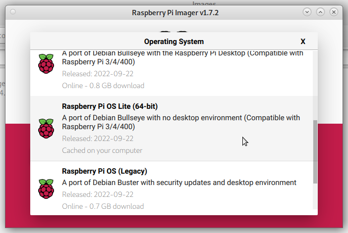
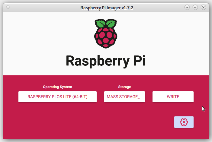
Choose "Raspberry Pi OS (other)" > "Raspberry Pi OS Lite (64-bit)":
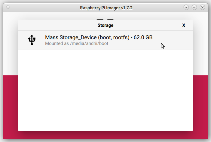
Press the "CHOOSE STORAGE" button and choose your SD card:
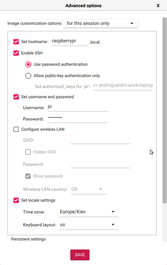
Press the "SETTINGS" button and apply required image configuration:
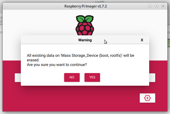
Press "Write":
Confirm that you want to continue writhing.
WARNING: All data from the SD card will be erased.
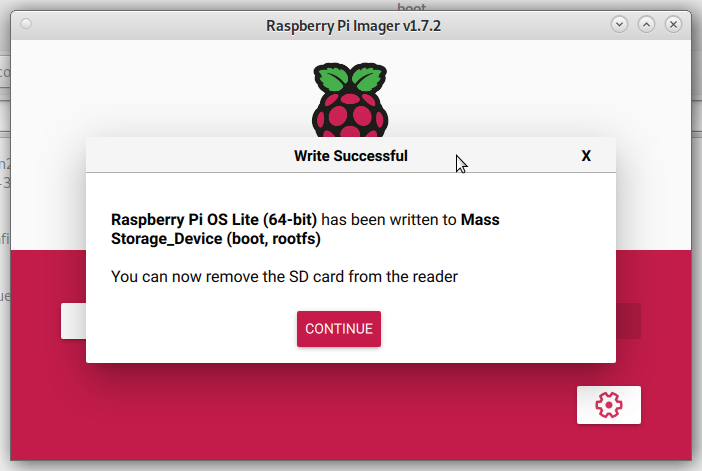
Wait for the write to completion. If everything is ok, you will see the following
message:
WARNING: Before you continue, make sure your configured hardware platform
is connected to the internet using Ethernet.
The bootstrap script disables the platform's Wi-Fi interface, and the setup
script requires internet connectivity to download and install several
packages.
Insert the SD card and attach an Ethernet cable and power supply to the Raspberry Pi.
Check the Raspberry Pi address on your router. Enter an SSH session to your Raspberry Pi
using credentials from the Write image step 6.
Set up the serial port with RTS/CTS flow control. Add the following line to the end of the file
/boot/config.txt
dtoverlay=uart3,ctsrtsInstall required software (Git, NodeJs)
sudo apt update
sudo apt install git npm
Clone the OpenThread Border Router:
git clone https://github.com/openthread/ot-br-posixDo bootstrap:
cd ot-br-posix
./script/bootstrap
Setup:
WEB_GUI=1 INFRA_IF_NAME=eth0 ./script/setupModify /etc/default/otbr-agent file by replacing the default string with
the following difference:
- OTBR_AGENT_OPTS="-I wpan0 -B eth0 spinel+hdlc+uart:///dev/ttyACM0 trel://eth0"
+ OTBR_AGENT_OPTS="-I wpan0 -B eth0 spinel+hdlc+uart:///dev/ttyAMA1?uart-flow-control trel://eth0"
Attach RCP according to the connection map:
| RCP Telink B91 J20 header | Raspberry Pi 4 J8 header |
|---|---|
| TX - PC6 (pin 11) | UART3 RX (pin 29) |
| RX - PC7 (pin 12) | UART3 TX (pin 7) |
| RTS - PC5 (pin 14) | UART3 CTS (pin 31) |
| CTS - PC4 (pin 13) | UART3 RTS (pin 26) |
| GND (e.g., pin 23 of J50 or pin 3 of J56) | GND (e.g., pin 6 or 9) |
Reboot the Raspberry Pi
sudo rebootMore information can be found here: https://openthread.io/guides/border-router/build
Download the binaries
Unzip the rpi_ot_br_posix.iso.zip archive.
Insert the SD card into your PC.
Use "dd" command to copy the image to the SD card:
sudo dd if=<path_to_image> of=<path_to_sd_card_device> bs=4M conv=noerror,sync status=progressExample: (replace 'sdx' with the proper device)
sudo dd if=~/Tmp/rpi_ot_br_posix.iso of=/dev/sdx bs=4M conv=noerror,sync status=progressWARNING: Be cautious when using “dd” with root privileges, as it can potentially brick your system!
Wait for the copy process to finish.
Insert the SD card into Raspberry Pi.
Flash the Telink B91 RCP using zephyr.bin file.
Connect the RCP to the Raspberry Pi.
Plug the Raspberry Pi to a power source.
Wait a few minutes for it to load. It's done.
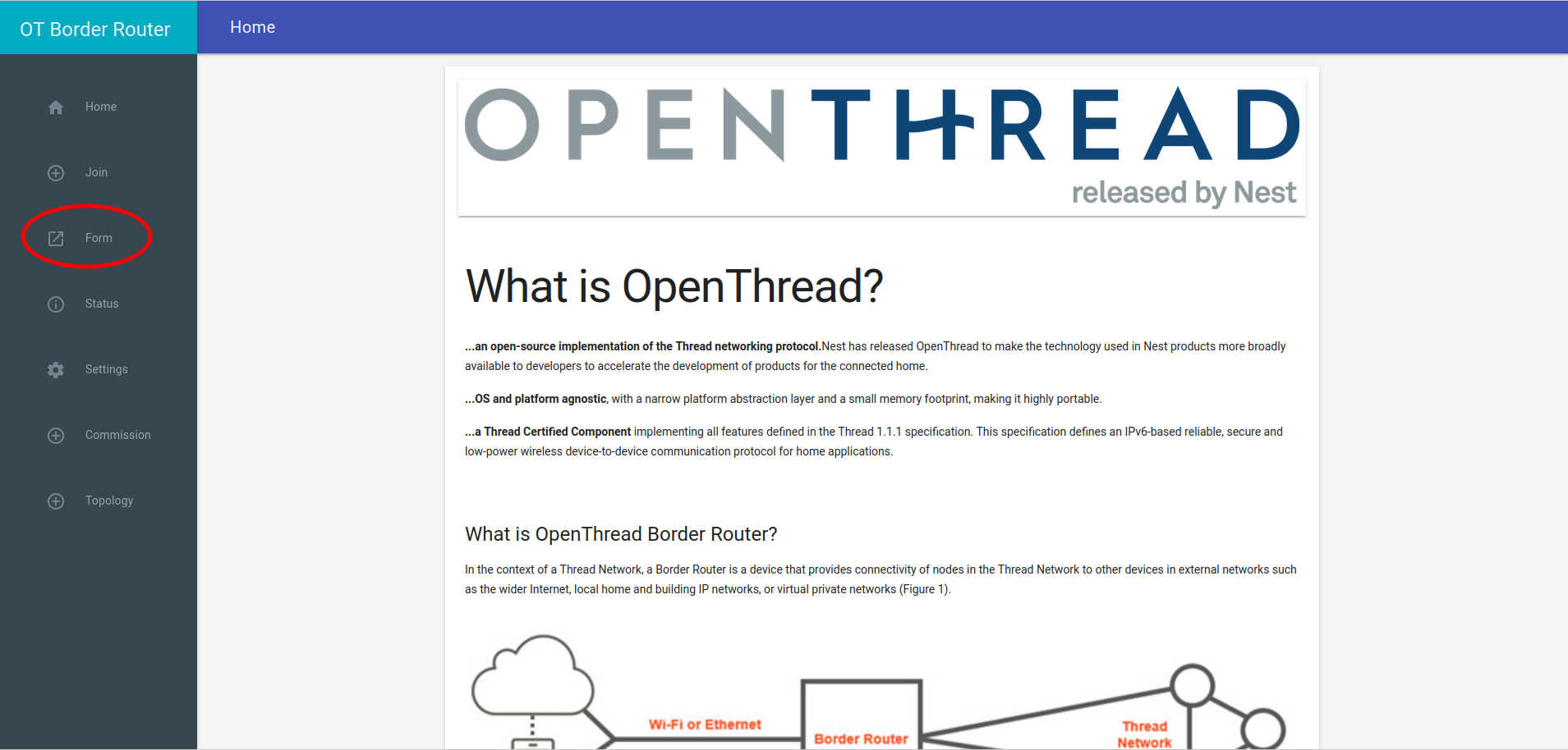
Open your web browser.
In the address bar, type the IP address of your Border Router.
If everything is okay, you should see the Border Router Home page.
Go to the "Form" page:
Enter the desirable Thread credentials. You can leave them default if you prefer.
Click the "Form" button.
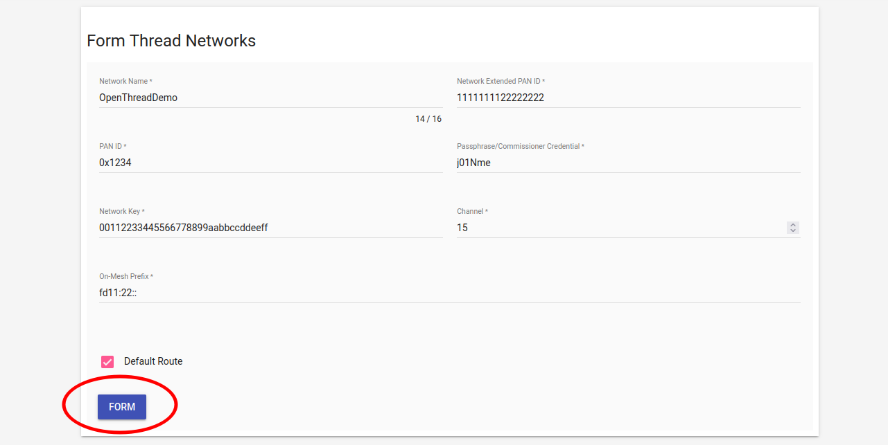
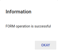
Confirm that you want to form the Thread Network by clocking the "OKAY"
button.

Wait for the "Form operation successful" message.
Connect to the OpenThread Border Router via SSH (default password: raspberry):
ssh pi@${OTBR_IP_ADDRESS}Set the Thread network operational dataset:
sudo ot-ctl dataset set active
0e080000000000010000000300000f35060004001fffe0020811111111222222220708
fd7302e133ca932d051000112233445566778899aabbccddeeff030e4f70656e546872
65616444656d6f010212340410445f2b5ca6f2a93a55ce570a70efeecb0c0402a0fff8
Initialize the Thread network operational dataset:
sudo ot-ctl dataset init activeCommit the Thread network operational dataset:
sudo ot-ctl dataset commit activeBring the interfaces up:
sudo ifconfig wpan0 upStart the Thread network:
sudo ot-ctl thread startConnect to the OpenThread Border Router via SSH (default password: raspberry):
ssh pi@${OTBR_IP_ADDRESS}Retrieve the Thread network operational dataset:
sudo ot-ctl dataset active -xThe output will resemble the following dataset:
0e080000000000010000000300000f35060004001fffe0020811111111222222220708
fd7302e133ca932d051000112233445566778899aabbccddeeff030e4f70656e546872
65616444656d6f010212340410445f2b5ca6f2a93a55ce570a70efeecb0c0402a0fff8
Store this dataset for further commissioning steps.
WARNING: The Thread border router creates a new active dataset on each Form
operation.
Due to the presence of only one full-featured UART port availabe on RPi 3, some additional actions are required:
Disable the console and logging over UART:
Login into RPi via SSH and activate configuration tool:
sudo raspi-configSelect "3 Interface options"
Select "I6 Serial Port"
Close the tool by selecting "Finish"
Switch the BLE chip to use miniUART instead of the full featured UART:
Add the following line to the end of the /boot/config.txt file:
dtoverlay=pi3-miniuart-btReboot the board:
sudo rebootConfigure GPIOs to act as hardware flow control (RTS and CTS):
There are various tools to do that. The tested and working method is described below:
Login to the RPi console and fetch the tool:
git clone https://github.com/mholling/rpirtscts.gitCompile the tool:
cd rpirtscts/
make
Use the tool:
sudo ./rpirtscts onThe output should indicate which pins are used for hardware flow control:
assuming 40-pin GPIO header
Enabling CTS0 and RTS0 on GPIOs 16 and 17
Shut down the board:
sudo haltWait until "activity" (green) light stops flashing and power off the RPi board.
Connect the Telink RCP to 40-pin headder of the RPi:
| RCP Telink B91 J20 header | Raspberry Pi 4 J8 header |
|---|---|
| TX - PC6 (pin 11) | UART RX (pin 10) |
| RX - PC7 (pin 12) | UART TX (pin 8) |
| RTS - PC5 (pin 14) | UART CTS (pin 36) |
| CTS - PC4 (pin 13) | UART RTS (pin 11) |
| GND (e.g., pin 23 of J50 or pin 3 of J56) | GND (e.g., pin 6 or 9) |
For convenience of having all connection at one side of the board, power and ground can be applied via the JTAG connector.
PAY EXTREME ATTENTION TO JTAG PINS NUMBERING. The 1st pin of JTAG is marked with a triangle maker (and a square soldering pad at the bottom).
The round dot and "1 2" numbers refer to J34 pins!
| RCP Telink B91 J5G header | Raspberry Pi 4 J8 header |
|---|---|
| +5V - (pin 8) | +5V - (pin 2) or (pin 4) |
| GND - (pin 9) | GND - (pin 6) ot (pin 9) |
Start the board and log in to the console.
Modify the file: /etc/default/otbr-agent
- OTBR_AGENT_OPTS="-I wpan0 -B eth0 spinel+hdlc+uart:///dev/ttyACM0 trel://eth0"
+ OTBR_AGENT_OPTS="-I wpan0 -B eth0 spinel+hdlc+uart:///dev/ttyAMA0?uart-flow-control trel://eth0"
Reboot the board and try to from a Thread network.
(Not recommended due to stability issues)
With an additional USB->UART converter, it is possible to build an OT Border router with RPi 3.
Prepare the Raspberry PI 3 OT boarder router as described above but DO NOT form a Thread network yet!
Connect the Telink board to a USB dongle:
| RCP Telink B91 J20 header | USB -> UART Dongle |
|---|---|
| TX - PC6 (pin 11) | RX |
| RX - PC7 (pin 12) | TX |
| RTS - PC5 (pin 14) | CTS |
| CTS - PC4 (pin 13) | RTS |
| GND (e.g., pin 23 of J50 or pin 3 of J56) | GND |
Log in to the RPI via SSH and connect the USB dongle.
Check the device file assigned to your dongle:
$ dmesg

usb 1-1.3: new full-speed USB device number 7 using dwc_otg
[ 4112.930175] usb 1-1.3: New USB device found, idVendor=0403, idProduct=6001, bcdDevice= 6.00
[ 4112.930202] usb 1-1.3: New USB device strings: Mfr=1, Product=2, SerialNumber=3
[ 4112.930213] usb 1-1.3: Product: FT232R USB UART
[ 4112.930222] usb 1-1.3: Manufacturer: FTDI
[ 4112.930231] usb 1-1.3: SerialNumber: AQ03MIVH
[ 4112.943040] ftdi_sio 1-1.3:1.0: FTDI USB Serial Device converter detected
[ 4112.943184] usb 1-1.3: Detected FT232RL
[ 4112.944703] usb 1-1.3: FTDI USB Serial Device converter now attached to ttyUSB0
In our case it's ttyUSB0.
Modify the /etc/default/otbr-agent file by replacing the default string with
the following difference:
- OTBR_AGENT_OPTS="-I wpan0 -B eth0 spinel+hdlc+uart:///dev/ttyACM0 trel://eth0"
+ OTBR_AGENT_OPTS="-I wpan0 -B eth0 spinel+hdlc+uart:///dev/ttyUSB0?uart-flow-control trel://eth0"
Replace "ttyUSB0" with the device file you obtained in step 4.
Reboot the board:
sudo rebootWait until the reboot. Now it should be possible to use the border router.
WARNING: Ensure that the chip tool is built on the same commit as the Matter firmware to prevent compatibility issues.
Activate the environment under the Matter project root directory:
source ./scripts/activate.sh -p all,telinkUpdate submodules:
./scripts/checkout_submodules.py --allow-changing-global-git-config --shallow --platform linuxGo to the example folder:
cd examples/chip-toolRemove the previous build if necessary:
rm -rf out/Build:
gn gen out
ninja -C out
the "chip-tool" binary can be located here:
${MATTER_CHIP_TOOL_EXAMPLE_FOLDER}/out/chip-toolFor more information, visit: https://github.com/project-chip/connectedhomeip/blob/master/examples/chip-tool/README.md
Commission the device with the latest active dataset. See the
Get active dataset section under the Border router
heading:
./chip-tool pairing ble-thread ${NODE_ID} hex:${DATASET} ${PIN_CODE} ${DISCRIMINATOR}NODE_ID can be any non-zero value that has not been used before. It acts as a handler for other "chip-tool" operations referring to a specific Matter device.
DATASETs are regenerated by the Thread border router when new Thread
networks are formed.
They might slightly differ in the middle of the hex string so DO NOT use
the dataset from the following command directly.
If you forget it, refer back to the Get active dataset section and replace DATASET with the current dataset.
Example:
$ ./chip-tool pairing ble-thread 1234
hex:0e080000000000010000000300000f35060004001fffe002081111111122222222070
8fd61f77bd3df233e051000112233445566778899aabbccddeeff030e4f70656e54687265
616444656d6f010212340410445f2b5ca6f2a93a55ce570a70efeecb0c0402a0fff8
20202021 3840
Commission might take some time. If it's successful, you should
see the following message:
Device commissioning completed with successIn case of failures, the device configuration can be cleared with the following command:
sudo rm -rf /tmp/chip_*It's highly recommended to use a BLE 5.0 HCI controller on the host machine running "chip-tool".
To check HCI version:
hciconfig -aYou can commission an example Matter device without BLE connectivity, relying only on Thread.
Ensure that the OTBR (Open Thread Border Router) is up and running and network has been formed:
Refer to the Border Router section of this guide for more details.
Join the Matter Demo device using Button_3 (Joining Thread with hardcoded credentials):
Confirm that the red LED blinks with short pauses:
Beside the LED indication, you can verify the device has joined using OTBR Web GUI (Topology).
Use "chip-tool" for "onnetwork" commissioning:
./chip-tool pairing onnetwork ${NODE_ID) ${PIN_CODE}Example:
./chip-tool pairing onnetwork 1001 20202021PIN_CODE can be obtained from Demo Device logs.
See the Matter Firmware section of this guide for more details.
Example logs:
I: 536 [DL]Device Configuration:
I: 542 [DL]  Serial Number: 11223344556677889900
I: 547 [DL]  Vendor Id: 65521 (0xFFF1)
I: 550 [DL]  Product Id: 32772 (0x8004)
I: 554 [DL]  Product Name: not-specified
I: 560 [DL]  Hardware Version: 0
I: 566 [DL]  Setup Pin Code (0 for UNKNOWN/ERROR): 20202021
I: 573 [DL]  Setup Discriminator (0xFFFF for UNKNOWN/ERROR): 3840 (0xF00)
I: 583 [DL]  Manufacturing Date: (not set)
I: 660 [DL]  Device Type: 65535 (0xFFFF)
PIN_CODE == 20202021 in this case.
Example:
$ ping6 fd11:22:0:0:7b6a:4020:5b68:b403
PING fd11:22:0:0:7b6a:4020:5b68:b403(fd11:22::7b6a:4020:5b68:b403) 56 data bytes
64 bytes from fd11:22::7b6a:4020:5b68:b403: icmp_seq=1 ttl=64 time=0.540 ms
64 bytes from fd11:22::7b6a:4020:5b68:b403: icmp_seq=2 ttl=64 time=0.601 ms
64 bytes from fd11:22::7b6a:4020:5b68:b403: icmp_seq=3 ttl=64 time=0.587 ms
If the ping fails, proceed to step 4.
To retrieve the IP address of the Matter example device, rebuild and reflash the firmware with the Zephyr console enabled (refer to the Matter Firmware section for more details).
In the Zephyr console:
uart:~$  ot ipaddr

fd11:22:0:0:1092:f710:43ba:bdb4
fdec:6dcd:f157:35fd:0:ff:fe00:9819
fdec:6dcd:f157:35fd:b409:ae04:2a3:fd74
fe80:0:0:0:1cef:9af0:c6a2:ab51
Done
Select the address that corresponds with the OTBR IPv6:LocalAddress, e.g.,
fd11:22:0:0:1092:f710:43ba:bdb4Ping it from the OTBR console:
pi@raspberrypi:~ $ ping6 fd11:22:0:0:1092:f710:43ba:bdb4
PING fd11:22:0:0:1092:f710:43ba:bdb4(fd11:22::1092:f710:43ba:bdb4) 56 data bytes
64 bytes from fd11:22::1092:f710:43ba:bdb4: icmp_seq=1 ttl=64 time=24.5 ms
64 bytes from fd11:22::1092:f710:43ba:bdb4: icmp_seq=2 ttl=64 time=23.2 ms
64 bytes from fd11:22::1092:f710:43ba:bdb4: icmp_seq=3 ttl=64 time=22.2 ms
If the ping fails, verify your OTBR installation and the formation of the Thread Network. Examine /var/log/messages for potential errors.
Using the Matter Demo Device address obtained in Step 2, ping the address from the host PC (the machine running chip-tool).
If the ping from the host PC is successful, the on-network pairing for the chip-tool should also work. Clear the cached data:
sudo rm -rf /tmp/chip_*Then, try again:
./chip-tool pairing onnetwork ${NODE_ID) ${PIN_CODE}If the ping fails, unplugging and replugging the Ethernet connector from the OTBR might help.
$ sudo ip -6 route

::1 dev lo proto kernel metric 256 pref medium
2001:db7::/64 dev enp3s0 proto ra metric 100 pref medium
fd11:22::/64 via fe80::ba27:ebff:fe66:30f4 dev enp3s0 proto ra metric 100 pref medium
fe80::/64 dev tun0 proto kernel metric 256 pref medium
fe80::/64 dev enp3s0 proto kernel metric 1024 pref medium
default dev lo proto ra metric 1024 pref medium
You should observe a route towards the IPv6:LocalAddress subnet of the OTBR.
For instance:
fd11:22::/64 via fe80::ba27:ebff:fe66:30f4 dev enp3s0 proto ra metric 100 pref mediumThis address should match the "link" address of the eth0 interface of OTBR, which can be retrieved using the 'ifconfig' command on OTBR ssh terminal):
 $ ifconfig
eth0: flags=4163<UP,BROADCAST,RUNNING,MULTICAST>  mtu 1500
        inet 192.168.15.128  netmask 255.255.255.0  broadcast 192.168.15.255
        inet6 fe80::ba27:ebff:fe66:30f4  prefixlen 64  scopeid 0x20<link>
        inet6 2001:db7::ba27:ebff:fe66:30f4  prefixlen 64  scopeid 0x0<global>
        ether b8:27:eb:66:30:f4  txqueuelen 1000  (Ethernet)
        RX packets 297312  bytes 35495992 (33.8 MiB)
        RX errors 0  dropped 0  overruns 0  frame 0
        TX packets 14017  bytes 7107662 (6.7 MiB)
        TX errors 0  dropped 0 overruns 0  carrier 0  collisions 0
If a route entry is missing, ensure that the _meshcop._udp service published by the OTBR is available on your PC using:
avahi-browse -r -t _meshcop._udpThis should return an entry coresponding to OTBR:
+ enp3s0 IPv6 OpenThread BorderRouter #8F53                 _meshcop._udp        local
+ enp3s0 IPv4 OpenThread BorderRouter #8F53                 _meshcop._udp        local
= enp3s0 IPv6 OpenThread BorderRouter #8F53                 _meshcop._udp        local
   hostname = [raspberrypi-2.local]
   address = [192.168.15.128]
   port = [49153]
   txt = ["omr=@\253\017\000\"\000\000\000\000" "dn=DefaultDomain" "bb=\240\191" "sq=\005" "pt=j\021\023\015" "at=\000\000\000\000\000\001\000\000" "sb=\000\000\001\177" "xa=n\190\155[\218\029\143S" "tv=1.3.0" "xp=\017\017\017\017\"\"\"\"" "nn=OpenThreadDemo" "mn=BorderRouter" "vn=OpenThread" "rv=1"]
= enp3s0 IPv4 OpenThread BorderRouter #8F53                 _meshcop._udp        local
   hostname = [raspberrypi-2.local]
   address = [192.168.15.128]
   port = [49153]
   txt = ["omr=@\253\017\000\"\000\000\000\000" "dn=DefaultDomain" "bb=\240\191" "sq=\005" "pt=j\021\023\015" "at=\000\000\000\000\000\001\000\000" "sb=\000\000\001\177" "xa=n\190\155[\218\029\143S" "tv=1.3.0" "xp=\017\017\017\017\"\"\"\"" "nn=OpenThreadDemo" "mn=BorderRouter" "vn=OpenThread" "rv=1"]
Visit https://openthread.io/guides/border-router/mdns-discovery#avahi_utilities for more details.
Switch on the light:
./chip-tool onoff on ${NODE_ID} 1| Argument | Description |
|---|---|
| onoff | Cluster name |
| on | Command to the cluster |
| ${NODE_ID} | Unique node ID of the device. Should be greater than 0 |
| 1 | ID of the endpoint |
Switch off the light:
./chip-tool onoff off ${NODE_ID} 1| Argument | Description |
|---|---|
| onoff | Cluster name |
| off | Command to the cluster |
| ${NODE_ID} | Unique node ID of the device. Should be greater than 0 |
| 1 | ID of the endpoint |
Read the light state:
./chip-tool onoff read on-off ${NODE_ID} 1| Argument | Description |
|---|---|
| onoff | Cluster name |
| read | Command to the cluster |
| ${NODE_ID} | Unique node ID of device. Should be greater than 0 |
| 1 | ID of the endpoint |
Change brightness of the light:
./chip-tool levelcontrol move-to-level 32 0 0 0 ${NODE_ID} 1| Argument | Description |
|---|---|
| levelcontrol | Cluster name |
| move-to-level | Command to the cluster |
| 32 | Brightness value |
| 0 | Transition time |
| 0 | Option mask |
| 0 | Option override |
| ${NODE_ID} | Unique node ID of device. Should be greater than 0 |
| 1 | ID of the endpoint |
Read brightness level:
./chip-tool levelcontrol read current-level ${NODE_ID} 1| Argument | Description |
|---|---|
| levelcontrol | Cluster name |
| read | Command to the cluster |
| current-level | Attribute to read |
| ${NODE_ID} | Unique node ID of device. Should be greater than 0 |
| 1 | ID of the endpoint |
Change the color of light (only for RGB LED mode, see Indicate current state of lightbulb for more details):
./chip-tool colorcontrol move-to-hue-and-saturation 120 250 0 0 0 ${NODE_ID} 1| Argument | Description |
|---|---|
| colorcontrol | Cluster name |
| move-to-hue-and-saturation | Command to the cluster |
| 120 | Hue value |
| 250 | Saturation value |
| 0 | Transition time |
| 0 | Option mask |
| 0 | Option override |
| ${NODE_ID} | Unique node ID of device. Should be greater than 0 |
| 1 | ID of the endpoint |
Binding is the process that links clusters and endpoints on different devices, which enables them to communicate with each other.
To successfully perform binding, a controller is required. This controller should be able to write the binding table on the light switch device and write appropriate ACL to the light bulb endpoint in the Lighting Example application.
One such controller that can be used is the CHIP Tool.
The ACL should comprise information about all clusters that the light switch application may call.
More details on interacting with ZCL clusters can be found in the user guide of CHIP Tool.
You can perform the binding process to a single remote endpoint (unicast
binding) or to multiple remote endpoints (group multicast).
Note: If you're using a light switch without brightness dimmer, only the
first binding command with cluster number 6 needs to be applied.
In this scenario, we are considering a network with a light switch device having
nodeId = <light-switch-node-id> and a light bulb device with
nodeId = <lighting-node-id>. Both devices should be commissioned to the same Matter network.
Steps for Unicast Binding:
Add ACL to the development kit that is programmed with the Lighting
Application Example by running the following command:
./chip-tool accesscontrol write acl '[{"fabricIndex": 1, "privilege": 5, "authMode": 2, "subjects": [112233], "targets": null}, {"fabricIndex": 1, "privilege": 3, "authMode": 2, "subjects": [<light-switch-node-id>], "targets": [{"cluster": 6, "endpoint": 1, "deviceType": null}, {"cluster": 8, "endpoint": 1, "deviceType": null}]}]' <lighting-node-id> 0In this command:
[...] is JSON format message for attr-value so <light-switch-node-id> must be a real number when the command is executed.<lighting-node-id> can be a shell variable as ${NODE_ID} used for commissioning before.{"fabricIndex": 1, "privilege": 5, "authMode": 2, "subjects": [112233], "targets": null}{"fabricIndex": 1, "privilege": 5, "authMode": 2, "subjects": [<light-switch-node-id>], "targets": [{"cluster": 6, "endpoint": 1, "deviceType": null}, {"cluster": 8, "endpoint": 1, "deviceType": null}]}This command adds permissions to the lighting application device that
allows it to receive commands from the light switch device.
Add a binding table to the Light Switch binding cluster:
./chip-tool binding write binding '[{"fabricIndex": 1, "node": <lighting-node-id>, "endpoint": 1, "cluster": 6}]' <light-switch-node-id> 1In this command:
[...] is JSON format message for attr-value so <lighting-node-id> must be real numbers when the command is executed.<light-switch-node-id> can be a shell variable such as ${SWITCH_NODE_ID} used by chip-tool to do commissioning with Lighting Switch App.{"fabricIndex": 1, "node": <lighting-node-id>, "endpoint": 1, "cluster": 6} is a binding for the On/Off cluster.With group multicast binding, a single light switch can control multiple lighting devices simultaneously.
The group multicast binding targets all development kits that are
programmed with the Lighting Application Example and added to the same
multicast group.
After binding, the light switch sends multicast commands which all devices in the group will execute.
In this scenario, the commands are provided for a light switch device with the
nodeId = <light-switch-node-id> and light bulb devices each with
nodeId = <lighting-node-id>, all in the same Matter network.
Steps for Group Multicast Binding:
Add the light switch device to the multicast group by running the
following command:
./chip-tool tests TestGroupDemoConfig --nodeId <light-switch-node-id><light-switch-node-id> can be a shell variable such as ${SWITCH_NODE_ID} used by chip-tool to do commissioning with Lighting Switch App.Add all light bulbs to the same multicast group by applying command
below for each of the light bulbs, using the appropriate
<lighting-node-id> (the user-defined ID of the node being commissioned
except <light-switch-node-id> due to use this <light-switch-node-id>
for light-switch) for each of them:
./chip-tool tests TestGroupDemoConfig --nodeId <lighting-node-id><lighting-node-id> can be shell variables as ${NODE_ID}s usedAdd Binding commands for group multicast:
./chip-tool binding write binding '[{"fabricIndex": 1, "group": 257}]' <light-switch-node-id> 1<light-switch-node-id> can be a shell variable such asTo test the communication between the light switch device and the bound
devices, refer to the light switch buttons.
The OTA feature is enabled by default only for the "ota-requestor-app" example.
If you wish to enable the OTA feature for another Telink example:
CONFIG_CHIP_OTA_REQUESTOR=y in the respective "prj.conf" configuration file.Upon building the application with the OTA feature enabled, utilize the following binary files:
All binaries will have the same SW version. To test OTA, the "zephyr-ota.bin" should have a higher SW version than the base SW.
Set CONFIG_CHIP_DEVICE_SOFTWARE_VERSION=2 in corresponding "prj.conf" configuration file.
For Matter v1.0-branch branch, the default swap mode that run with the scratch partition is (BOOT_SWAP_USING_SCRATCH).
For Matter master branch, the default swap mode that can run without a scratch partition is (BOOT_SWAP_USING_MOVE).
If you want to switch back to BOOT_SWAP_USING_SCRATCH for the master branch:
Modify the CONFIG_BOOT_SWAP_USING_MOVE=n and CONFIG_BOOT_SWAP_USING_SCRATCH=y config in the bootloader.conf file.
Add scratch_partition into tlsr9518adk80d.overlay.
More details can be found in the Flash Layout section and in the partition layout examples provided below.
The following are possible scratch partition layouts. Depending on your needs, you can choose the layout that fits best. Note: the larger scratch partition results in faster swapping, but it also reduces the partition sizes for code (slot0 and slot1).
64kB:
...
&flash {
    reg = <0x20000000 0x200000>;

    partitions {
        /delete-node/ partition@0;
        /delete-node/ partition@18000;
        /delete-node/ partition@104000;
        /delete-node/ partition@105000;
        /delete-node/ partition@10d000;
        /delete-node/ partition@84000;
        /delete-node/ partition@f0000;
        /delete-node/ partition@f4000;
        boot_partition: partition@0 {
            label = "mcuboot";
            reg = <0x00000000 0x13000>;
        };
        slot0_partition: partition@13000 {
            label = "image-0";
            reg = <0x13000 0xe9000>;
        };
        scratch_partition: partition@fc000 {
            label = "image-scratch";
            reg = <0xfc000 0x10000>;
        };
        factory_partition: partition@10c000 {
            label = "factory-data";
            reg = <0x10c000 0x1000>;
        };
        storage_partition: partition@10d000 {
            label = "storage";
            reg = <0x10d000 0x8000>;
        };
        slot1_partition: partition@115000 {
            label = "image-1";
            reg = <0x115000 0xe9000>;
        };
        /* region <0x1fe000 0x2000> is reserved for Telink B91 SDK's data */
    };
};
...32kB:
...
&flash {
    reg = <0x20000000 0x200000>;

    partitions {
        /delete-node/ partition@0;
        /delete-node/ partition@18000;
        /delete-node/ partition@104000;
        /delete-node/ partition@105000;
        /delete-node/ partition@10d000;
        /delete-node/ partition@84000;
        /delete-node/ partition@f0000;
        /delete-node/ partition@f4000;
        boot_partition: partition@0 {
            label = "mcuboot";
            reg = <0x00000000 0x13000>;
        };
        slot0_partition: partition@13000 {
            label = "image-0";
            reg = <0x13000 0xed000>;
        };
        scratch_partition: partition@100000 {
            label = "image-scratch";
            reg = <0x100000 0x8000>;
        };
        factory_partition: partition@108000 {
            label = "factory-data";
            reg = <0x108000 0x1000>;
        };
        storage_partition: partition@109000 {
            label = "storage";
            reg = <0x109000 0x8000>;
        };
        slot1_partition: partition@111000 {
            label = "image-1";
            reg = <0x111000 0xed000>;
        };
        /* region <0x1fe000 0x2000> is reserved for Telink B91 SDK's data */
    };
};
...16kB:
...
&flash {
    reg = <0x20000000 0x200000>;

    partitions {
        /delete-node/ partition@0;
        /delete-node/ partition@18000;
        /delete-node/ partition@104000;
        /delete-node/ partition@105000;
        /delete-node/ partition@10d000;
        /delete-node/ partition@84000;
        /delete-node/ partition@f0000;
        /delete-node/ partition@f4000;
        boot_partition: partition@0 {
            label = "mcuboot";
            reg = <0x00000000 0x13000>;
        };
        slot0_partition: partition@13000 {
            label = "image-0";
            reg = <0x13000 0xf1000>;
        };
        scratch_partition: partition@104000 {
            label = "image-scratch";
            reg = <0x104000 0x4000>;
        };
        factory_partition: partition@108000 {
            label = "factory-data";
            reg = <0x108000 0x1000>;
        };
        storage_partition: partition@109000 {
            label = "storage";
            reg = <0x109000 0x4000>;
        };
        slot1_partition: partition@10d000 {
            label = "image-1";
            reg = <0x10d000 0xf1000>;
        };
        /* region <0x1fe000 0x2000> is reserved for Telink B91 SDK's data */
    };
};
...
Verify and correct the offset (seek) if partitions have been modified or moved. Refer to the CMakeLists.txt and generate_factory_data.cmake.
Optionally, to slightly decrease the swapping time, firmware verification for "slot0" can be disabled by setting the CONFIG_BOOT_VALIDATE_SLOT0=n for "build_mcuboot" in the "connectedhomeip/config/telink/app/bootloader.conf" file. However, this is not recommended.
For more MCUBoot options please refer to the Bootloader section in chapter 4 of this manual.
OTA Usage:
Build the Linux OTA Provider:
./scripts/examples/gn_build_example.sh examples/ota-provider-app/linux out/ota-provider-app chip_config_network_layer_ble=falseRun the Linux OTA Provider with OTA image:
./chip-ota-provider-app -f zephyr-ota.binHere:
zephyr-ota.bin is the firmware to be updated.Please keep this terminal window till the end of test. For "chip-tool" open a separate terminal window.
In a new terminal, provision the Linux OTA Provider using "chip-tool":
./chip-tool pairing onnetwork ${OTA_PROVIDER_NODE_ID} 20202021Here:
Commission device (SeeCommissioning):
./chip-tool pairing ble-thread ${DEVICE_NODE_ID} hex:${DATASET} ${PIN_CODE} ${DISCRIMINATOR}Configure the Matter device with the default OTA Provider:
./chip-tool otasoftwareupdaterequestor write default-otaproviders '[{"fabricIndex": 1, "providerNodeID": ${OTA_PROVIDER_NODE_ID}, "endpoint": 0}]' ${DEVICE_NODE_ID} 0Configure the OTA Provider's access control list (ACL) that grants
Operate privileges to all nodes in the fabric. This is necessary to enable
the nodes to send cluster commands to the OTA Provider:
./chip-tool accesscontrol write acl '[{"fabricIndex": 1, "privilege": 5, "authMode": 2, "subjects": [112233], "targets": null}, {"fabricIndex": 1, "privilege": 3, "authMode": 2, "subjects": null, "targets": null}]' ${OTA_PROVIDER_NODE_ID} 0Initiate the DFU procedure in one of the following methods:
If you've built the device firmware with -DCONFIG_CHIP_LIB_SHELL=y
option, which enables Matter shell commands, run the following command
on the device shell:
matter ota queryAlternatively, use chip-tool to send the "Announce OTA Provider" command to
the device. The numeric arguments in sequence are: Provider Node ID, Provider Vendor ID, Announcement Reason, Provider Endpoint ID, Requestor Node ID and
Requestor Endpoint ID.
./chip-tool otasoftwareupdaterequestor announce-otaprovider ${OTA_PROVIDER_NODE_ID} 0 0 0 ${DEVICE_NODE_ID} 0After the device recognizes the OTA Provider node, it will automatically
check the OTA Provider for a new firmware image.
Once the firmware image download is complete, the device will restart automatically to apply the update.
Activate environment under the Matter project root directory:
source ./scripts/activate.sh -p all,telinkBuild:
scripts/build_python.sh -m platformActivate the Python environment:
source out/python_env/bin/activateLaunch:
sudo out/python_env/bin/chip-device-ctrlSet the active dataset (Note:
They are different once a new Thread network is generated.
Please ensure to replace the dataset in the following command with the
latest one.
See Get active dataset paragraph in the Border router
section):
chip-device-ctrl > set-pairing-thread-credential 0e08000000000001000000
0300001335060004001fffe002084fe76e9a8b5edaf50708fde46f999f0698e20510d47
f5027a414ffeebaefa92285cc84fa030f4f70656e5468726561642d653439630102e49c
0410b92f8c7fbb4f9f3e08492ee3915fbd2f0c0402a0fff8
Connect via BLE:
chip-device-ctrl > connect -ble 3840 20202021 ${NODE_ID}Wait until commissioning is complete. If everything is okay you shall see
the following message.
Commissioning completeToggle the light:
chip-device-ctrl > zcl OnOff Toggle ${NODE_ID} 1 0Factory data is a set of device parameters written to the non-volatile memory
during the manufacturing process. This guide describes the process of creating
and programming factory data using Matter and the Telink platform from
Telink Semiconductor.
The factory data parameter set includes different types of information, such as
device certificates, cryptographic keys, device identifiers, and
hardware. All these parameters are vendor-specific and must be inserted into a
device's persistent storage during the manufacturing process. The factory data
parameters are read at the boot time of a device. Then, they can be used in the
Matter stack and user application (for example, during commissioning).
All of the factory data parameters are protected against modifications by the
software, and the firmware data parameter set must be kept unchanged during the
lifetime of the device. When implementing your firmware, you must ensure that
the factory data parameters are not rewritten or overwritten during the Device
Firmware Update or factory resets, except in some vendor-defined cases.
For the Telink platform, the factory data is stored by default in a
separate partition of the internal flash memory.
You can implement the factory data set described in the
factory data component table in various ways,
as long as the final HEX/BIN file contains all mandatory components defined in the
table. In this guide, the generating factory data
and the
building an example with factory data
sections describe one of the implementations of the factory data set created by
the Telink platform's maintainers. At the end of the process, you get a HEX
file that contains the factory data partition in the CBOR format.
The factory data accessor is a component that reads and decodes factory data
parameters from the device's persistent storage and creates an interface to
provide all of them to the Matter stack and to the user application.
The default implementation of the factory data accessor assumes that the factory
data stored in the device's flash memory is provided in the CBOR format.
However, it is possible to generate the factory data set without using the
Telink scripts and implement another parser and a factory data accessor. This
is possible if the newly provided implementation is consistent with the
Factory Data Provider.
For more information about preparing a factory data accessor, see the section
about
using own factory data implementation.
Note: Encryption and security of the factory data partition is not provided
yet for this feature.
The following table lists the parameters of a factory data set:
| Key name | Full name | Length | Format | Conformance | Description |
|---|---|---|---|---|---|
count |
number of factory binaries | 4 B | uint32 | optional | The number of manufacturing partition binaries to generate. Default is 1. |
output |
output directory | N/A | ASCII string | optional | Output path where generated data will be stored. |
spake2-path |
spake2 path | N/A | ASCII string | mandatory | Provide Spake2+ tool path |
chip-tool-path |
chip tool path | N/A | ASCII string | mandatory | Provide chip-tool path |
chip-cert-path |
chip cert path | N/A | ASCII string | mandatory | Provide chip-cert path |
overwrite |
overwrite | N/A | bool | optional | If output directory exists, this argument allows generating new factory data and overwriting it. |
in-tree |
in Matter tree | N/A | bool | optional | Use it only when building factory data from Matter source code. |
passcode |
SPAKE passcode | 4 B | uint32 | optional | A pairing passcode is a 27-bit unsigned integer that serves as a proof of possession during the commissioning. Its value must be restricted to the values from 0x0000001 to 0x5F5E0FE (00000001 to 99999998 in decimal), excluding the following invalid passcode values: 00000000, 11111111, 22222222, 33333333, 44444444, 55555555, 66666666, 77777777, 88888888, 99999999, 12345678, 87654321. |
spake2-it |
SPAKE2+ iteration counter | 4 B | uint32 | mandatory | A SPAKE2+ iteration counter is the amount of PBKDF2 (a key derivation function) interactions in a cryptographic process used during SPAKE2+ Verifier generation. |
discriminator |
Discriminator | 2 B | uint16 | mandatory | A 12-bit value matching the field of the same name in the setup code. The discriminator is used during the discovery process. |
commissioning-flow |
commissioning flow | 4 B | uint32 | optional | Device commissioning flow, 0:Standard, 1:User-Intent, 2:Custom. Default is 0. choices=[0, 1, 2] |
discovery-mode |
discovery mode | 4 B | uint32 | optional | Commissionable device discovery networking technology. 0:WiFi-SoftAP, 1:BLE, 2:On-network. Default is BLE. choices=[0, 1, 2] |
vendor-id |
vendor ID | 2 B | uint16 | mandatory | A CSA-assigned ID for the organization responsible for producing the device. |
vendor-name |
vendor name | <1, 32> B | ASCII string | mandatory | A human-readable vendor name that provides a simple string containing identification of device's vendor for the application and Matter stack purposes. |
product-id |
product ID | 2 B | uint16 | mandatory | A unique ID assigned by the device vendor to identify the product. It defaults to a CSA-assigned ID that designates a non-production or test product. |
product-name |
product name | <1, 32> B | ASCII string | mandatory | A human-readable product name that provides a simple string containing identification of the product for the application and the Matter stack purposes. |
hw-ver |
hardware version | 2 B | uint16 | mandatory | A hardware version number that specifies the version number of the hardware of the device. The value meaning and the versioning scheme is defined by the vendor. |
hw-ver-str |
hardware version string | <1, 64> B | uint16 | mandatory | A hardware version string parameter that specifies the version of the hardware of the device as a more user-friendly value than that presented by the hardware version integer value. The value meaning and the versioning scheme is defined by the vendor. |
mfg-date |
manufacturing date | <8, 10> B | ISO 8601 | mandatory | A manufacturing date specifies the date that the device was manufactured. The date format used is ISO 8601, for example YYYY-MM-DD. |
serial-num |
serial number | <1, 32> B | ASCII string | mandatory | A serial number parameter defines a unique number of the manufactured device. The maximum length of the serial number is 32 characters. |
enable-rotating-device-id |
enable rotating device id | N/A | bool | optional | Enable Rotating device id in the generated binaries. |
rd-id-uid |
rotating device ID unique ID | <16, 32> B | byte string | mandatory | The unique ID for the rotating device ID, which consists of a randomly-generated 128-bit (or longer) octet string. This parameter should be protected against reading or writing over-the-air after initial introduction into the device, and stay fixed during the lifetime of the device. |
cert |
certificate path | N/A | ASCII string | optional | The input certificate file in PEM format. |
key |
certificate key path | N/A | ASCII string | optional | The input key file in PEM format. |
cert-dclrn |
certificate declaration path | N/A | ASCII string | mandatory | The certificate declaration file in DER format. |
dac-cert |
DAC certificate path | N/A | ASCII string | optional | The input DAC certificate file in PEM format. |
dac-key |
DAC certificate key path | N/A | ASCII string | optional | The input DAC private key file in PEM format. |
lifetime |
certificate lifetime | 4 B | uint32 | optional | Lifetime of the generated certificate. Default is 4294967295 if not specified, indicating that certificate does not have a well-defined expiration date. |
valid-from |
certificate start date | <8, 19> B | ISO 8601 | optional | The start date for the certificate validity period in format YYYY-MM-DD [ HH:MM:SS ]. Default is the current date. |
paa |
PAA | N/A | bool | optional | Use input certificate cert as PAA certificate. |
pai |
PAI | N/A | bool | optional | Use input certificate cert as PAI certificate. |
offset |
factory partition offset | 4 B | uint32 | mandatory | Partition offset - an address in devices NVM memory, where factory data will be stored. |
size |
factory partition size | 2 B | uint16 | mandatory | The maximum partition size. |
The factory data set must be saved into a HEX/BIN file that can be written to the
flash memory of the Matter device.
In the Telink example, the factory data set is represented in the CBOR
format and is stored in a HEX/BIN file. The file is then programmed to a device.
All parameters of the factory data set are either mandatory or optional:
user data parameter consists of all data that is needed by aIn the factory data set, the following formats are used:
0255(inclusive), without any encoding.YYYY-MM-DD or YYYYMMDD format.By default, factory data support is disabled in all Telink examples, and
the Telink devices use predefined parameters from the Matter core, which
you should not change. To start using factory data stored in the flash memory
and the Factory Data Provider from the Telink platform, build an
example with the following option:
west build -- -DCONFIG_CHIP_FACTORY_DATA=yThis section describes how to generate a factory data partition image.
Please make sure you have the following tools before using the generator
tool:
Using the following commands to generate chip-tool, spake2p and chip-cert at
path/to/connectedhomeip/build/out/host:
cd path/to/connectedhomeip
source ./scripts/activate.sh -p all,telink
gn gen build/out/host
ninja -C build/out/host
Add the tools path to \$PATH:
export PATH="$PATH:path/to/connectedhomeip/build/out/host"The factory data partition is an area in the device’s persistent storage where a factory data set is stored.
This area is configured in the DTS file.
For Matter v1.0-branch branch:
zephyr/boards/riscv/tlsr9518adk80d/tlsr9518adk80d.dts
For Matter master branch:
connectedhomeip/tree/master/src/platform/telink/tlsr9518adk80d.overlay
within which all partitions are declared.
To prepare an example that supports factory data, add a partition called factory-data
to the tlsr9518adk80d.dts/tlsr9518adk80d.overlay file. The partition size should be a multiple of one
flash page (for B91 SoCs, a single page size equals 4 kB).
See Flash Layout for an example of a factory data partition in the
tlsr9518adk80d.dts/tlsr9518adk80d.overlay file.
The factory-data partition size has been set to one flash page (4 kB).
To use this script, complete the following steps:
Navigate to the connectedhomeip root directory.
Run the script with -h option to see all possible options:
python scripts/tools/telink/mfg_tool.py -hPrepare a list of arguments:
a. Fill up all mandatory arguments:
--serial-num, --vendor-id, --product-id, --vendor-name, --product-name, --mfg-date, --hw-ver, --hw-ver-str, --enable-rotating-device-id, --spake2-path, --chip-tool-path, --chip-cert-path, --offset, --sizeb. Add output file path:
--output <output_dir>c. Add path to Certificate Declaration (mandatory):
-cd <path to Certificate Declaration in der format>d. Specify which certificate will be used:
User:
--dac-cert <path to DAC certificate in pem format>
--dac-key <path to DAC key in pem format>
--cert <path to PAI certificate in pem format>
--key <path to PAI key in pem format>
--pai
Generate DAC and PAI:
--cert <path to PAA certificate in pem format>
--key <path to PAA key in pem format>
--paa
e. Add the new unique ID for rotating device ID using one of the
following options:
Provide an existing ID:
--rdid--uid <rotating device ID unique ID>Generate a new ID and provide it:
--enable-rotating-device-idf. (optional) Specify your own passcode:
--passcode <passcode>g. (optional) Specify your own discriminator:
--discriminator <discriminator>h. (optional) Add the request to overwrite existing output files:
--overwritei. Specify partition offset and size:
--offset <partition_address_in_memory>
--size <partition_size>
In this command:
Important note:
For Matter v1.0-branch branch use:
--offset 0xf4000 --size 0x1000For Matter v1.1-branch branch use:
--offset 0x104000 --size 0x1000For latest Matter master branch use:
--offset 0x107000 --size 0x1000Run the script using the prepared list of arguments:
python3 mfg_tool.py <arguments>For example, a final invocation of the Python script can look similar to the
following one:
$ python3 scripts/tools/telink/mfg_tool.py \
    --vendor-id 0xFFF2 --product-id 0x8001 \
    --serial-num AABBCCDDEEFF11223344556677889900 \
    --vendor-name "Telink Semiconductor" \
    --product-name "not-specified" \
    --mfg-date 2022-12-12 \
    --hw-ver 1 \
    --hw-ver-str "prerelase" \
    --enable-rotating-device-id \
    --pai \
    --key /path/to/connectedhomeip/credentials/test/attestation/Chip-Test-PAI-FFF2-8001-Key.pem \
    --cert /path/to/connectedhomeip/credentials/test/attestation/Chip-Test-PAI-FFF2-8001-Cert.pem \
    -cd /path/to/connectedhomeip/credentials/test/certification-declaration/Chip-Test-CD-FFF2-8001.der  \
    --spake2-path /path/to/spake2p \
    --chip-tool-path /path/to/chip-tool \
    --chip-cert-path /path/to/chip-cert
    --out ./factory_data
As the result of the above example files listed below will be created:
factory_data
├── device_sn.csv
└── fff2_8001
    └── aabbccddeeff11223344556677889900
        ├── factory_data.bin
        ├── factory_data.hex
        ├── internal
        │   ├── DAC_cert.der
        │   ├── DAC_cert.pem
        │   ├── DAC_key.pem
        │   ├── DAC_private_key.bin
        │   ├── DAC_public_key.bin
        │   └── pai_cert.der
        ├── onb_codes.csv
        ├── pin_disc.csv
        ├── qrcode.png
        └── summary.json
(optional example) Generate 5 factory partitions [Optional argument : --count]
This will generate 5 unique Factory Data Partition images, for 5 devices we can consider "production batch". For each partition unique data like key, certificate, serial number etc. will be generated.
$ python3 mfg_tool.py --count 5 -v 0xFFF2 -p 0x8001 \
    --serial-num AABBCCDDEEFF11223344556677889900 \
    --vendor-name "Telink Semiconductor" \
    --product-name "not-specified" \
    --mfg-date 2022-02-02 \
    --hw-ver 1 \
    --hw-ver-str "prerelase" \
    --enable-rotating-device-id \
    --pai \
    --key /path/to/connectedhomeip/credentials/test/attestation/Chip-Test-PAI-FFF2-8001-Key.pem \
    --cert /path/to/connectedhomeip/credentials/test/attestation/Chip-Test-PAI-FFF2-8001-Cert.  pem \
    -cd /path/to/connectedhomeip/credentials/test/certification-declaration/    Chip-Test-CD-FFF2-8001.der  \
    --spake2-path /path/to/spake2p \
    --chip-tool-path /path/to/chip-tool \
    --chip-cert-path /path/to/chip-cert
As the result of the above example files listed below will be created:
out
├── device_sn.csv
└── fff2_8001
    ├── aabbccddeeff11223344556677889900
    │   ├── factory_data.bin
    │   ├── factory_data.hex
    │   ├── internal
    │   │   ├── DAC_cert.der
    │   │   ├── DAC_cert.pem
    │   │   ├── DAC_key.pem
    │   │   ├── DAC_private_key.bin
    │   │   ├── DAC_public_key.bin
    │   │   └── pai_cert.der
    │   ├── onb_codes.csv
    │   ├── pin_disc.csv
    │   ├── qrcode.png
    │   └── summary.json
    ├── aabbccddeeff11223344556677889901
    │   ├── factory_data.bin
    │   ├── factory_data.hex
    │   ├── internal
    │   │   ├── DAC_cert.der
    │   │   ├── DAC_cert.pem
    │   │   ├── DAC_key.pem
    │   │   ├── DAC_private_key.bin
    │   │   ├── DAC_public_key.bin
    │   │   └── pai_cert.der
    │   ├── onb_codes.csv
    │   ├── pin_disc.csv
    │   ├── qrcode.png
    │   └── summary.json
    ├── aabbccddeeff11223344556677889902
    │   ├── factory_data.bin
    │   ├── factory_data.hex
    │   ├── internal
    │   │   ├── DAC_cert.der
    │   │   ├── DAC_cert.pem
    │   │   ├── DAC_key.pem
    │   │   ├── DAC_private_key.bin
    │   │   ├── DAC_public_key.bin
    │   │   └── pai_cert.der
    │   ├── onb_codes.csv
    │   ├── pin_disc.csv
    │   ├── qrcode.png
    │   └── summary.json
    └── aabbccddeeff11223344556677889903
        ├── factory_data.bin
        ├── factory_data.hex
        ├── internal
        │   ├── DAC_cert.der
        │   ├── DAC_cert.pem
        │   ├── DAC_key.pem
        │   ├── DAC_private_key.bin
        │   ├── DAC_public_key.bin
        │   └── pai_cert.der
        ├── onb_codes.csv
        ├── pin_disc.csv
        ├── qrcode.png
        └── summary.json
Note: By default, overwriting the existing output directory is disabled. This means
that you cannot create a new directory with the same name in the exact
location as an existing file. To allow overwriting, add the--overwrite
option to the argument list of the Python script.
You can manually generate the factory data set using the instructions described
in the Generating factory data section. Another way
is to use the Telink platform build system that creates factory data
content automatically using Kconfig options and includes the content in the
final firmware binary.
To enable generating the factory data set automatically, go to the example's
directory and build the example with the following option:
west build -- -DCONFIG_CHIP_FACTORY_DATA=y -DCONFIG_CHIP_FACTORY_DATA_BUILD=yAlternatively, you can also add CONFIG_CHIP_FACTORY_DATA_BUILD=y Kconfig
setting to the example's prj.conf file.
Each factory data parameter has a default value. These are described in the
Kconfig file. Setting a new value
for the factory data parameter can be done either by providing it as a build
argument list or by using interactive Kconfig interfaces.
This way for providing factory data can be used with a third-party build script,
as it uses only one command. All parameters can be edited manually by providing
them as an additional option for the west command:
west build -- -DCONFIG_CHIP_FACTORY_DATA=y --DCONFIG_CHIP_FACTORY_DATA_BUILD=y --DCONFIG_CHIP_DEVICE_DISCRIMINATOR=0xF11Alternatively, you can add the relevant Kconfig option lines to the example's
prj.conf file.
The HEX/BIN file containing factory data can be programmed into the device's flash
memory using BDT Tool and the Telink burning key.
Another way to program the factory data to a device is to use the Telink
platform build system described in
Building an example with factory data,
and build an example with the additional option
-DCONFIG_CHIP_FACTORY_DATA_MERGE_WITH_FIRMWARE=y:
$ west build -- \
-DCONFIG_CHIP_FACTORY_DATA=y \
-DCONFIG_CHIP_FACTORY_DATA_BUILD=y \
-DCONFIG_CHIP_FACTORY_DATA_MERGE_WITH_FIRMWARE=y
For better understanding various possibilities, see the table below:
| Mode (described in the table below | (1) | (2) | (3) | (4) |
|---|---|---|---|---|
| CONFIG_CHIP_FACTORY_DATA | n | y | y | y |
| CONFIG_CHIP_FACTORY_DATA_BUILD | don't care | don't care | y | n |
| CONFIG_CHIP_FACTORY_DATA_MERGE_WITH_FIRMWARE | don't care | n | y | y |
| Mode | Description |
|---|---|
| (1) | hardcoded values will be taken |
| (2) | Factory data partition image won't be merged into final binary. Partition image has to be flashed in the other way or a runtime error will be reported on startup, since factory data accessor expects the partition to be in place |
| (3) | Factory data partition image will be created by the build system and merged into the main binary. Recommended for development purposes. |
| (4) | Build system expects externally generated factory data partition image (e.g., generated by the script described in "Script Usage" chapter) at the path used in connectedhomeip/config/telink/chip-module/CMakeLists.txt (e.g., ${PROJECT_BINARY_DIR}/factory/factory_data.bin ) |
You can also build an example with auto-generation of new CD, DAC and PAI
certificates. The newly generated certificates will be added to factory data set
automatically. To generate new certificates, disable using default certificates
by building an example with the additional option
-DCHIP_FACTORY_DATA_USE_DEFAULT_CERTS=n:
$ west build -- \
-DCONFIG_CHIP_FACTORY_DATA=y \
-DCONFIG_CHIP_FACTORY_DATA_BUILD=y \
-DCONFIG_CHIP_FACTORY_DATA_MERGE_WITH_FIRMWARE=y \
-DCONFIG_CHIP_FACTORY_DATA_USE_DEFAULT_CERTS=n
Note: To generate new certificates using the Telink platform build
system, you need thechip-certexecutable in your system variable PATH. To
learn how to getchip-cert, go to the note at the end of
Creating a factory data partition with the second script
section, and then add the newly built executable to the system variable PATH.
The Cmake build system will find this executable automatically.
After that, use the following command from the example's directory to write
firmware and newly generated factory data at the same time:
west flashThe factory data generation process described above
is only an example valid for the Telink platform. You can create a HEX
file containing all Factory data component table in any
format and then implement a parser to read out all parameters and pass them to a
provider. Each manufacturer can implement a factory data set on its own by
implementing a parser and a factory data accessor inside the Matter stack. Use
the Telink Provider
and FactoryDataParser as
examples.
You can read the factory data set from the device's flash memory in different
ways, depending on the purpose and the format. In the Telink example, the
factory data is stored in the CBOR format. The device uses the
Factory Data Parser to read
out raw data, decode it, and store it in the FactoryData structure. The
Factor Data Provider
implementation uses this parser to get all needed factory data parameters and
provide them to the Matter core.
In the Telink example, the FactoryDataProvider is a template class that
inherits from DeviceAttestationCredentialsProvider,
CommissionableDataProvider, and DeviceInstanceInfoProvider classes. Your
custom implementation must also inherit from these classes and implement their
functions to get all factory data parameters from the device's flash memory.
These classes are virtual and need to be overridden by the derived class. To
override the inherited classes, complete the following steps:
Override the following methods:
    // ===== Members functions that implement the DeviceAttestationCredentialsProvider
    CHIP_ERROR GetCertificationDeclaration(MutableByteSpan & outBuffer) override;
    CHIP_ERROR GetFirmwareInformation(MutableByteSpan & out_firmware_info_buffer) override;
    CHIP_ERROR GetDeviceAttestationCert(MutableByteSpan & outBuffer) override;
    CHIP_ERROR GetProductAttestationIntermediateCert(MutableByteSpan & outBuffer) override;
    CHIP_ERROR SignWithDeviceAttestationKey(const ByteSpan & messageToSign, MutableByteSpan & outSignBuffer) override;

    // ===== Members functions that implement the CommissionableDataProvider
    CHIP_ERROR GetSetupDiscriminator(uint16_t & setupDiscriminator) override;
    CHIP_ERROR SetSetupDiscriminator(uint16_t setupDiscriminator) override;
    CHIP_ERROR GetSpake2pIterationCount(uint32_t & iterationCount) override;
    CHIP_ERROR GetSpake2pSalt(MutableByteSpan & saltBuf) override;
    CHIP_ERROR GetSpake2pVerifier(MutableByteSpan & verifierBuf, size_t & verifierLen) override;
    CHIP_ERROR GetSetupPasscode(uint32_t & setupPasscode) override;
    CHIP_ERROR SetSetupPasscode(uint32_t setupPasscode) override;

    // ===== Members functions that implement the DeviceInstanceInfoProvider
    CHIP_ERROR GetVendorName(char * buf, size_t bufSize) override;
    CHIP_ERROR GetVendorId(uint16_t & vendorId) override;
    CHIP_ERROR GetProductName(char * buf, size_t bufSize) override;
    CHIP_ERROR GetProductId(uint16_t & productId) override;
    CHIP_ERROR GetSerialNumber(char * buf, size_t bufSize) override;
    CHIP_ERROR GetManufacturingDate(uint16_t & year, uint8_t & month, uint8_t & day) override;
    CHIP_ERROR GetHardwareVersion(uint16_t & hardwareVersion) override;
    CHIP_ERROR GetHardwareVersionString(char * buf, size_t bufSize) override;
    CHIP_ERROR GetRotatingDeviceIdUniqueId(MutableByteSpan & uniqueIdSpan) override;
Move the newly created parser and provider files to your project directory.
Add the files to the CMakeList.txt file.
Disable building both the default and the Telink implementations of
factory data providers to start using your own implementation of factory data
parser and provider. This can be done in one of the following ways:
CONFIG_CHIP_FACTORY_DATA_CUSTOM_BACKEND=y Kconfig setting to prj.conf west build -- -DCONFIG_CHIP_FACTORY_DATA_CUSTOM_BACKEND=yOptional tuning:
The configuration option CONFIG_TELINK_BUTTON_MANAGER_IRQ_MODE requires reconnection of the buttons by the following schematic and requires the external buttons usage in case of using the TLSR9218ADK80d or TLSR9528A EVK.
TLSR9218adk80d EVK pin configuration:
| Name | Pin |
|---|---|
| BUTTON_1 | PC2 (pin 16 of J20) |
| BUTTON_2 | PC0 (pin 18 of J20) |
| BUTTON_3 | PC3 (pin 20 of J20) |
| BUTTON_4 | PC1 (pin 22 of J20) |
TLSR9528A EVK pin configuration:
| Name | Pin |
|---|---|
| BUTTON_1 | PD1 (pin 10 of J5) |
| BUTTON_2 | PD7 (pin 12 of J5) |
| BUTTON_3 | PD6 (pin 14 of J5) |
| BUTTON_4 | PF6 (pin 29 of J5) |
The second side buttons pins need to be connected together and connected to the GND. In case of using TLSR9218ADK80d or TLSR9528A EVK any GND pin on the back side of the board can be selected.
This kind of connection pulls the GPIO up internally and the button event comes by FALLING EDGE on GPIO.
Setting max RF power configuration example:
# Custom RF power values
CONFIG_B9X_BLE_CTRL_RF_POWER=9
CONFIG_OPENTHREAD_DEFAULT_TX_POWER=9
Note: CONFIG_OPENTHREAD_DEFAULT_TX_POWER and CONFIG_B9X_BLE_CTRL_RF_POWER is a value in dBm, valid range: -30 .. 9, default: 3.
Note: CONFIG_CHIP_OPENTHREAD_TX_POWER used in the previous version. Deprecated and removed from the latest SDK.
Note: CONFIG_B9X_BLE_CTRL_RF_POWER was a bool parameter used in the previous SDK version. The parameter type has been changed to integer in the latest SDK version.
Each hardware module in the MCU consumes additional power, which is sometimes unwanted. The GPIO, UART, SPI, etc. consumes quite a lot of power, so keeping these peripherals enabled is not a good idea if they are not used. Also, dynamic peripheral configuration can be used in case of external IRQ to keep the peripheral off during sleep.
Here is a table with power consumption of some peripheral in a suspend mode:
| Peripheral | Power Consumption |
|---|---|
| UART | 180uA |
| SPI | 335uA |
| I2C | 630uA |
| GPIO | 130uA + pu/pd |
By default both of TLSR9 MCUs support deep sleep mode with RAM retention.
TLSR9218ADK80d has 64Kb of retention RAM, TLSR9528a has 96Kb of retention RAM.
The default app used for measurements is Light Switch App, consumes 89Kb of retention RAM.
So the measurement results below contain only the data for TLSR9528a as it has 96Kb of retention RAM.
The data collected in this table is provided for reference. The standard Matter advertising period, SED interval is used. The data collected by the user can be different because of measurements inaccuracy, project configuration, power supply.
All the data provided in this table was collected with fixed RF power of +2.8db. The LightSwitch sample was used.
| Mode | Mode Period | Power Consumption |
|---|---|---|
| BLE Advertisement | 60 ms | 655uA |
| BLE Advertisement | 150 ms | 295uA |
| BLE Advertisement optional | 1000 ms | 91uA |
| BLE Connection Interval | 45 ms | 785uA |
| BLE Connection Request | 25 ms | 11.3mA |
| BLE Commissioning | 8260 ms | 3.1mA |
| Thread SED (ICD Slow Polling) | 1000 ms | 150.9uA |
| Thread SED (ICD Fast Polling) | 200 ms | 535.9uA |
| Thread SED (ICD Slow Polling) | 10000 ms | 56.0uA |
| Thread SED (ICD Fast Polling) | 2000 ms | 149.7uA |
| Thread Activity (TRX 96 bytes) | 8.6 ms | 12.58mA |
| MCU Suspend | All idle time | 45.6uA |
The basic Matter scenario is waiting for commissioning in BLE mode for only 15 min after power-on. During this period, a 150ms advertisement interval is used. After the 15-min commissioning window closes, the application enters suspend mode indefinitely until an IRQ event or reset occurs.
After successful commissioning, BLE shuts down and the Thread network becomes active. In this scenario, a 1000ms polling interval is used. The battery lifetime can be predicted for both scenarios. However, The user-specific scenarios can't be predicted, because they vary based on user preferences and habits.
| Mode | Mode Period | Current cost | Battery Lifetime (100mAh) |
|---|---|---|---|
| Commissioning mode | |||
| BLE Advertisement | 150 ms | 74 uAh | |
| MCU Suspend | All idle time | 99926uAh | 91 day |
| Thread operation mode | |||
| Thread SED (ICD Slow Polling) | 1000 ms | 151 uAh | 27 days |
| Thread SED (ICD Slow Polling) | 10000 ms | 56 uAh | 74 days |
The data collected in this table is provided for reference. The standard Matter advertising period, SED interval is used. The data collected by the user can be different because of measurements inaccuracy, project configuration, power supply.
All the data provided in this table was collected with fixed RF power of +2.8db. The LightSwitch sample was used.
The BLE consumption data below is common for Suspend and Deep Sleep modes:
| Mode | Mode Period | Power Consumption |
|---|---|---|
| BLE Advertisement | 60 ms | 718uA |
| BLE Advertisement | 150 ms | 342.6uA |
| BLE Advertisement optional | 1000 ms | 158uA |
| BLE Connection Interval | 45 ms | 623.7uA |
| BLE Connection Request | 1.95 s | 9.6mA |
| BLE Commissioning | 23510 ms | 2.27mA |
Thread suspend mode:
| Mode | Mode Period | Power Consumption |
|---|---|---|
| Thread SED (ICD Slow Polling) | 1000 ms | 247uA |
| Thread SED (ICD Fast Polling) | 200 ms | 715.7uA |
| Thread SED (ICD Slow Polling) | 10000 ms | 148.6uA |
| Thread SED (ICD Fast Polling) | 2000 ms | 956.8uA |
| Thread Activity (TRX 96 bytes) | 10.2 ms | 11.8mA |
| MCU Suspend | All idle time | 136.9uA |
Thread deep sleep mode:
| Mode | Mode Period | Power Consumption |
|---|---|---|
| Thread SED (ICD Slow Polling) | 1000 ms | 194uA |
| Thread SED (ICD Fast Polling) | 200 ms | 997.5uA |
| Thread SED (ICD Slow Polling) | 10000 ms | 23uA |
| Thread SED (ICD Fast Polling) | 2000 ms | 95.5uA |
| Thread Activity (TRX 96 bytes) | 17.8 ms | 10.24mA |
| MCU Suspend | All idle time | 4.6uA |
The basic Matter scenario is waiting for commissioning in BLE mode for only 15 min after power-on. During this period, a 150ms advertisement interval is used. After the 15-min commissioning window closes, the application enters suspend mode indefinitely until an IRQ event or reset occurs.
After successful commissioning, BLE shuts down and the Thread network becomes active. In this scenario, a 1000ms polling interval is used. The battery lifetime can be predicted for both scenarios. However, The user-specific scenarios can't be predicted, because they vary based on user preferences and habits.
| Mode | Mode Period | Current cost | Battery Lifetime (100mAh) |
|---|---|---|---|
| Commissioning mode | |||
| BLE Advertisement | 150 ms | 88 uAh | |
| MCU Suspend | All idle time | 99926uAh | 91 day |
| Thread operation mode (Suspend) | |||
| Thread SED (ICD Slow Polling) | 1000 ms | 247 uAh | 16 days |
| Thread SED (ICD Slow Polling) | 10000 ms | 149 uAh | 27 days |
| Thread operation mode (Deep Sleep) | |||
| Thread SED (ICD Slow Polling) | 1000 ms | 194 uAh | 21 days |
| Thread SED (ICD Slow Polling) | 10000 ms | 95 uAh | 43 days |
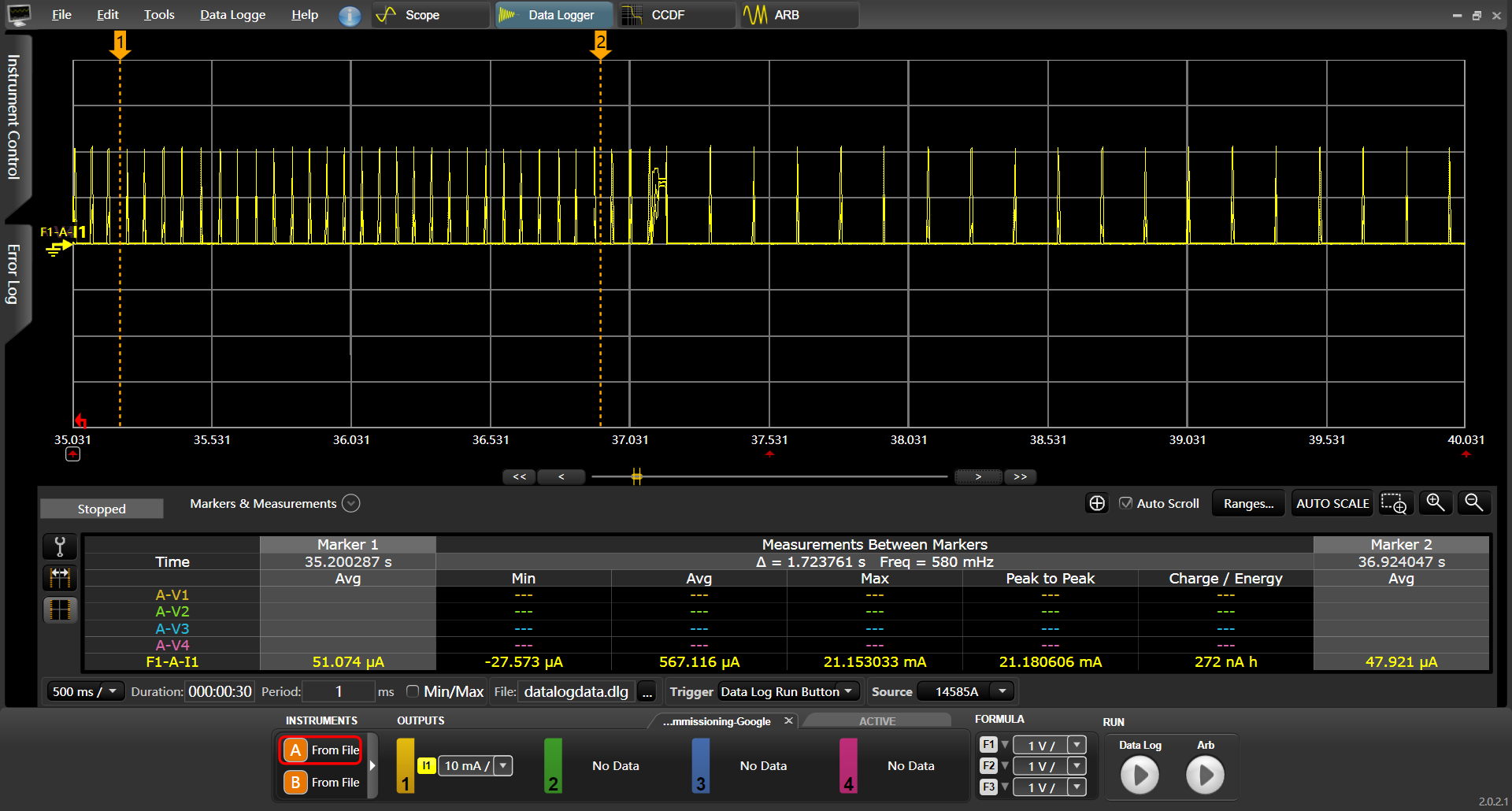
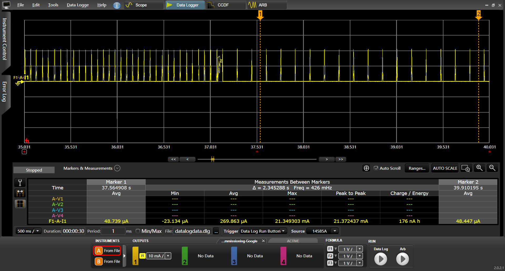
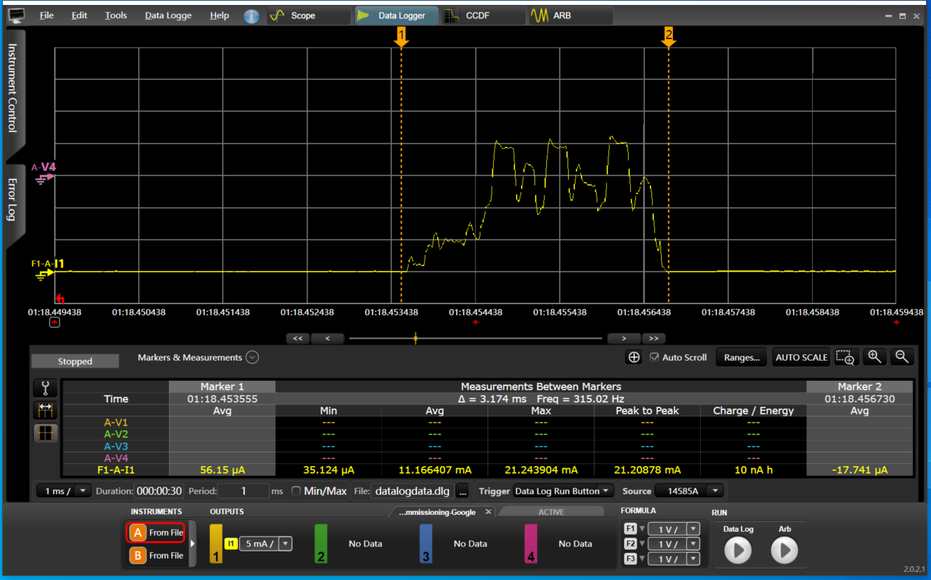
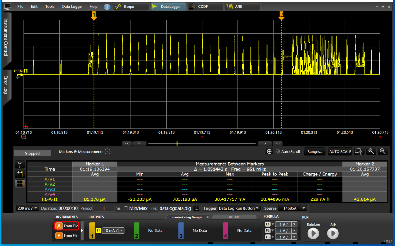
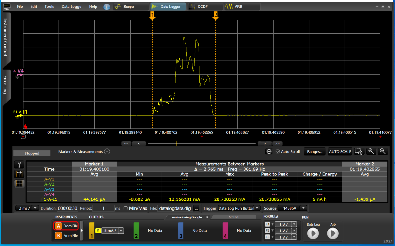
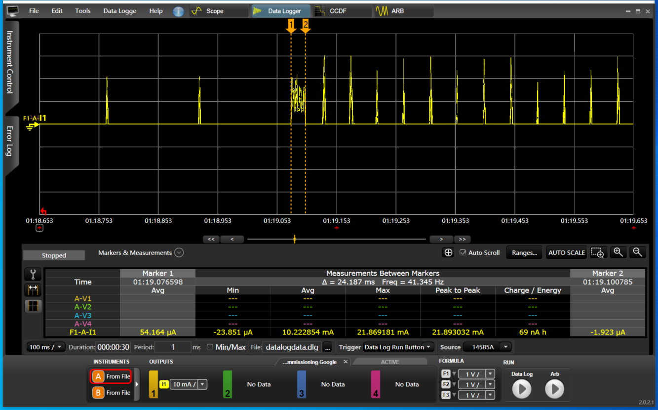
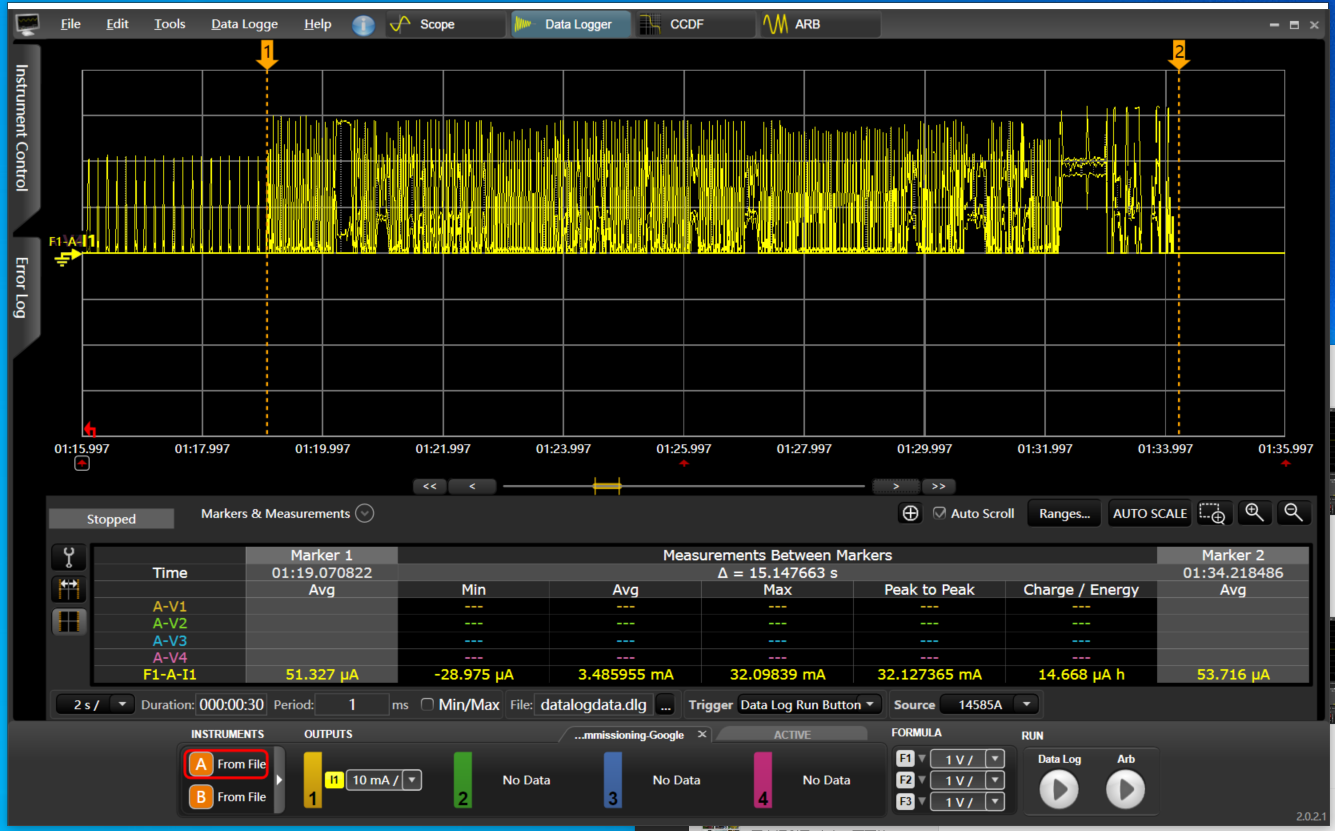
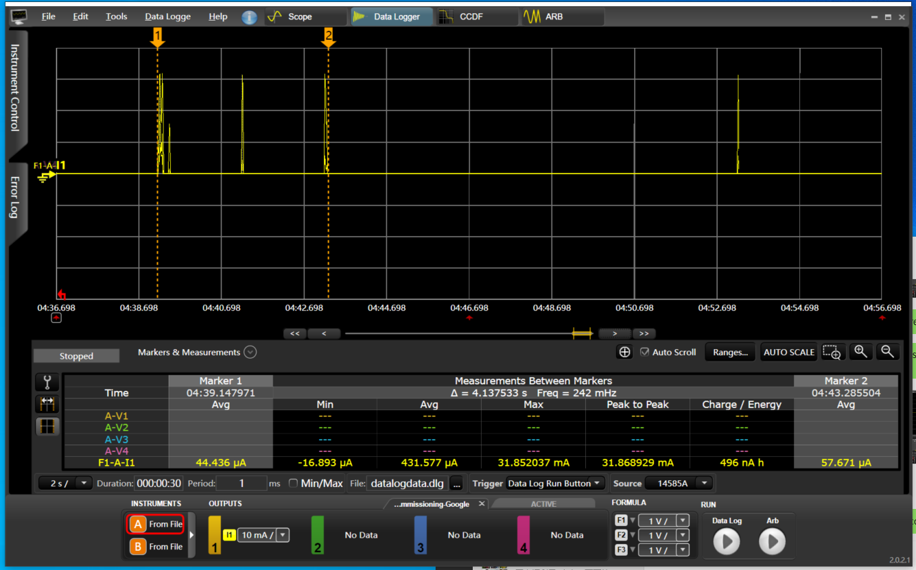
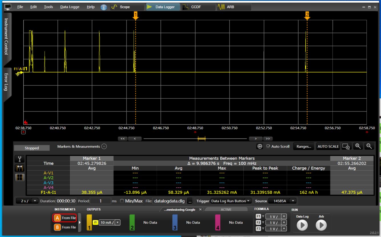
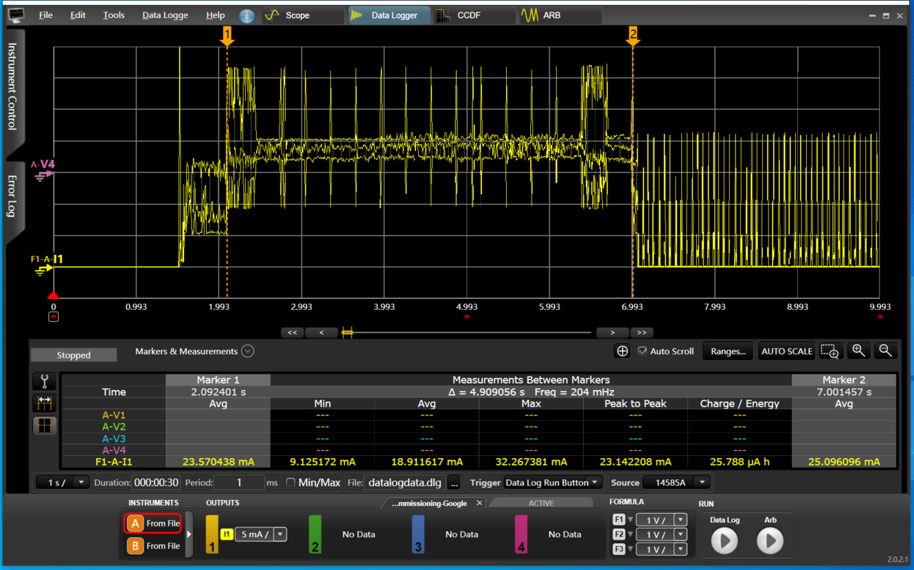
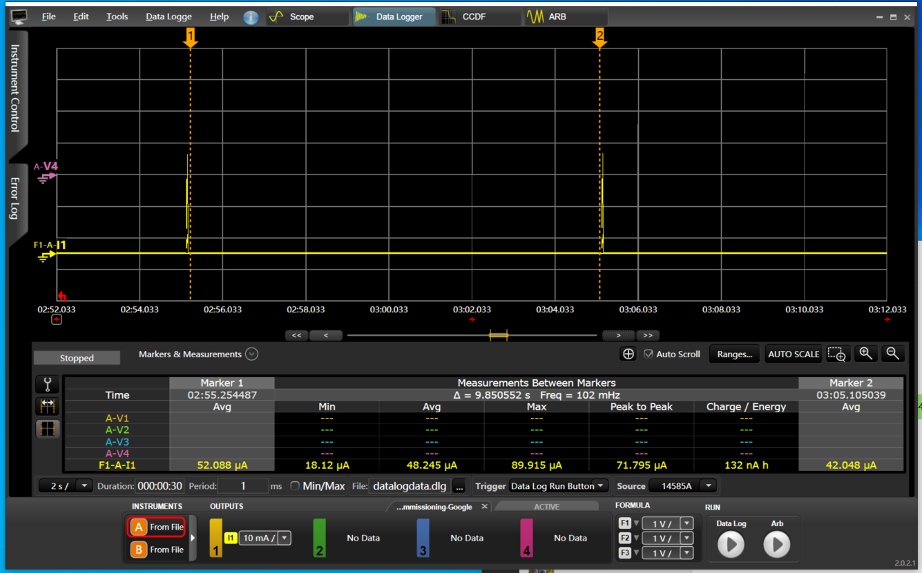
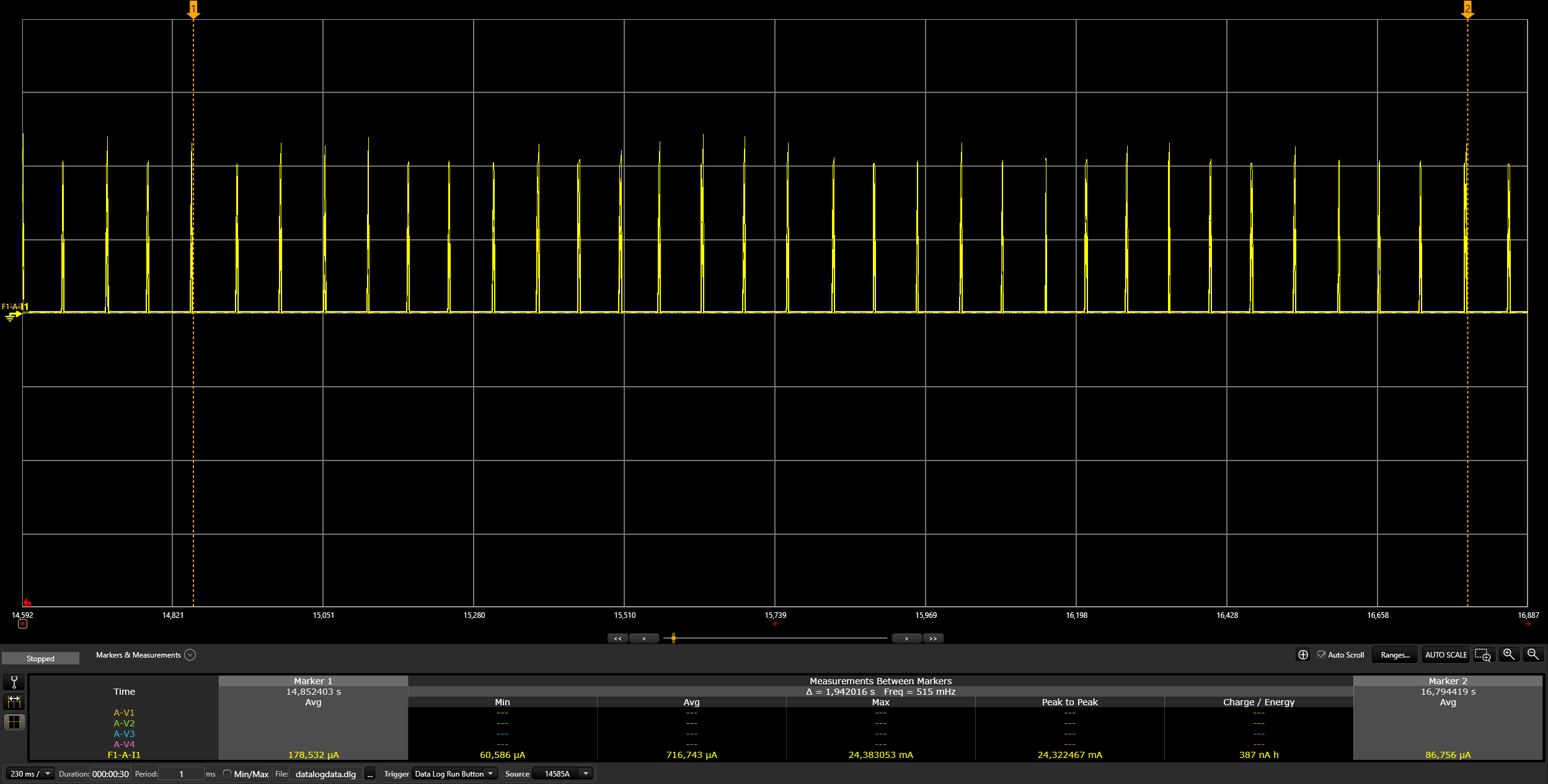
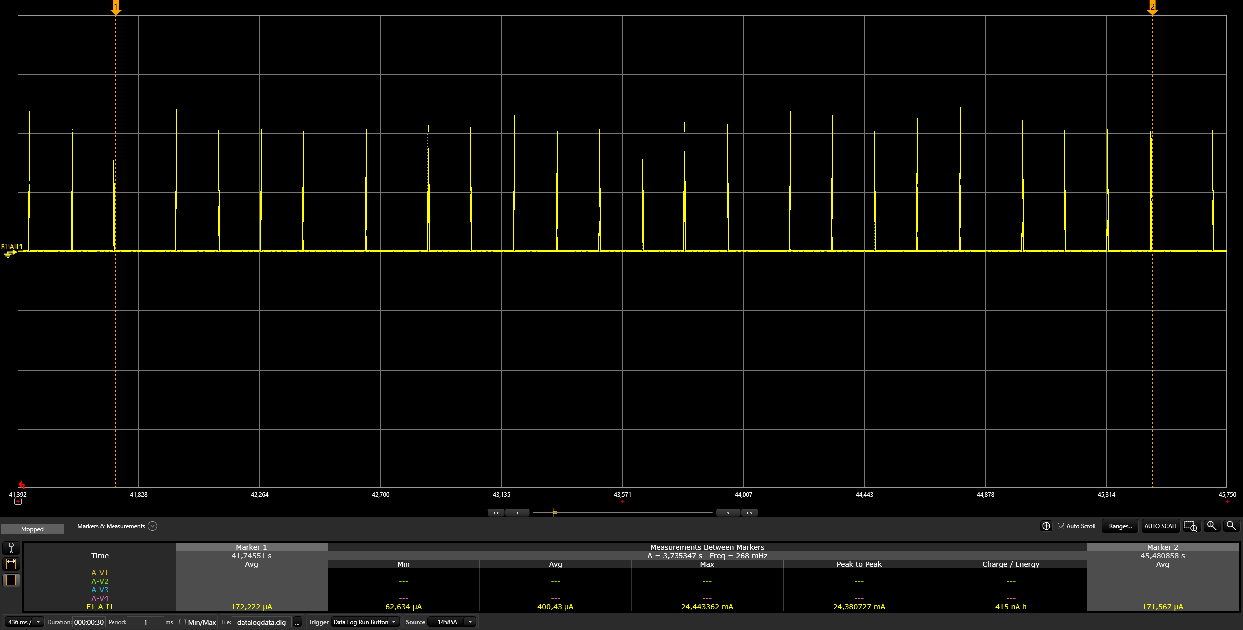
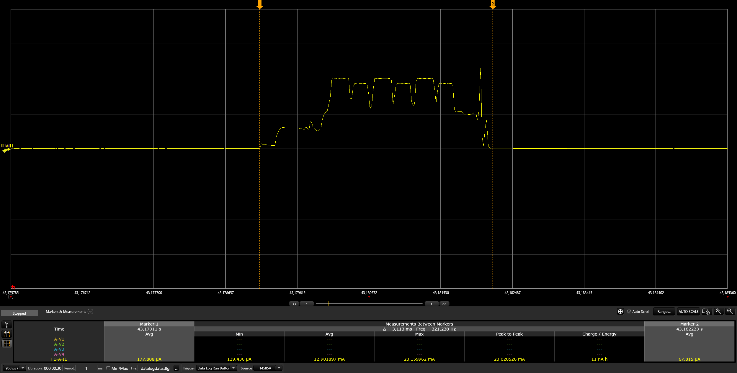
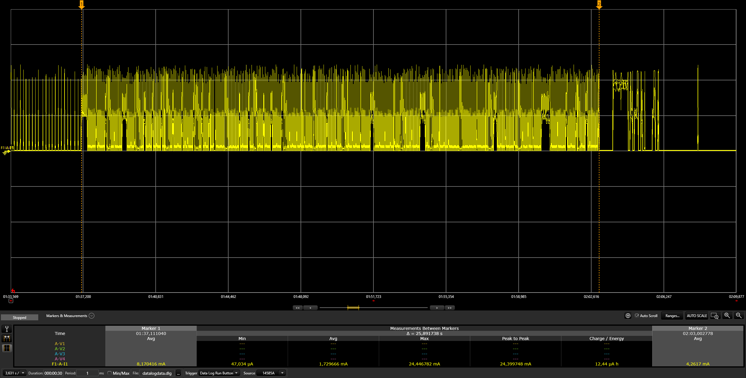
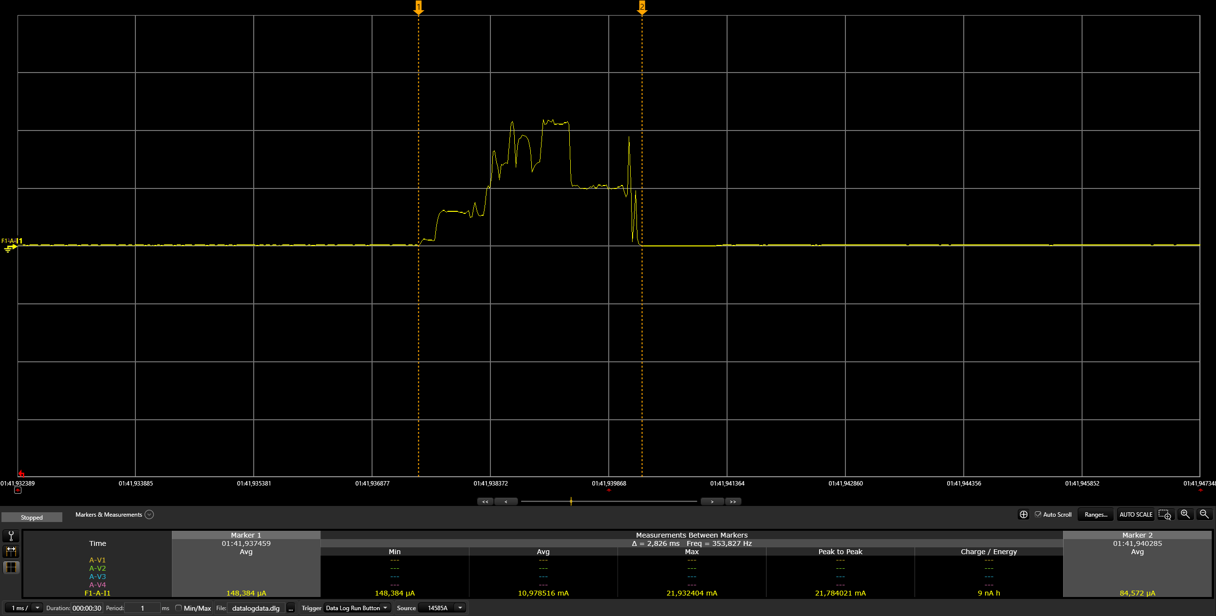
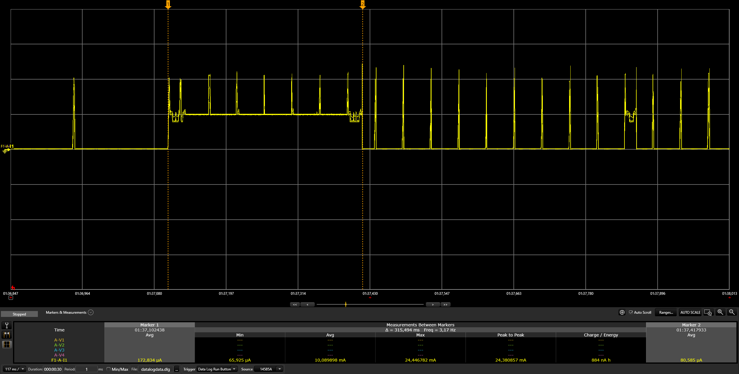
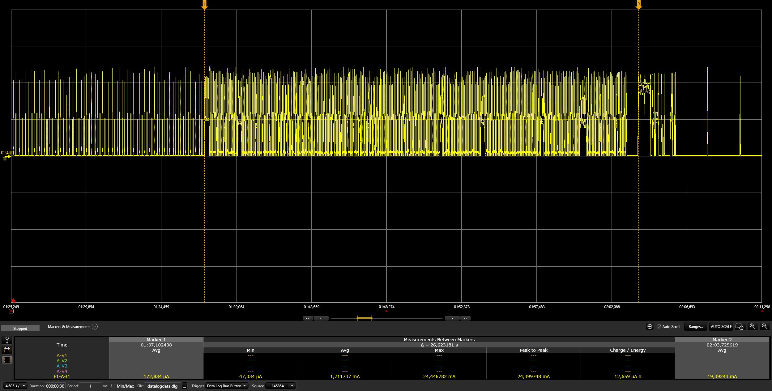
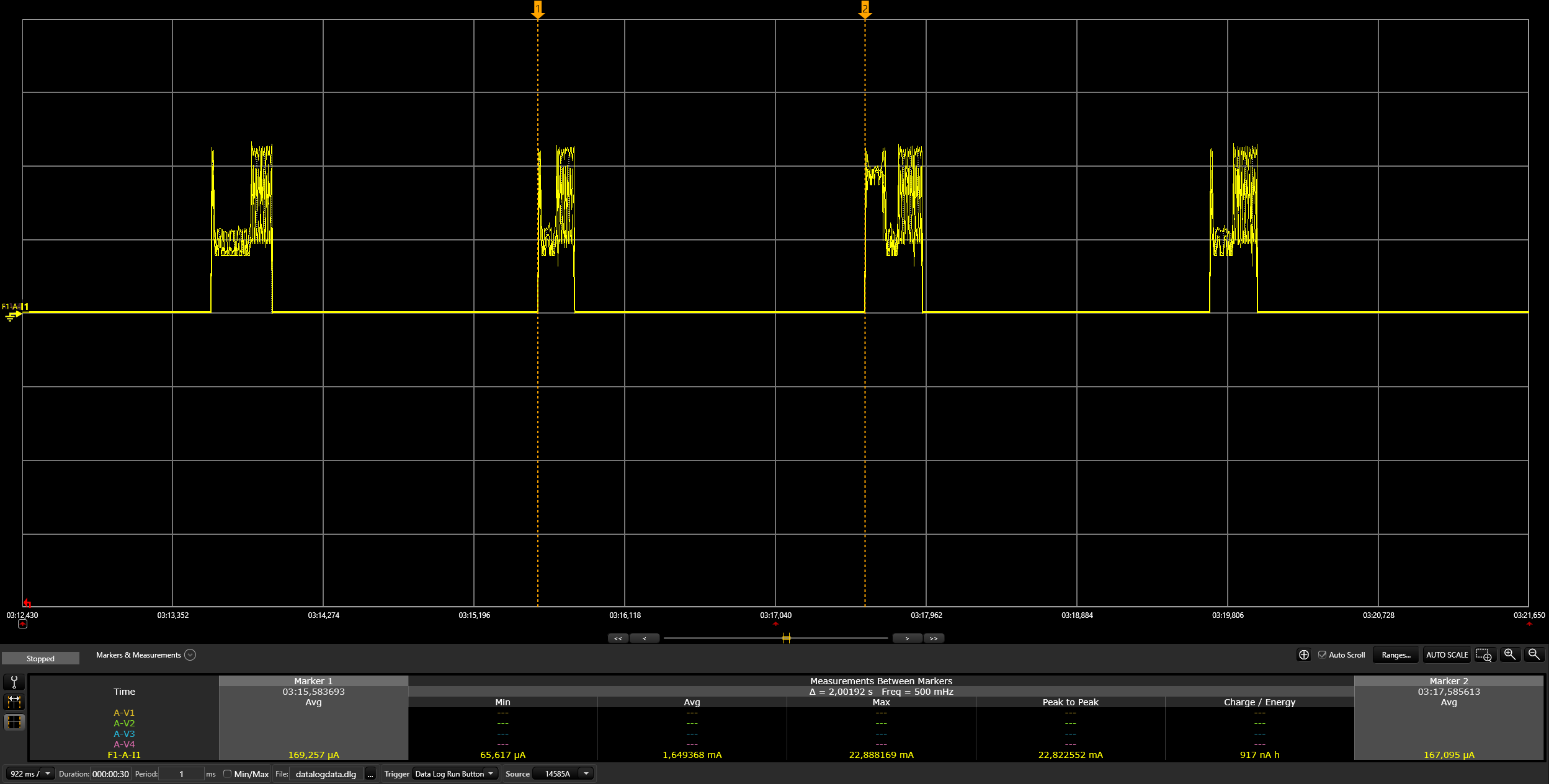
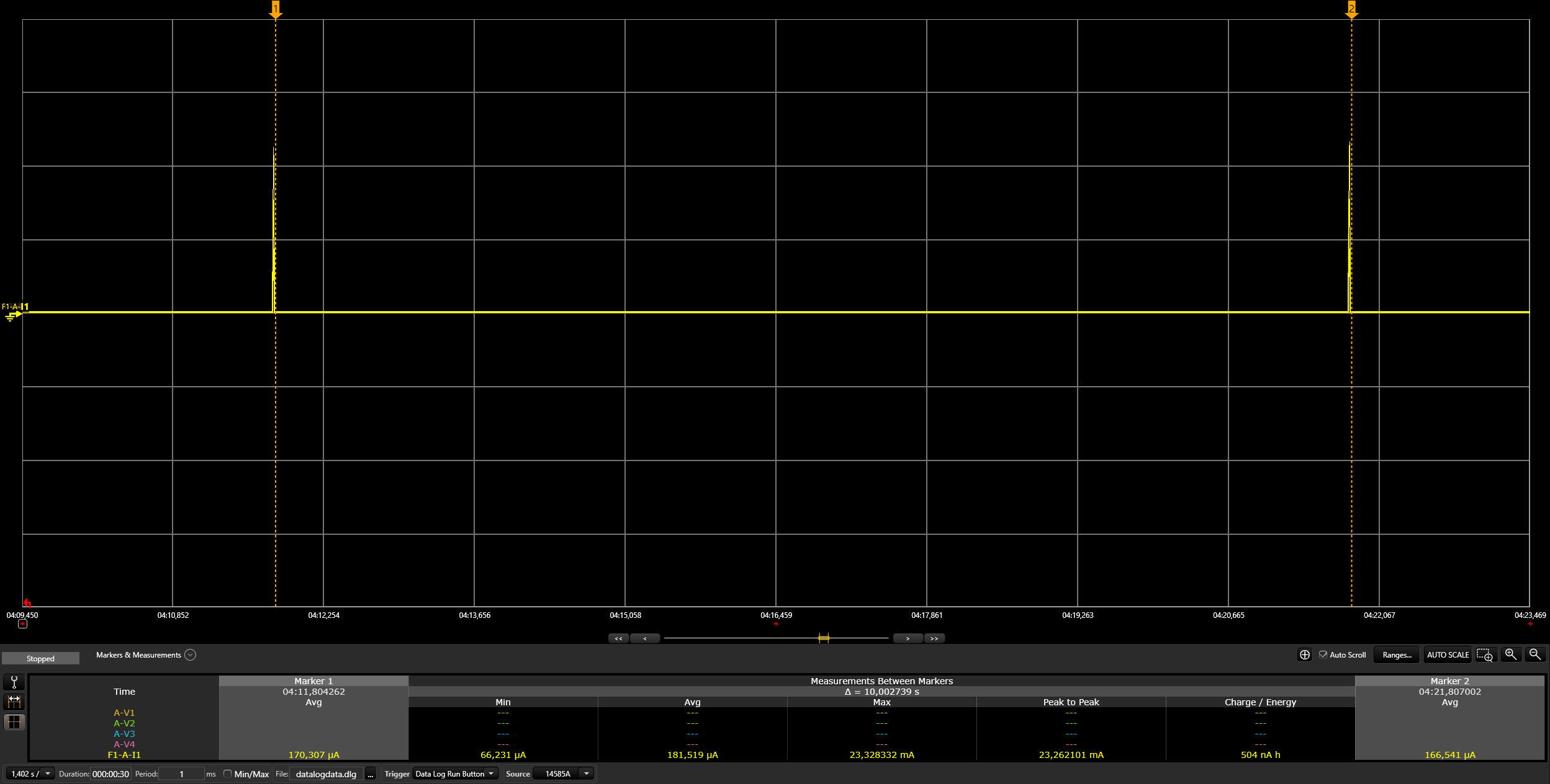
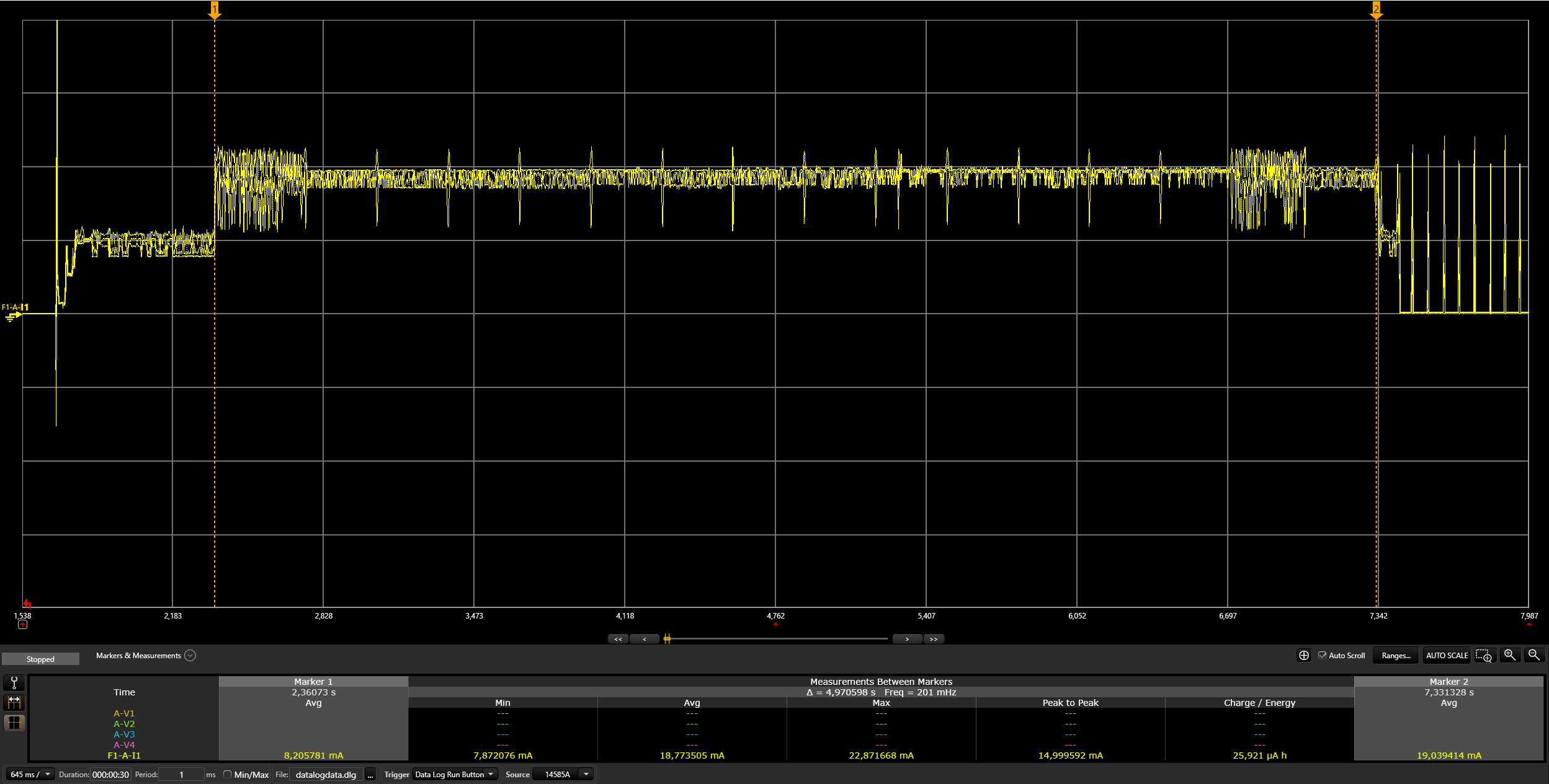
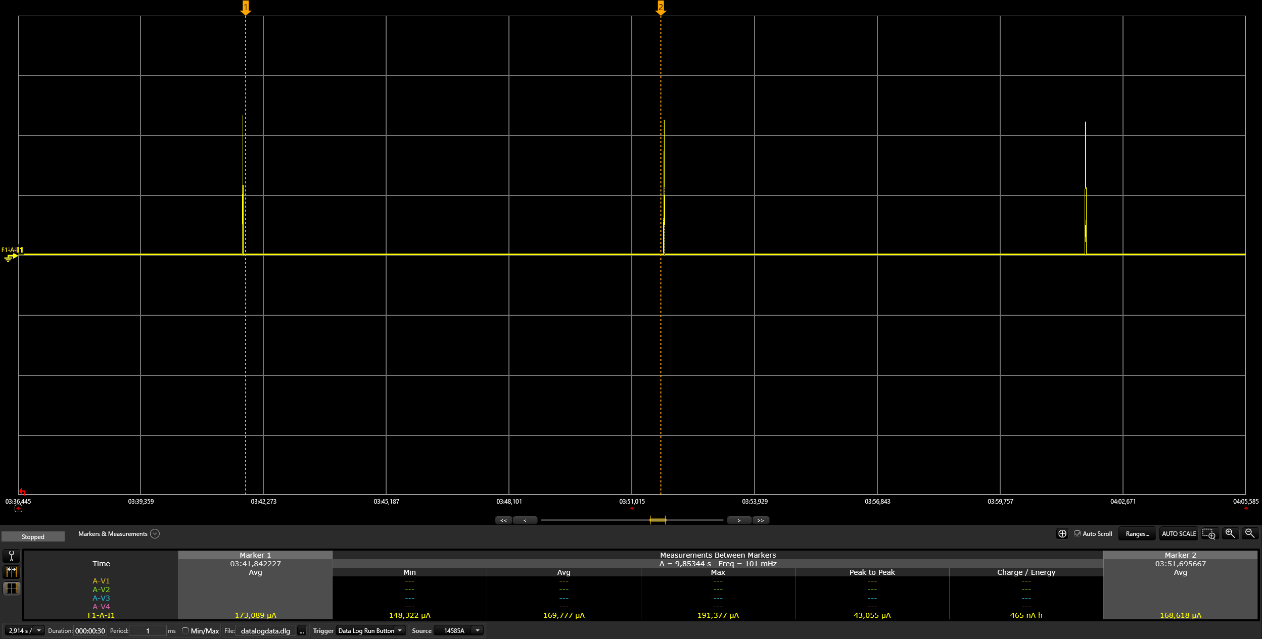
Will be provided later.
Enable NFC Functionality:
CONFIG_CHIP_NFC_COMMISSIONING to y (yes) or n (no). For enabling NFC functionality, it should be set to y.Optional Tuning:
NFC Board Replacement:
If alternative NFC boards with compatible drivers are available, they can be used.
Configuration Adjustments:
Modify the following in KConfig (located at connectedhomeip/config/telink/chip-module/):
For a different NFC board's connection type, change the setting in CHIP_NFC_COMMISSIONING to imply I2C.
For a different NFC board model, adjust CHIP_NFC_COMMISSIONING to imply ST25DVXXKC, based on the Zephyr drivers.
Note: The current branch of the Zephyr project does not support NFC devices. Utilize the specific Zephyr branch at this GitHub link for NFC functionality.
Currently, the Zephyr drivers support only the ST25DVXXKC NFC device. To connect it to the Telink EVK board, use the following pin configurations:
TLSR9218adk80d EVK Pin Configuration:
| Name | Pin |
|---|---|
| SCL | PE1 (pin 6 of J34) |
| SDA | PE3 (pin 7 of J34) |
| GND | GND (pin 23 of J51) |
| +3.3V | TL_VBAT (pin 15 of J51, without removing jumper) |
TLSR9528A EVK Pin Configuration:
| Name | Pin |
|---|---|
| SCL | PC0 (pin 11 of J3) |
| SDA | PC1 (pin 13 of J3) |
| GND | GND (pin 7 of J17) |
| +3.3V | TL_VBAT (pin 3 of J17, without removing jumper) |
Note: For I2C devices, ensure the presence of pull-up resistors. If absent, add external 5kΩ resistors on the SCL and SDA lines.
Simply tap your smartphone on the NFC tag and select an app (e.g., Google Home) to begin the commissioning process.
Choose an NFC board with I2C, SPI, or another interface supported by Telink EVK boards.
Incorporate the new NFC driver into the Zephyr project:
(zephyr/drivers/nfc/, zephyr/include/drivers/nfc/).
Add the NFC device to Telink DTS (boards/riscv/tlsr9518adk80d/tlsr9518adk80d-common.dtsi) and
(boards/riscv/tlsr9518adk80d/tlsr9528a-common.dtsi).
Change the NFC device in the Matter project's KConfig
(connectedhomeip/config/telink/chip-module/):
For your new NFC board's connection type, adjust the setting in CHIP_NFC_COMMISSIONING to imply I2C.
For your new NFC board's model, set CHIP_NFC_COMMISSIONING to imply ST25DVXXKC, following the Zephyr drivers.
Published by
Telink Semiconductor
Bldg 3, 1500 Zuchongzhi Rd,
Zhangjiang Hi-Tech Park, Shanghai, China
© Telink Semiconductor
All Right Reserved
This document is provided as-is. Telink Semiconductor reserves the right to make improvements without further notice to this document or any products herein. This document may contain technical inaccuracies or typographical errors. Telink Semiconductor disclaims any and all liability for any errors, inaccuracies or incompleteness contained herein.
Copyright © 2023 Telink Semiconductor (Shanghai) Co., Ltd.
For further information on the technology, product and business term, please contact Telink Semiconductor Company www.telink-semi.com
For sales or technical support, please send email to the address of:
telinkcnsupport@telink-semi.com
Version Change Description
V0.1.0 Preliminary release
V0.2.0 Added section about docker image
V0.2.1 Removed temporary step for Matter project setup
V0.2.2 Added Light-Switch-App
V0.2.3 Fixed markdown lint warnings
V0.2.4 Updated Raspberry Pi image
V0.2.5 Updated docker image
V0.2.6 Updated minimum Ubuntu version to 20.04 LTS
V0.2.7 Updated repos url and added Form Thread network via CLI
V0.2.8 Added OTA section
V0.2.9 Added factory data section
V0.2.10 Added thermostat app and modified URL in factory data section
V0.2.11 Added Flash Layout information
V0.2.12 Update factory data Section
V0.2.13 Update .dts modification
V0.2.14 Update Zephyr branch
V0.2.15 Update power management relative project configs
V0.2.16 Update Zephyr SDK version
V0.2.17 Update docker image repo
V0.2.18 Added bootloader configuration information
V0.2.19 Add power on Factory reset
V0.2.20 Added extended power management information
V0.2.21 Update flash partitions and latest master adaptations
V0.2.22 Added certification info
V0.2.23 Updated RF power and Matter ICD mode data
V0.2.24 Updated bootstrap script usage
V0.2.25 Updated Device Configuration section with openthread configuration
V0.2.26 Add NFC tag support
V0.2.27 Added TLSR9528A deep sleep measurement data


邮箱
邮箱
The new password
Confirm password