B92 Channel Sounding User Guide
Introduction
There is one UART serial device in Channel Sounding (CS) development kit, which is for ACL connection establishment and CS establishment between PC and CS_central.
In CS development kit, user can modify configuration by UART.
For example, if users use cs_acl_central to scan advertisements, and report these advertisements, user can send "scan start" to trigger scan event by UART.
If the user doesn't know the argument list of some command, user can send command to achieve them, and they will be sent to PC. For example, if user doesn’t know the argument list of command "scan", user can send "scan", and the device will reply with "scan \
In CS development kit, use PA2 as UART Tx pin and PA3 as UART Rx pin by default.
Operation Demonstration
Hardware and Software Requirement
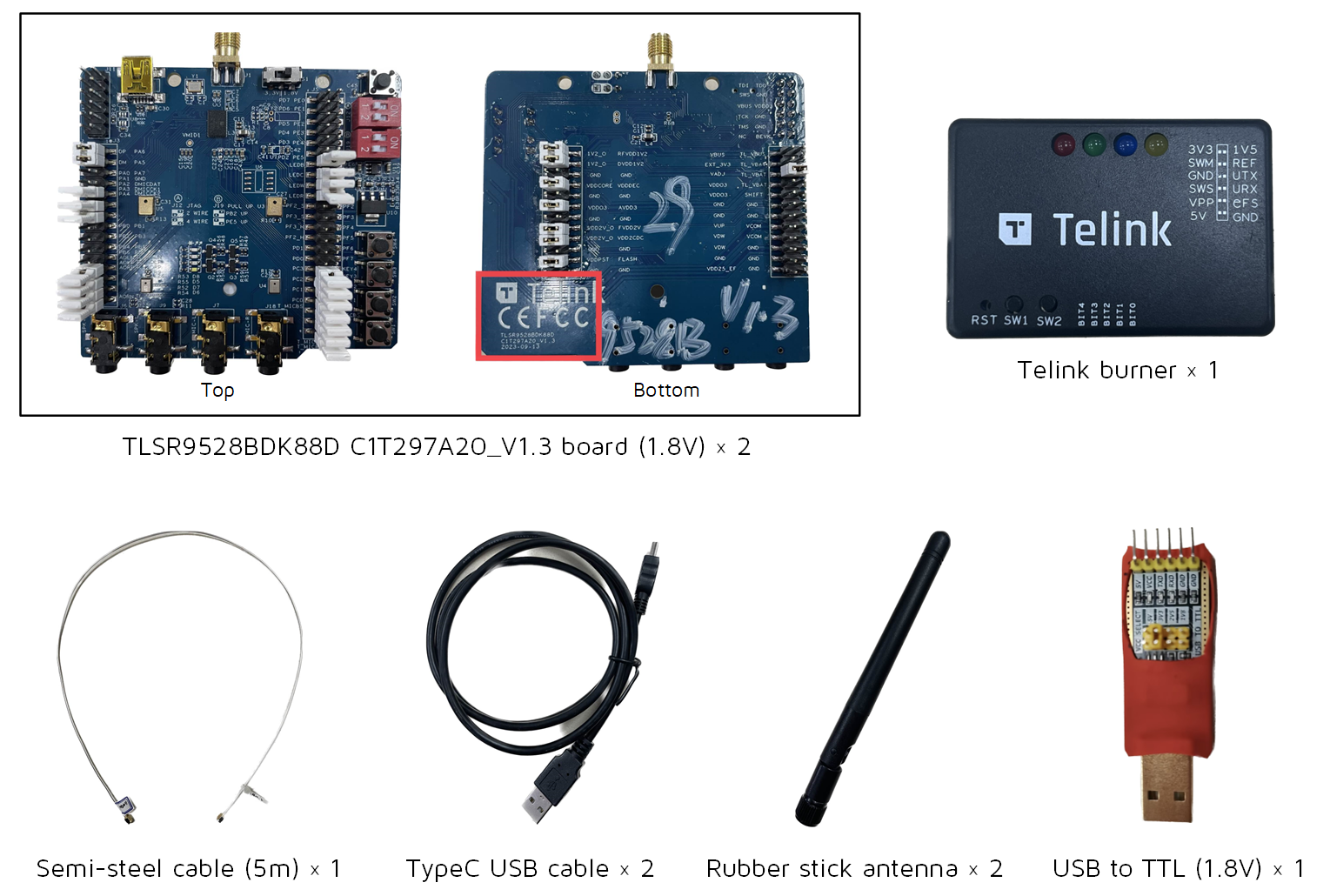
Telink Channel Sounding Development Kit
Software Requirement
-
Burning Tool (Telink BDT)

-
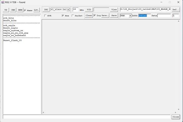
RISC-V TDB

-
Serial terminal
-
SDK
Test
Test Instructions
- The channel sounding development kit has two roles: cs_acl_central (CS role is initiator by default) and cs_acl_peripheral (CS role is reflector by default).
- The test has two modes of signal transmission: semi-steel cable and rubber stick antenna.
Test Procedure (using semi-steel cable as an example)
Step 1 Burning Firmware
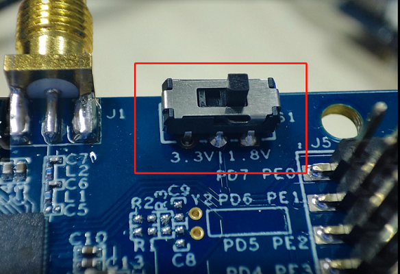
(1) Select 1.8V on the development board.
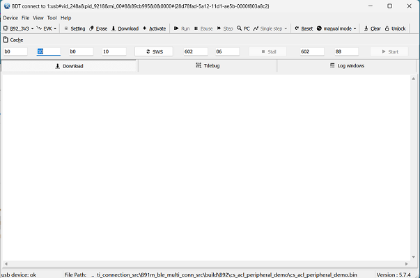
(2) Use the BDT to burn the development boards separately.
The burned file is:
cs_acl_central_xxx.bin: build from the cs_acl_central project.
cs_acl_peripheral_xxx.bin: build from the cs_acl_peripheral project.
The two ends of the Telink burner are connected to the PC and development board respectively, and the bin file is burned from BDT to the development board through Telink burner.
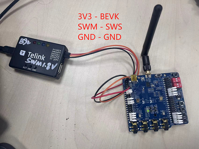
The picture above is for reference only, the actual product may have updated appearance.
Note:
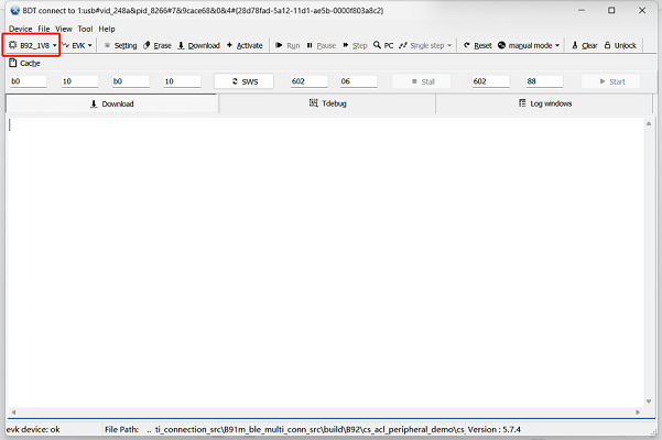
Select B92_1V8 mode in BDT.
(3) The cs_acl_central_xxx.bin is burned into the initiator device and cs_acl_peripheral_xxx.bin is burned into the reflector device. After burning, the blue light will flash on the initiator device, and the green light will flash on the reflector device.
(4) To prevent the current from returning, after burning, users need to unplug the Telink burner's cable that is connected to the device, and then use USB to power the device.
Step 2 Environment Setup
After burning, start setting up the test environment:
-
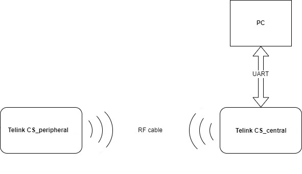
Connect the two devices via semi-steel cable (replace the semi-steel cable with rubber stick antenna for RF wireless testing).
-
One end of the "USB TO TTL" converter (with rubber protective sleeve) is connected to the UART pins (UART1_RX_PA3, UART1_TX_PA2, GND) of the initiator device and the other end is connected to the PC.
-
The initiator device is connected to the PC via a USB cable, the RISC-V TDB software on the PC will prompt: "Found" and can be log printed, the reflector device can be powered by 5V USB.
As shown in the figure below to set up the test environment.
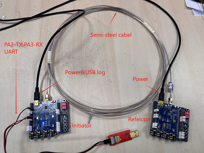
The picture above is for reference only, the actual product may have updated appearance.
Step 3 Execute Command
After burning, use the serial tool to print the results using the following commands:
(For details of the command, please refer to chapter 3 UART Command)
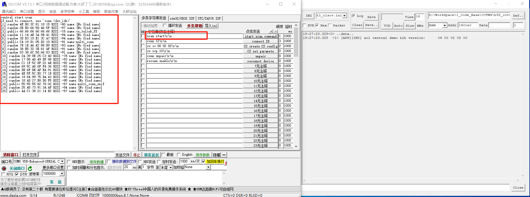
scan start\r\n           //step1: Start scanning advertising
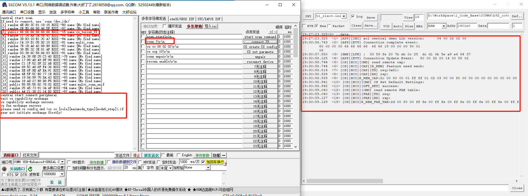
conn 3\r\n               //step2: Connect device 3: "3" is the mac address index of the desired connected device.
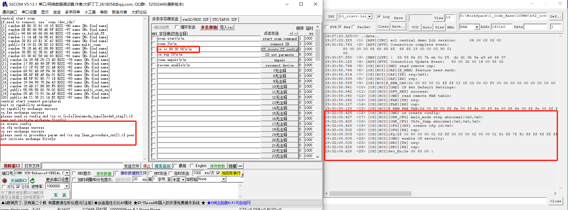
cs cc 00 02 02\r\n       //step3: Create CS configuration to select mainmode and the number of mode0:
                         //"00" means CS initiator role
                         //The first "02" means mainmode2, it can be changed to 01 that means mainmode1
                         //The second "02" means the number of mode0, the range of this option is 01/02/03.
cs scp 10\r\n            //step4: Number of tests: "10" means test ten times, which can be modified to the number of tests required.
reconn enable\r\n        //Step 1 and 2 can be skipped during reconnection, without advertising and connecting again, using the "reconn" command.
During the execution of the above command, the LED status will change with Bluetooth connection and disconnection, the user can judge the LED status by the following table:
| Device | Chip_Reset | Bluetooth connection | Bluetooth disconnection |
|---|---|---|---|
| Initiator | Blue light flashing | Blue light flashing + Red light always on | Blue light flashing + White light always on |
| Reflector | Green light flashing | Green light flashing + Red light always on | Green light flashing |
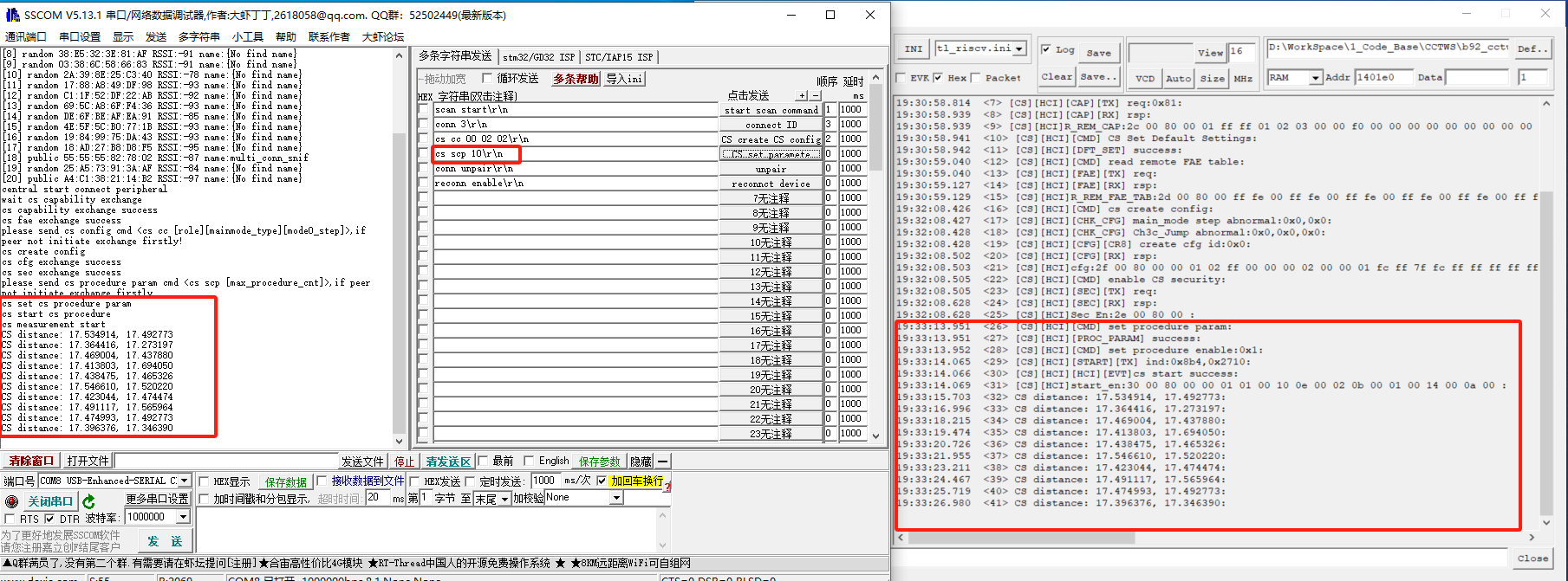
The figure corresponding to each line of code above is as follows, with the serial commands on the left and the corresponding log on the right.
scan start\r\n
conn 3\r\n
cs cc 00 02 02\r\n
cs scp 10\r\n
reconn enable\r\n
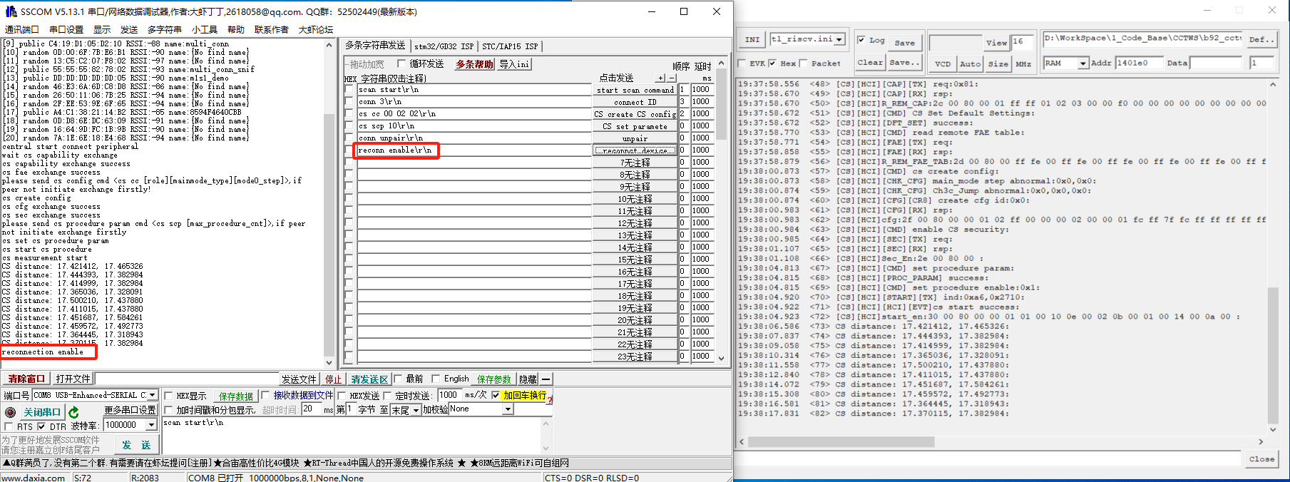
Log description:
Each log has two values.
-
For Mainmode1: Both values are test results and the values are the same.
-
For Mainmode2: The first value is phase-distance, and the second value is music-distance (they are the results of two different algorithms).
Test Results
Test conditions: 1.8V power supply.
Note:
For more accurate test results, please use semi-steel cable directly, or test in an open environment. Testing in the office and other electromagnetic environment complex place will lead to large test error. We will improve the distance measuring algorithm in the future.
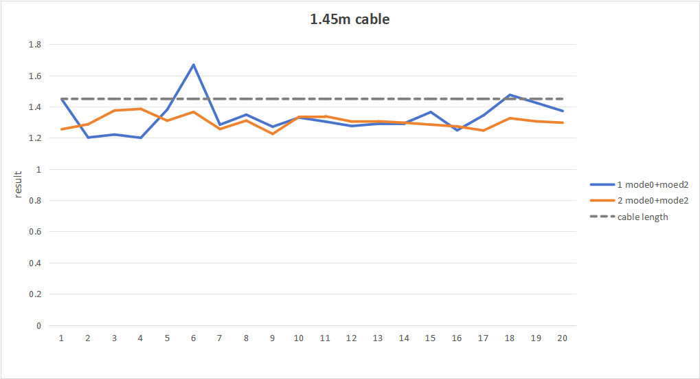
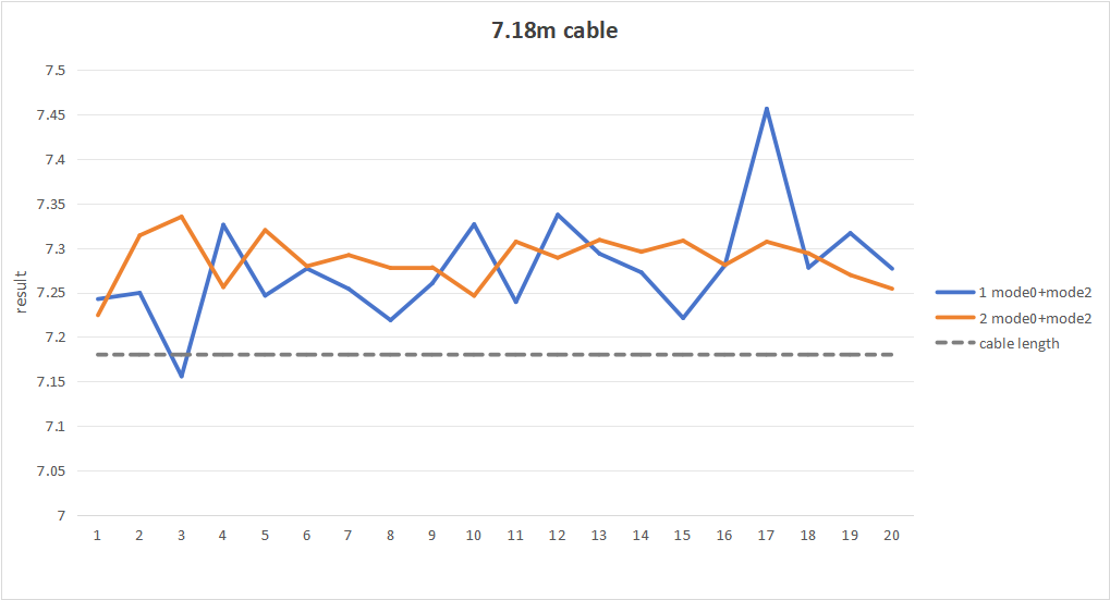
Pass verdict: According to the "Bluetooth Core Specification", the test error within 0.5m meets the expectation when the actual distance is less than 5m, and the error within 10% meets the expectation when the test distance is more than 5m.
Note:
The test result is the electrical length, and the number marked on the semi-steel cable is also the electrical length.
Below is a more visual and detailed waveform of the test results:
Test conditions: mode2, 1.45m cable. (The length here refers to the electrical length, not the physical length)
Test conditions: mode2, 7.18m cable. (The length here refers to the electrical length, not the physical length)
UART Command
All UART string commands sent from the PC need to add '\r' '\n' at the string end. Such as "scan start" command, user need to input "scan start\r\n".
The UART interface is used, PA2 as UART Tx pin and PA3 as UART Rx pin by default in b92 EVK board.
Scan Advertisement in Central Role
The command format for scanning advertisements: scan \
Scan Start
Enable the scan, the central will first reply with "central start scan\r\n". If need to connect, use "conn \
Then if the advertising device is scanned, it will be reported in the following format.
[dev_idx] <public/random> xx:xx:xx:xx:xx:xx RSSI: xx name: complete name
The following is an example of the scan.
[1] public 12:34:56:00:00:00 RSSI: -60 name:Telink-ADV
Where dev_idx needs to be filled in when connecting afterwards.
The maximum of dev_idx is MAX_ADV_INFO_NUM. MAX_ADV_INFO_NUM is a macro that it is 20 by default.
Scan Stop
Stopping the scan, the central will first reply with "central stop scan".
Scan Clear
Clearing the advertisement information that has been scanned, the central will first reply with "central clear adv info".
Scan Filter
Filter scan result with expected MAC address. cmd format is "scan filter \
One can start scan filter with "scan filter \
The "scan filter disable\r\n" and "scan filter enable\r\n" are used after setting filter MAC address. After disable, user can see 20 scan results again.
Initiate Connection in Central Role
The command format for connecting specific advertisement devices: conn \
where dev_idx is the index value reported after the command "scan start". For example, if need to connect device that its dev_idx is 1, user can use the following command:
conn 1
If the index value does not exist, the device will reply:
connect index error
If the index value exists, the central will create an ACL connection with the corresponding advertising device. And reply with "central start connect peripheral".
Toggle Reconnection in Central Role
The command format to toggle re-connection: reconn \
Reconn Enable
Enable the re-connection, the central will first reply with "reconnection enable\r\n". If scanning is stopped, scanning will be started. When scan advertisement which transmitted by bonded device, the central will auto reconnect to this device.
Reconn Disable
Disable the re-connection, the central will first reply with "reconnection disable\r\n". When scan advertisement which transmitted by bonded device, the central will not auto-reconnect to this device.
Delete Pairing Info
User can use this command ("conn unpair\r\n") to disconnection and clear all bonded information stored in the local flash. After, User need to scan enable and establish new connection.
Channel Sounding Command
The command format for channel sounding procedures. Before a CS measurement, central and peripheral device need interact mainly with the following procedures: CS Capabilities Exchange Procedure, CS Mode0-FAE Table Request Procedure, CS Configuration Procedure, CS Security Start Procedure, CS Start Procedure.
When the ACL connection is established, CS Capabilities Exchange Procedure, CS Mode0-FAE Table Request Procedure and CS Security Start Procedure will automatically exchange. User needs to send UART command to exchange CS Configuration Procedure and CS Start Procedure. When all these procedures have exchanged completely, the CS measurement will be started automatically.
Channel Sounding UART commands: "cs rst", "cs cc xx xx xx", "cs scp", "cs log". The parameters of these commands are temporary and may be added or deleted in the future.
CS Reset Command
CS reset command is abbreviated as "cs rst". User can use this command to reset CS all parameters and status.
CS Create Config Command
CS create config command is abbreviated as "cs cc \
\
\
\
CS Start Command
CS start command is abbreviated as "cs scp \
Sniffer of Ellisys
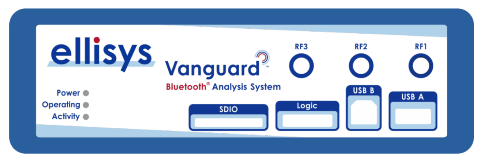
Analyzer Hardware Information
ACL Link Decryption
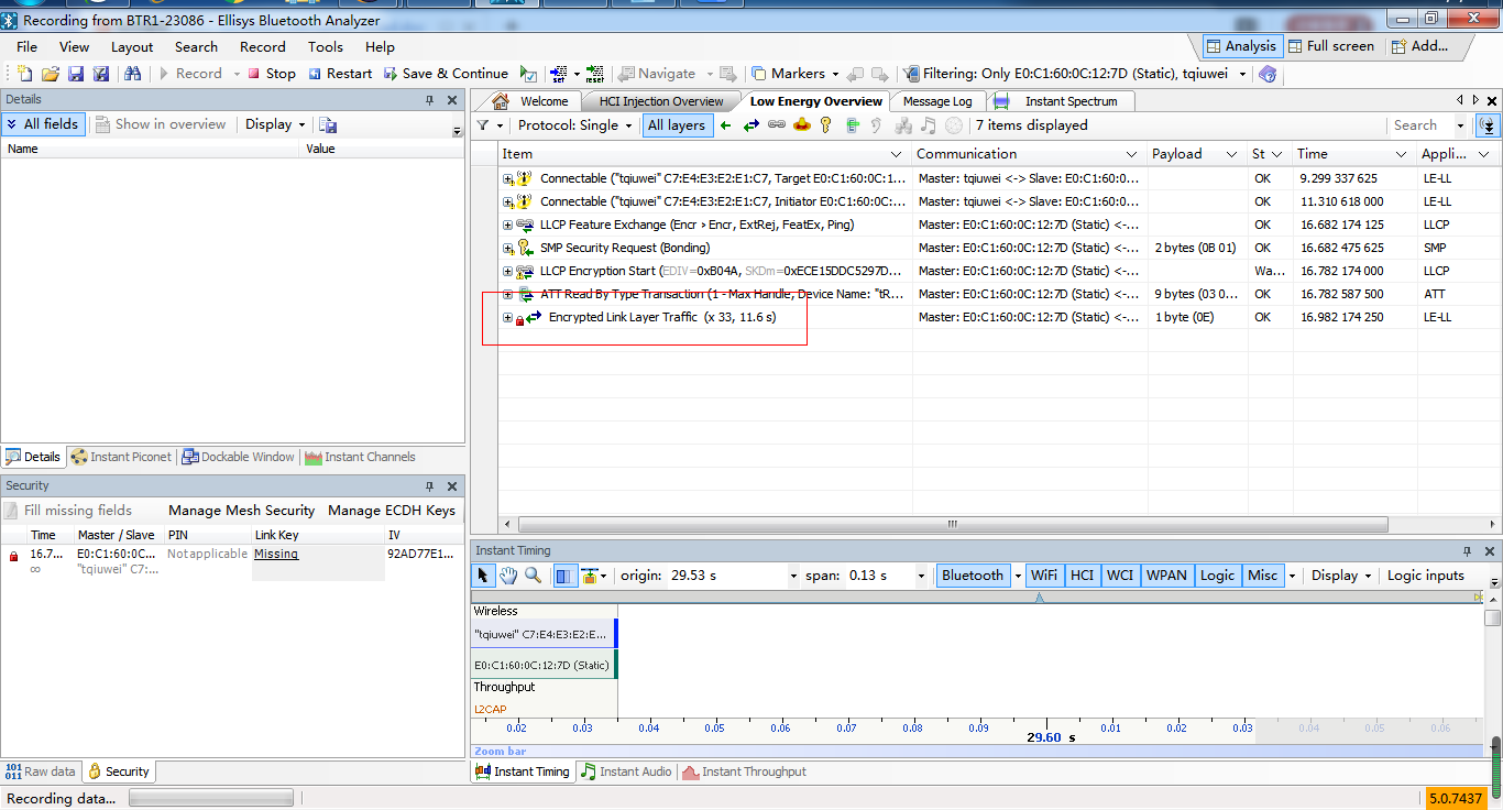
When we use Ellisys to capture packets, decryption failure may happen.
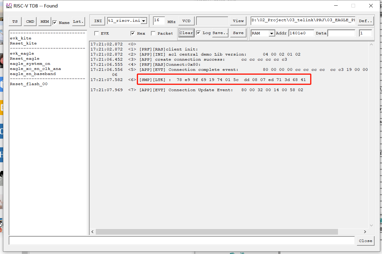
A method to solve this problem: from our equipment for LTK on the log, and then added LTK to the Ellisys, Ellisys can decrypt the packets successfully.
The following are the procedures:
(1) When decryption fails, the user can see the following information:
(2) Read the LTK from the log or the flash. For example, the CS development kit log will automatically display the LTK after the first pairing or link back, as follows:
(3) Copy the LTK into Ellisys. Find Ellisys interface as follows: Security | Link Key.
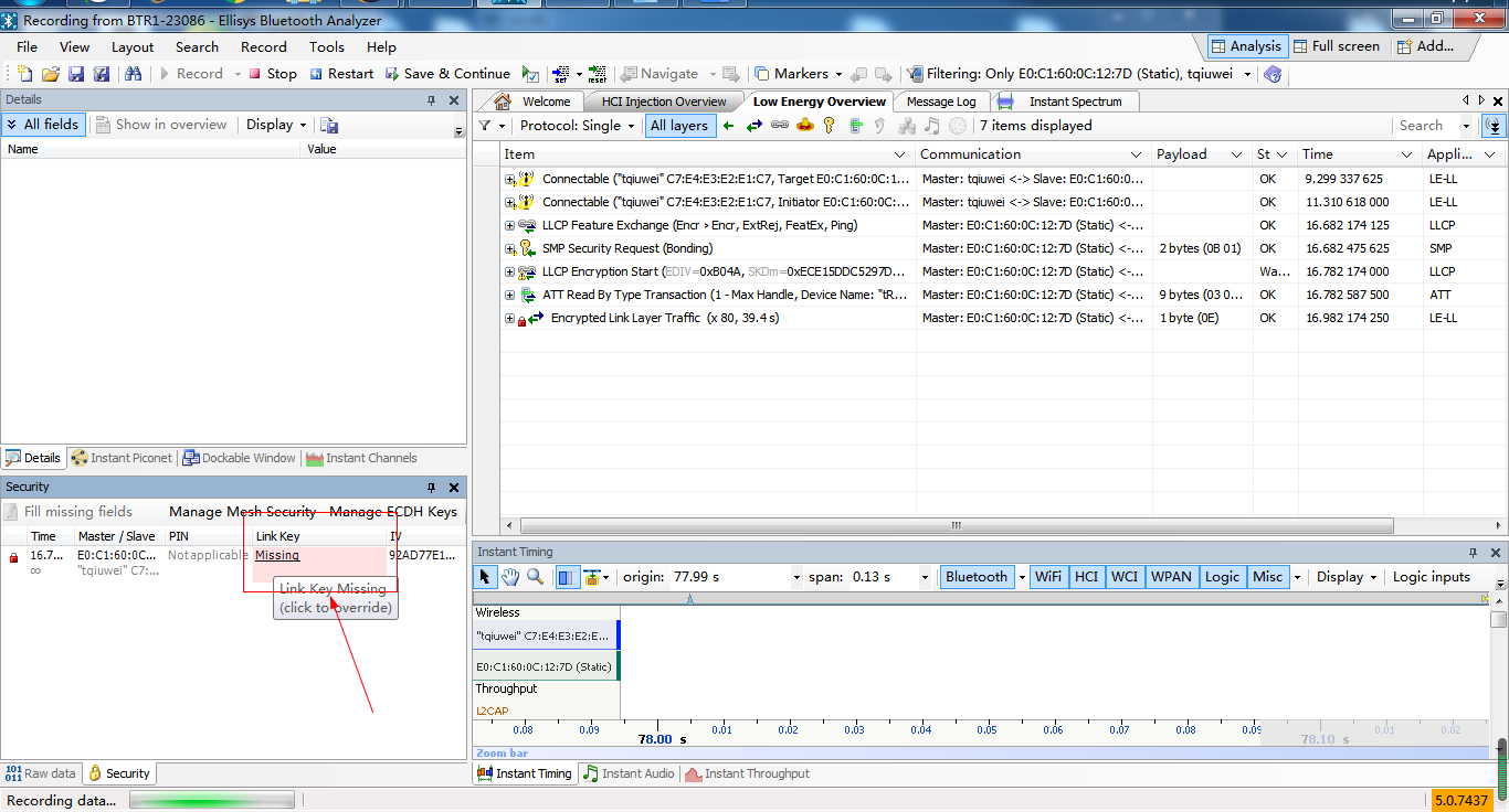
Then double-click the Missing, it appears the following interface:
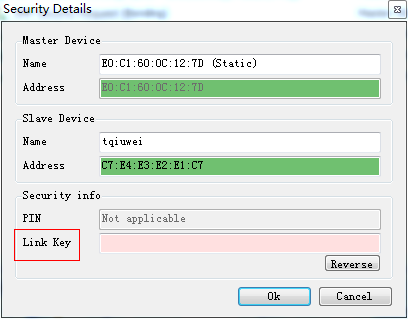
Then paste LTK into the "Link Key" box (try clicking Reverse if you get an error) and click OK.
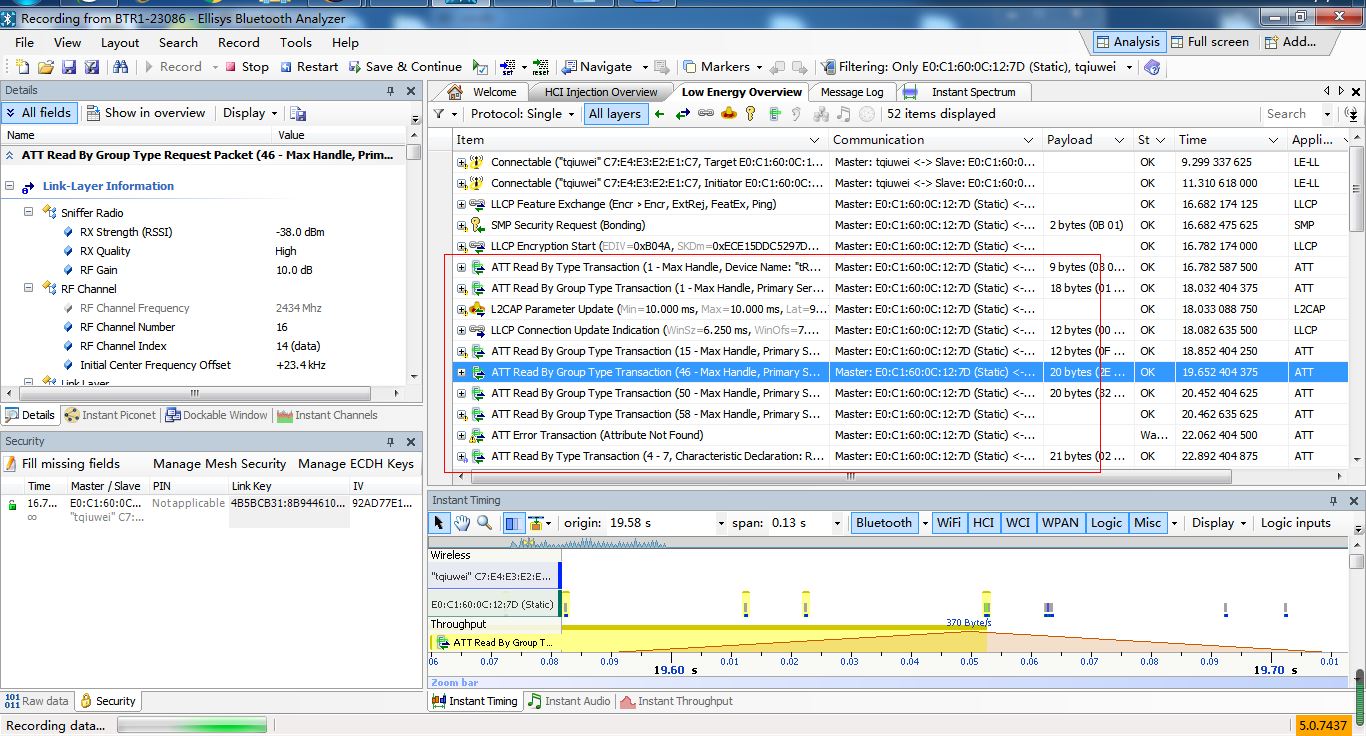
All the data can be decrypted and seen as shown below:
