BT/BLE Dual-mode SDK
Overview
The BT/BLE dual-mode SDK applies to Telink TLSR951x series chip. It is a set of general dual-mode Bluetooth solutions based on Bluetooth 5.0, which supports three BT Classic links (two ACL and one SCO) and one BLE (slave) link. The SDK supports Bluetooth audio and Bluetooth voice functions, provides convenient related development methods and has good readability, extensibility and portability. The SDK is modular oriented, providing rich interfaces, clear hierarchy and logic between modules, simple and easy to understand, providing a good basis for users to learn and develop. The overall design goal of the SDK is to allow users to form high-quality products in a shorter period of time through configuration or secondary development of the SDK.
Function Overview
Currently, the dual-mode SDK supports the following functions:
- Supports two BT ACL connections, one master and one slave (one headphone, one mobile phone)
- Supports one BT SCO connection
- Supports one BLE ACL connection
- Supports A2DP Sink and Source
- Supports HFP HF and AG
- Supports PBAP-Client
- Supports SPP transfer
- Supports File System
- Supports battery detection and low voltage protection
- Supports system monitoring (stack detection, watchdog)
- Supports USB devices (Audio, HID, CDC, MSC)
- Supports MP3 decoding
- Supports MSBC codec
- Supports CVSD codec
- Supports Bluetooth modular management and application management
- Supports audio modular management and application management
- Supports voice noise reduction
- Supports echo cancellation
Code Structure
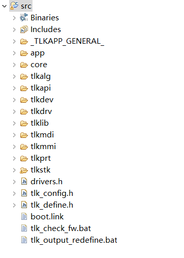
- _TLKAPP_GENERAL_: Compile the output file, the burned bin file is located in the output subdirectory under this directory.
- app: Mainly places the user's application.
- core: Mainly places the files related to the chip, and the startup file of the SDK is also placed in this directory.
- tlkalg: Mainly places the algorithm interface related files, such as audio, crypt, etc.
- tlkapi: Mainly places the general interface related files provided by the system for users, such as memory, flash, fifo, etc.
- tlkdev: Mainly places the system or user's device access interface related files, such as codec, mic, spk, usb, etc.
- tlkdrv: Mainly places the system or user's underlying driver related files, such as audio, clock, cpu, etc.
- tlklib: Mainly places the library files used when the system is running, including third-party library files, such as Fatfs, etc.
- tlkmdi: Mainly places the single function modules related files, such as play, a2dp source, a2dpsink, etc.
- tlkmmi: Mainly places the integrated functional modules related files, such as BT management, Audio management, phone management, etc.
- tlkprt: Mainly places the internal and external communication protocols related files, such as the system's external serial port access protocols, etc.
- tlkstk: Mainly places the Bluetooth protocol stack related files.
Quick Start
Hardware Environment
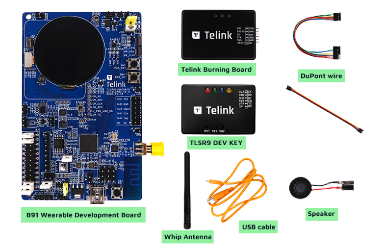
For details, please refer to Wearables - Telink wiki
Software Environment
Environment Introduction
Project Import
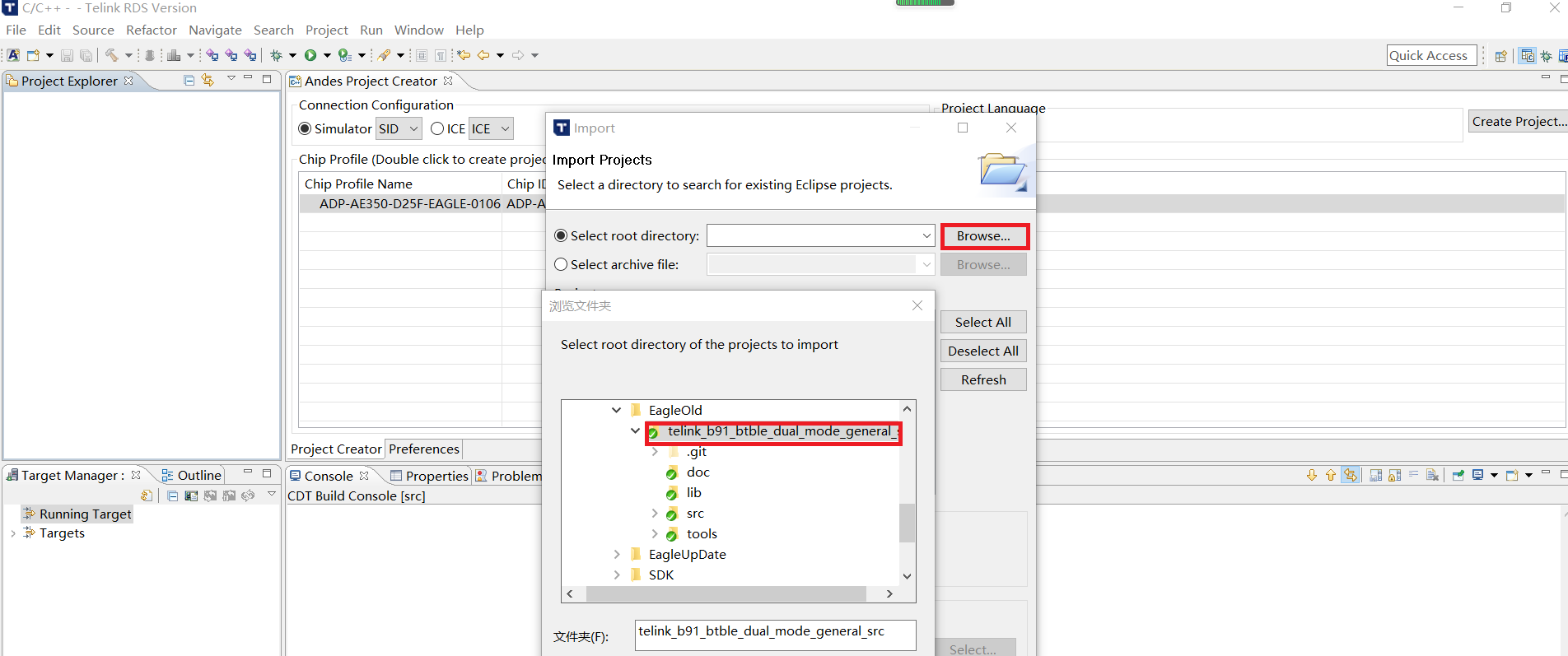
Click the File option, click import, and select Existing Project into Workspace.

Click Browse, and select the project that has downloaded. Click Finish, a project is imported successfully.
Compilation steps

The compile output files are in the src\_TLKAPP_GENERAL_\output directory.
Software Tools
Burning Tool
The following is the burner of Telink. The File option can select the bin file to be burned. After selecting the file, use the Download option to download the bin file. After the burning is completed, press the Reset button to restart the device.
Download debugging tools: Burning and Debugging Tools for all Series
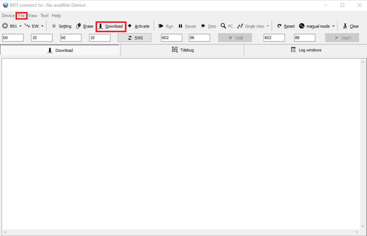
Debug Tool
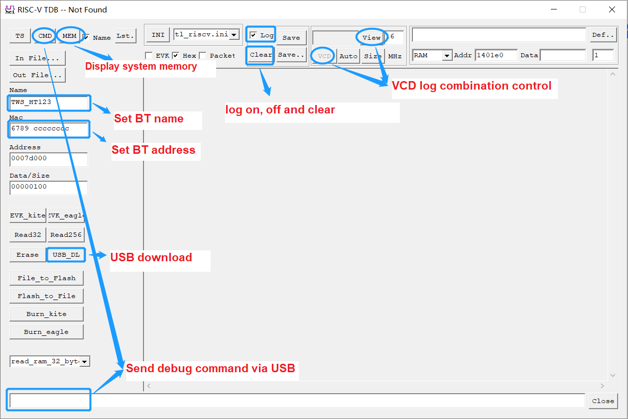
The USB tool provides debugging, downloading and log tracing capabilities. Before using USB, you need to enable the UDB device class provided by Telink, and keep the device ID consistent with the ID configured by the current tool.
Open the USB tool provided by Telink, enable the USB function in the SDK, and connect the USB device. There are three ways to debug:
- View the variables, through "MEM", view the value of the system variables;
- Send a command, type a command starting with 11 in the "CMD" or in the edit field below and press the Enter key.
- Waveform playback, open the VCD function in UDB, click VCD, it will record the timing reversal level, after the user stops, click "View" to view the running timing.
Two download methods are as below:
- USB download, you need to enable UDB, click "In File ..." to select the file with download, click "USB_DL" to download the file, then the tool will automatically write the device name and device address of the BT.
- EVK download, you need to check "EVK", then connect the burn tool (EVK) provided by Telink, click "Burn_eagle" to download the firmware.
For log tracking, you need to check "Log" to view the system operation log on the log panel; click "Clear" to clear all logs on the display panel.
Test Tool
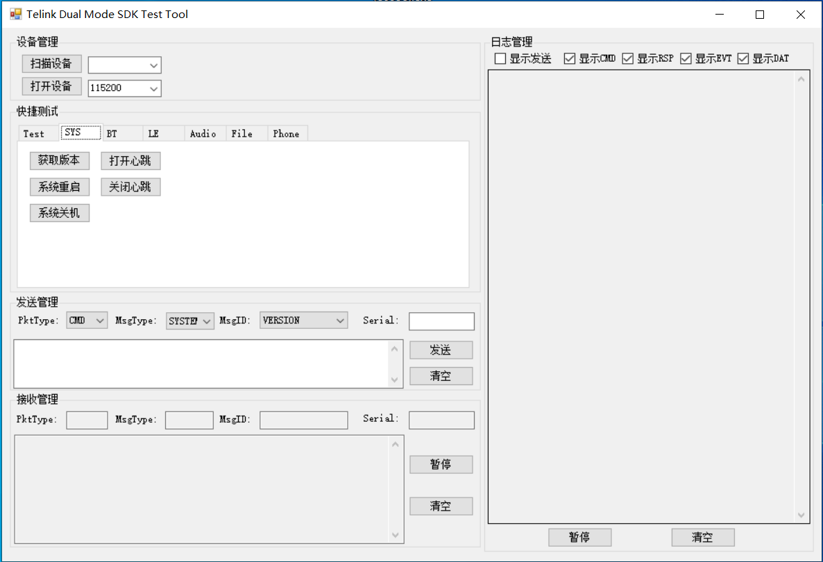
To facilitate user development, Telink provides a set of serial communication software (DualModeSDKTestTool.exe) based on Telink proprietary protocol, which is released with the SDK. Through this tool, combined with the SDK and development version provided by Telink, users can perfectly experience the product form created by Telink for users.
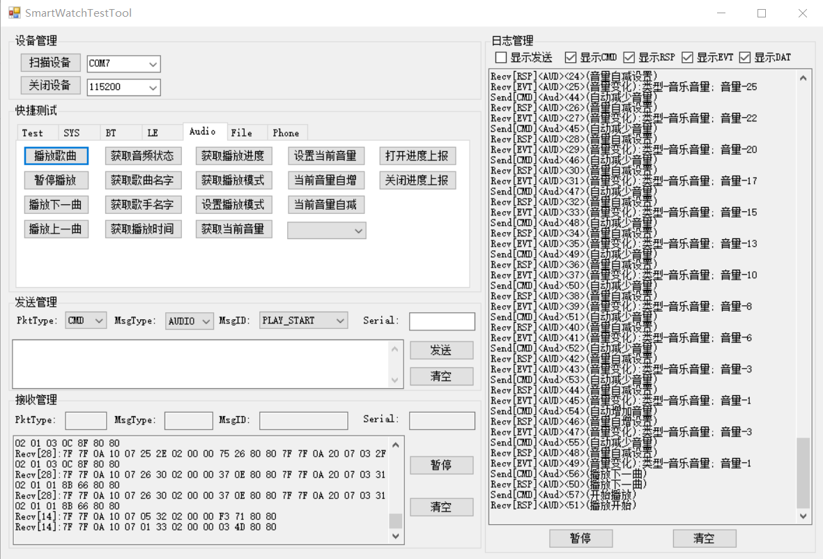
Telink provides the host computer tool for dual-mode SDK, which is applicable to the app/tlkapp_general project in dual-mode SDK. The tool is divided into five parts, namely, device management, quick test, sending management, receiving management and log management. The following briefly introduces the functional features and usage matters of the tools combined with the above figure.
Device Management, which provides options to scan, turn on and turn off devices. When the user opens the tool for the first time, the system will scan the serial device by default and select the first scanned device. If a new device is connected, the user can scan the device and then select the corresponding device to open. Note that the current communication method of the SDK is serial communication, and the serial port baud rate is 115200.
Quick Test, which provides a wrapped message sending button based on the communication protocol, allows users to control the operation of the SDK directly by clicking the button. There are seven sub-items here:
- Test, special message for testing, which will not participate in the official SDK application. It provides quick operations such as phonebook stress testing, switching between USB device classes, and prompt tone testing;
- Sys, provides an access interface for system messages, including version number acquisition, device restart, heartbeat control, etc.;
- BT, provides the management interface of classic Bluetooth, including Bluetooth query, connection, disconnection, and acquisition of pairing list that users care about;
- LE, used to provide a management interface for Bluetooth low energy, temporarily undefined;
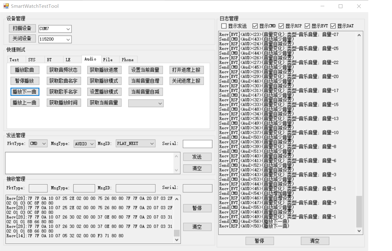
- Audio, provides audio access and control interfaces, including setting volume, obtaining audio status, etc.;
- File, provides file access and control interfaces, including file transfer, list management, etc.;
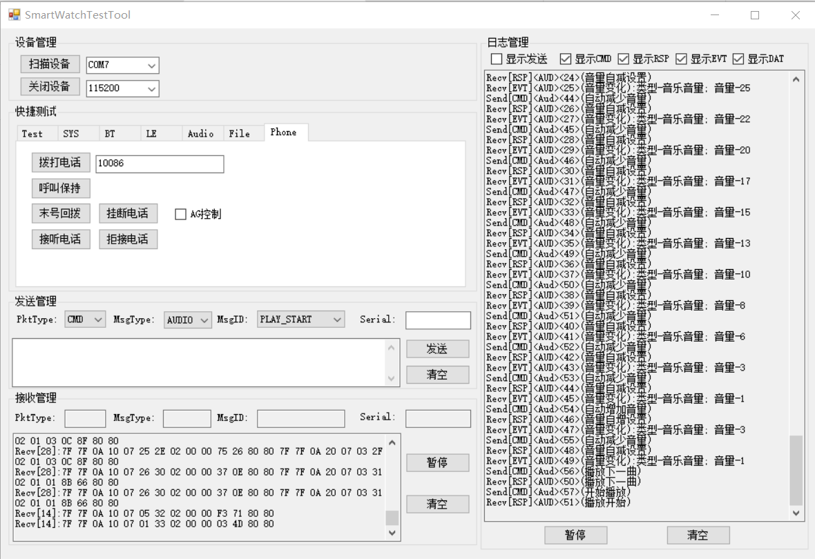
- Phone, provides phone-related interfaces, including making calls, turning off calls, etc..
Sending management, which provides a send-related management and control interface, where users can modify sending commands and parameters.
Receiving management, displays the received packets for easy debugging.
Log management, management of logs.
- Display sending, display and parse the sending data packets;
- Display CMD, parse and display the received CMD data packets;
- Display RSP, parse and display the received RSP data packets;
- Display EVT, parse and display the received EVT data packets;
- Display DAT, parse and display the received DAT data packets;
- Pause/Start, control whether the logs are displayed, after the pause, the newly generated log will be lost;
- Clear, clear all existing logs.
Debug Methods
Crash Problems
(1) Problem Category
During the development process, common crash problems include:
- High-priority interrupts access functions in flash: to ensure efficient execution of important logic and avoid the impact of operating flash on important timing, some functions will be placed in RAM during system design. At present, the priority of flash operation safety is 1 and 0, and the priority of important timing is 2 or 3. Therefore, if the built-in flash access function is called in a high-priority interrupt, it will cause flash timing errors, thus causing the chip to run wrong;
- Memory out-of-bounds: a common problem, our compiler will report warnings for some array out-of-bounds behaviors, so users need to avoid warnings as much as possible;
- Illegal access: a common problem, no further details.
(2) Debug Methods
Variable trace debugging: as shown below, you can define system variables and locate and track layer by layer. When using this method, you should start with the high-priority interrupt function first, because the high-priority interrupt may interrupt the low-priority interrupt at any time.
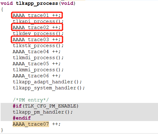
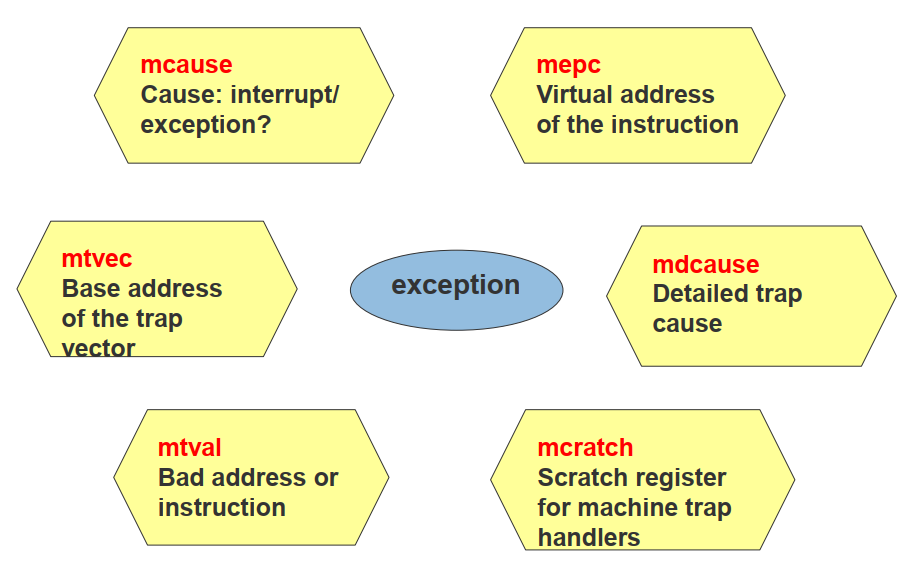
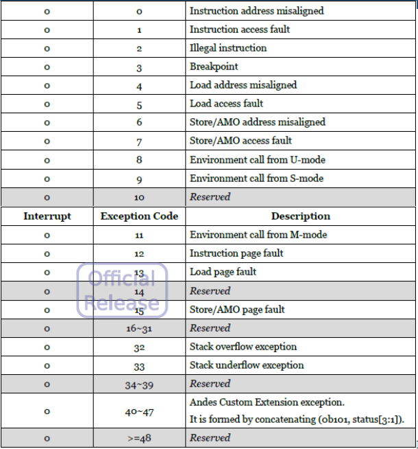
System exception indication: turn on the "IRQ_DEBUG_ENABLE" switch, when an exception occurs, read the value inside the except_handler_b, in which we first determine the cause of the failure mcause (cause field), then check the current interrupt number irq_src, and then through mepc (pc field) to locate the specific place where the problem occurs.
(3) Security Strategy
In order to ensure that the system automatically detects and resets under abnormal conditions, the user needs to turn on "TLK_CFG_WDG_ENABLE" to enable the watchdog function.
Stack Overflow
Users can turn on the "TLKAPI_CHIP_STACK_CHECK_ENABLE" switch and turn on the log at the same time. Then the system will check the current stack depth at regular intervals.
- tlkapi_chip_stackCheck: a stack detection function, which requires a circular call to the interface after calling Init;
- tlkapi_chip_stackDepth: obtain the stack depth;
- tlkapi_chip_stackOverflow: determine if the stack is overflow.
Test Trace
Users can choose to use the USB debugging method and the GPIO analog serial debugging method, before using the system debugging, users need to open the "TLK_CFG_DBG_ENABLE" switch:
- For USB debugging method, users need to open the USB function and select the UDB device class first, working with Telink's USB host computer software, and check "log".
- For GPIO analog serial port, users need to close the USB, use the third-party serial port tool and PC software, connect the RX of the serial port tool to the GPIO_PD5 of the development board, and adjust the baud rate to 1000000.
For better convenience, the system divides the output debugging information into five types, warning, information, trace, error, and exception, each with corresponding macro switches, and users can turn on and off one or more types of logs individually.
Test Experience
Test Preparation
Matched SDK, board and tools.
Test Scenarios
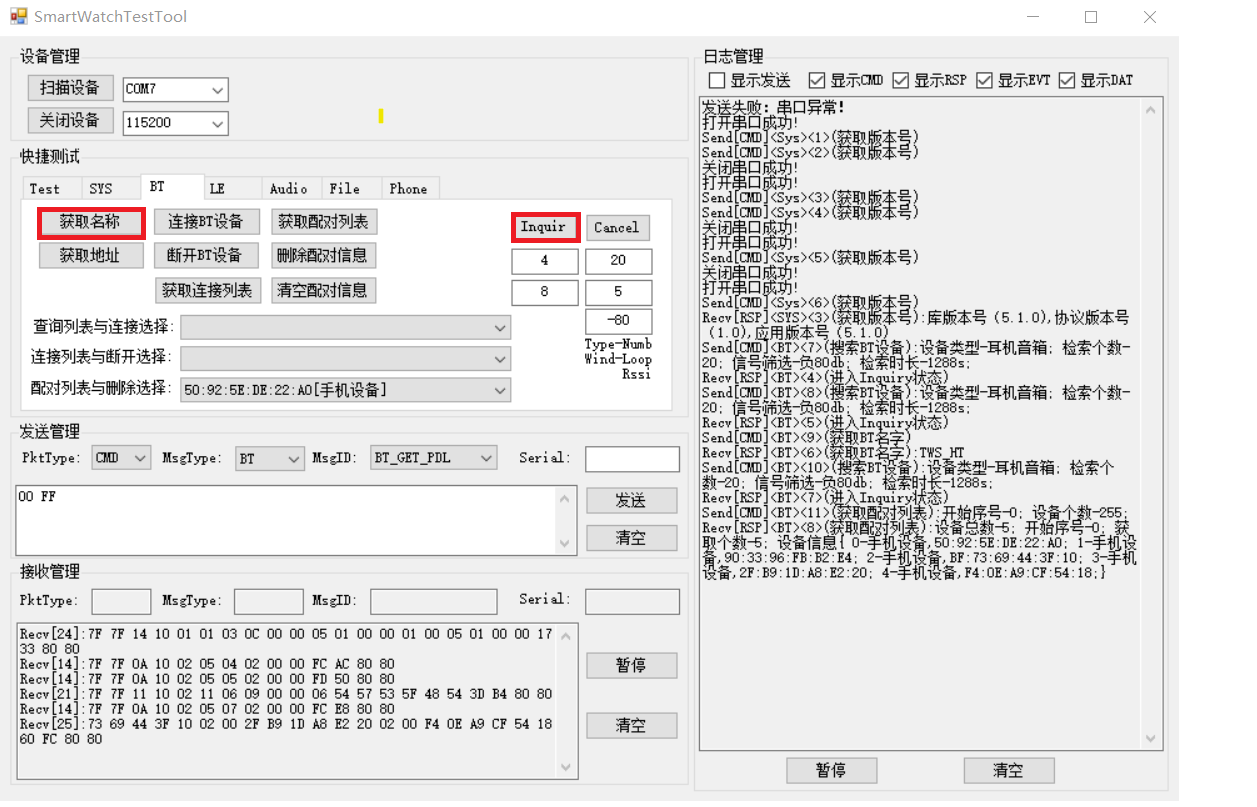
- BT inquiry experience
Clicking Inquiry to start discovering surrounding Bluetooth devices, After that, you can also query the name of the discovered Bluetooth devices by obtaining the name.
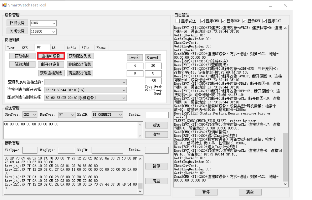
- BT connection experience
Select a device from the discovered devices and click Connect to connect BT device.
- Music playback experience
Music playback is to play local music without connecting a Bluetooth device. Before playing, you need to confirm whether the local device has stored music. If the music is stored, directly operate the above music buttons to control the music playback, pause, previous or next track, etc.
- Headphone music experience
For headset music, you need to complete the Bluetooth connection first, and switch the host tool to Audio. Click play, the music will play; click the volume operation, there will be volume query, adjustment, etc.; click pause play, the music will stop; click play next, it will switch the music to the next play; click play previous, it will switch the music to the previous play. Various functions such as the above are not introduced here.
- Call experience
The headphone requires a Bluetooth connection before making a call. Click to open the Phone and enter the phone number to be dialed. Click to make a call, it will start the phone call function. At present, it supports the functions of calling back the last number, answering the call, rejecting the call and hanging up the call.
Structure Design
The purpose of the SDK is to create a user-friendly, stable, comfortable and convenient solution that encapsulates the functionality and logic of user concerns in a structured way, minimizing the workload of secondary development for the user. Therefore, the design of the SDK always revolves around the two perspectives of hierarchical structure and modularization of functions.
Hierarchical, that is, the code is designed in layers in logic and function, and the layers are stacked to implement strict coupling management within the layers and scheduling control between the layers to avoid coupling calls within the layers and nested usage logic between the layers, thus ensure the readability, portability and stability of the code to the greatest extent.
Modularization, that is, encapsulating and managing interfaces with similar logic, and then forming many modules, ensuring that each module within the hierarchy is not coupled, thus greatly improving the scalability of the code. At the same time, in order to facilitate the user's understanding and use, the system is realized at a higher level, with the underlying module as the unit, and each module with similar functions is integrated, thus realizing a complete functional body with specific functional properties (in that layer the functional body is also a module belonging to that layer).
Design Overview
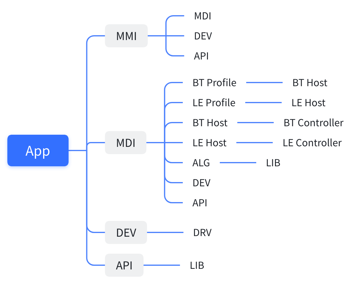
The overall design of the SDK is clear, with no or little coupling between the layers. Each layer in the SDK can be divided into three main categories according to the system logic and design features, namely the protocol stack, the adaptation layer and the application layer.
The stack is the core of the system, and provides a standardized interface for Bluetooth to establish communication and data interaction. The Bluetooth protocol stack is designed exactly according to the logic described in the SPEC provided by the Bluetooth Special Interest Group (SIG), and is divided into three levels: controller, host and profile. The Controller is a hardware-oriented basic control platform that interacts with peer devices in real time, the upper layer is the logic of the Host layer that interacts through HCI; the Host layer is the interface layer that controls the Controller, performs data interaction according to user behavior, and receives events reported by the Controller at the same time; Profile is a standardized module designed for user-specific functions and for orderly and stable communication between platforms.
The adapt layer is provided by Telink to facilitate users' secondary development and provide convenient and stable general-purpose interfaces or simple modules, which can greatly improve users' development efficiency. The Adapt layer is divided into five parts: DRV, LIB, DEV, ALG and API. DRV (Drivers) mainly provides the basic driver of the chip and the underlying operating interface of complex devices; DEV (Devices) mainly provides the interface for direct access and control of devices; LIB (Library) is mainly the system to some users do not care about the algorithm or modular program for the packaging, the formation of only expose the user may use to the interface; ALG (Algorithm) is the algorithm layer for the chunk packaging, to provide the user visualization interface; API (Application Interface) is the system provides, simple and efficient general-purpose interface.
The user layer is an application routine provided by Telink for the physical product. The user layer mainly integrates a module with a certain function, then combines multiple modules to form a complete functional body, and finally combines multiple functional bodies in an orderly manner to perform a perfect application routine. According to the hierarchical relationship, the application layer can be divided into MDI (Module Interface), MMI (Man-Machine Interface) and APP (Application): MDI, that is, module design interface, integrates and manages a single function and provides a set of more concise interaction interfaces, such as BT connection, query, reconnection, etc.; MMI, that is, human-machine interaction interface, is a simple application DEMO formed by encapsulating and centrally managing functions or functional modules belonging to a certain type, and providing the interaction interface for the APP layer; APP, that is, an application program, is a complete version of the application demo with certain product functions and forms, users can directly expand or add logic that meets their needs on this basis to form their own products.
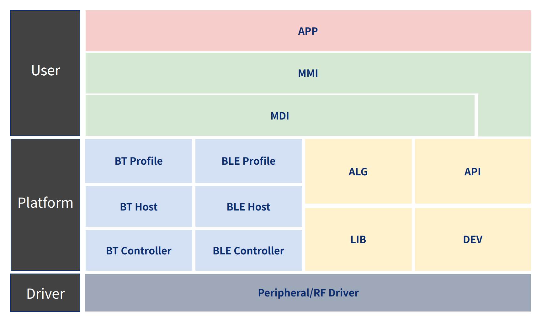
Specifically it includes the following parts:
- APP: Application
- MMI: Man-Machine Interface
- MDI: Module Design Interface
- ALG: Algorithm
- API: Application Interface
- LIB: Library
- DEV: Devices
- DRV: Drivers
Operation Flow
Currently, the SDK is designed in a single-threaded manner, that is, there is only one main task in the system, and the main task is executed in a loop, and at the same time, it cooperates with the interrupt mode to handle emergencies. Under the main task of the system, there are multiple subtasks, and each subtask is a separate running subject. The subtasks are mainly responsible for handling the functions and logic of the corresponding level, and the subtasks cooperate with each other and run alternately, thus forming the operation form of the whole system.
In the system, each subtask is designed according to the principle of demand-oriented execution and following the timer scheduling. Any module in the subtask wants to execute, it needs to meet one of the two conditions, that is, an external request comes in (either a user request or a hierarchical call) or a timer is reached. Each module in the subtask is designed with a bit field variable to record that there is a demand in the subtask that is busy or waiting for a certain state to arrive, and that timer will not be released until the demand is executed effectively or is cancelled.
Each subtask contains one or more modules, and the scheduling of each module is based on the time slice and work queue of the subtask, which means that users only need to understand the operation mechanism of any subtask to understand the operation principle of the whole system. Based on the time slice scheduling method, each subtask is scheduled to perform internal module scheduling when the time comes, which can reduce the utilization rate of the MCU, reduce the blocking of the system, and improve the performance of the system.
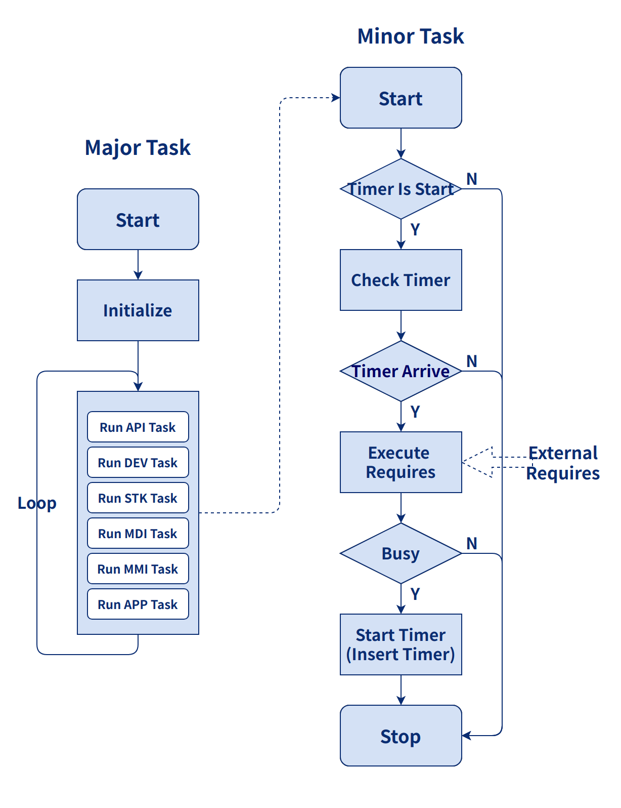
Hierarchy
The following figure shows the calling relationship between various levels in the system, and cooperates with the system framework structure diagram, so that users can better understand the operating mechanism of the system and facilitate secondary development.
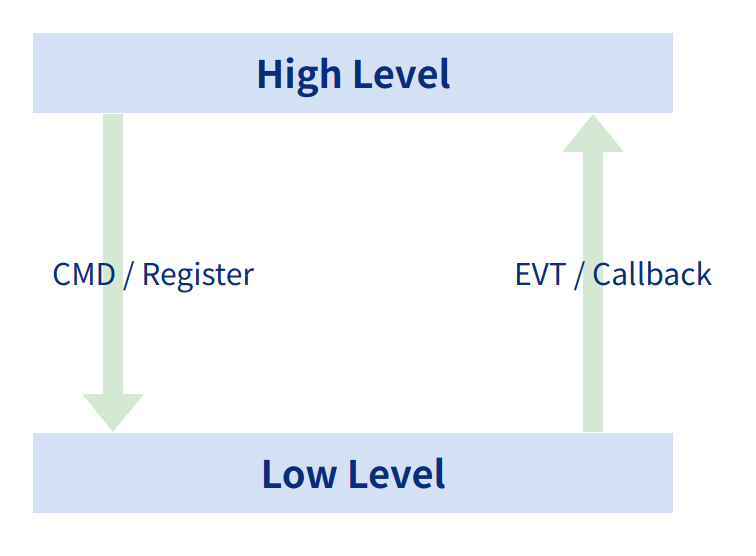
In addition, it is necessary to highlight two kinds of relationships between layers: one is downward logical interaction; the other is upward logical communication. The downward logical interaction is mainly that the upper layer can directly control the lower layer by issuing commands or directly calling the interface provided by the lower layer; the upward logical communication is mainly that the lower layer reports the data or state changes it gets to the upper layer through the callback interface registered by the upper layer or in the form of events, so as to synchronize the data and state of the upper and lower layers.
Communication Protocols
In order to facilitate users to experience and use this system, the system contains a set of private communication protocols, and with the proprietary PC tools, users can directly use the application demo provided by the SDK to experience the full functionality of the system.
The communication protocol inside the system is proprietary to Telink, with high stability and scalability. The system adopts serial communication mode, and all control and processing logic are in the APP and MMI layers in the application layer. For more information about the protocol, please refer to the relevant protocol documentation.
Common interfaces
API Overview
API is a set of general-purpose application and algorithm interfaces provided for the system or users. Users can access system resources and quickly realize their own functions by calling the interfaces provided in the API. As shown in the figure below, the API layer provides users with related interfaces such as log management, memory management, cache access, file system and scheduler.
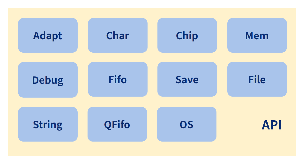
The following is a detailed description of the interfaces of each module in the API for functions, interfaces, and usage rules:
- Function description, mainly introduces some of the most basic functions and logic flow of the module.
- Rule constraints, restrictive conditions that exist in the process of using the basic functions.
- Interface description, a detailed description of each component inside the module, including four parts, module name, module basic elements (such as: data structure, global variable, macro definition, interface function, etc.), basic element definition and basic element detailed explanation.
Adapt Interface Design
Function Description
The Adapt is a single-threaded, timed scheduling and work queue related control interface for the entire system operation. Currently, all task scheduling in the system adopts the method of timing operation and queue execution to ensure the efficiency of system execution to the greatest extent and achieve the purpose of reducing the idle time of the system to the greatest extent.
The Adapt is a very core interface of the SDK, which supports the normal operation of the entire SDK. Each module implements corresponding functions or requirements by using timed scheduling and work queues.
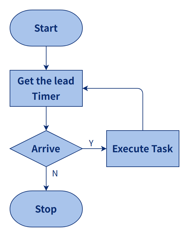
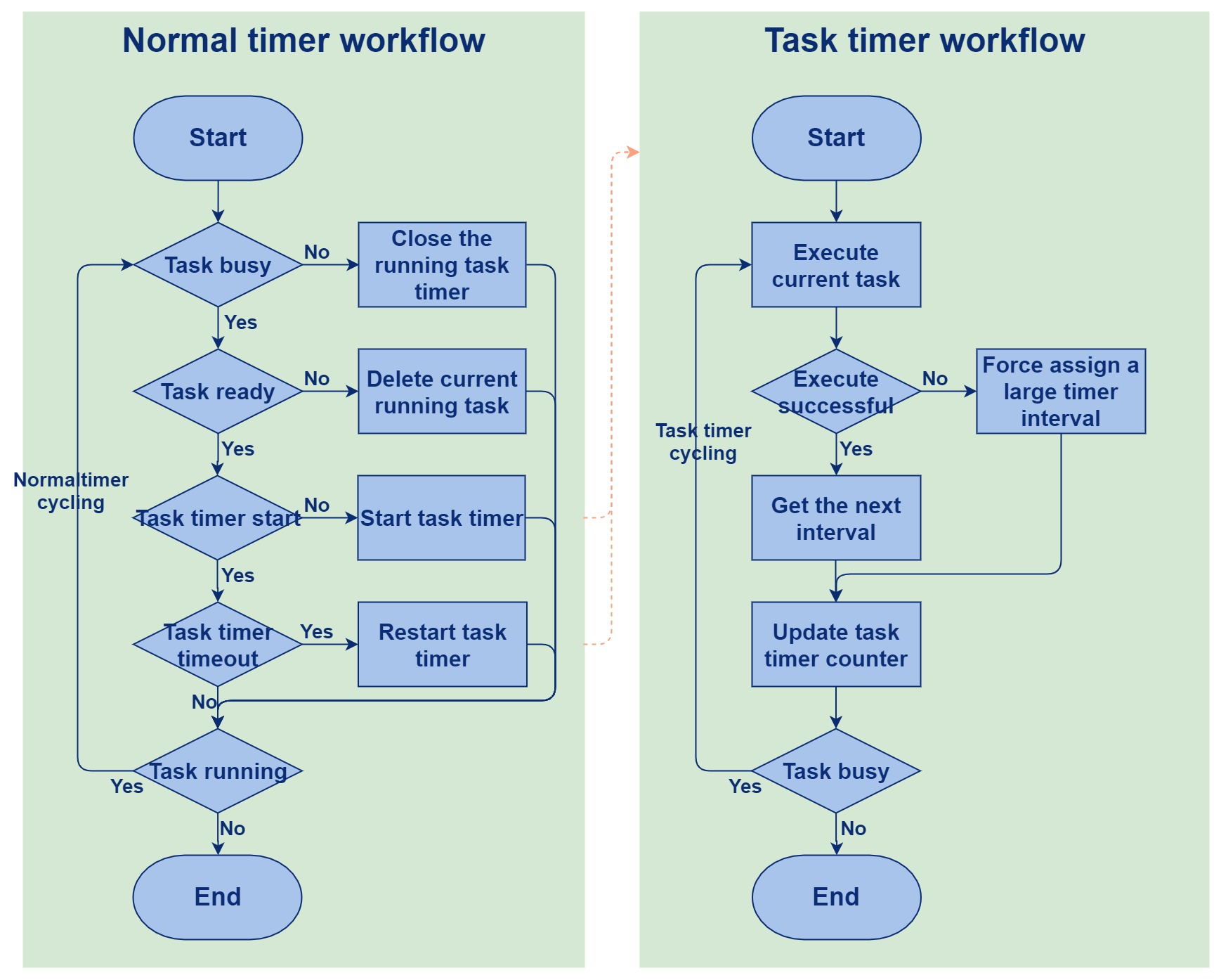
The following figure shows the execution flow of Timer. After the application is started, each layer will start its own timer management list, and the timer for each executed action will be inserted into the list. The program will iterate through the timer list during the execution of the loop, determine whether the timers in the timer list Arrive, the action corresponding to the Arrived timer will be executed, and the execution will be completed and exited, otherwise it will exit directly and query the next timer in the timer list.
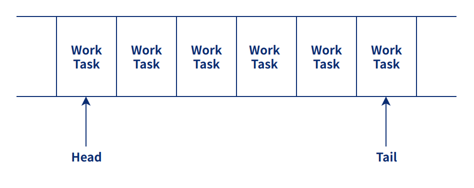
The figure below is the list of work tasks, each layer has its own task list, which is used to handle events that are not very time-critical. When the task list is traversed, all the events in the task list will be processed. It can be used together with timer or separately.
Rule Constraints
When using the adapt interface, users need to pay attention to the following:
- Timing and queue related interfaces need to be initialized before use;
- Timing and queue scheduling process, with insert or append there must be remove, otherwise a system exception will be raised.
- The maximum time interval for timing is 134s, beyond which the timing will be invalid.
- Timer and queue callbacks in which the user only needs to return true if they want to reuse it, otherwise timer will stop automatically.
- Timing uses software timer, which can be affected by interrupts, blocking or low power consumption, thus triggering deviations in timing accuracy.
Interface Description
The Adapt interface is designed as follows:
Macro definition:
Maximum Timeout time:
#define TLKAPI_TIMEOUT_MAX (0x07FFFFFF)
Minimum Timeout time:
#define TLKAPI_TIMEOUT_MIN 100
Data structure:
Define the data structure of the Timer control:
struct tlkapi_timer_s{
        uint32 arrival;
        uint32 timeout;
        void  *pUsrArg;
        TlkApiTimerCB timerCB;
        struct tlkapi_timer_s *pNext;
};
- arrival: count time of Timer
- timeout: Timeout time of Timer
- *pUsrArg: usage parameters of the CB function of Timer
- timerCB: callback function of Timer
- *pNext: data structure pointer of Timer
Define the data structure of the Proc control:
struct tlkapi_procs_s{
        void *pUsrArg;
        TlkApiProcsCB procsCB;
        struct tlkapi_procs_s *pNext;
};
- *pUsrArg: process usage parameters after the task occurs
- *pNext: data structure pointer of Timer Proc
Define the data structure of Adapt:
typedef struct{
        tlkapi_procs_t *pProcsList;
        tlkapi_timer_t *pTimerList;
}tlkapi_adapt_t
- pProcsList: tasks list to be processed
- pTimerList:Timer time list to be processed
Type definition:
Define the data structure of the Timer list:
typedef struct tlkapi_timer_s tlkapi_timer_t
Define the data structure of the Procs list:
typedef struct tlkapi_procs_s tlkapi_procs_t
Define the callback handler function for Procs:
typedef bool(*TlkApiProcsCB)(tlkapi_procs_t *pProcs, void *pUsrArg)
Define the callback handler function for Timer:
typedef bool(*TlkApiTimerCB)(tlkapi_timer_t *pTimer, void *pUsrArg)
Interface definition:
Initialize the list of procs and Timer:
int tlkapi_adapt_init(tlkapi_adapt_t *pAdapt)
The data processing function of Procs list and Timer list, through this function, each data inserted into Proc list and Timer list is processed by callback function:
void tlkapi_adapt_handler(tlkapi_adapt_t *pAdapt)
Filling of Timer data, through this interface, you can configure the TimerCB, parameters and TimeOut that need to be processed:
int tlkapi_adapt_initTimer(tlkapi_timer_t *pTimer, TlkApiTimerCB timerCB, void *pUsrArg, uint32 timeout)
Filling of Proc data, through this interface, you can configure the ProcCB and parameters that need to be processed:
int tlkapi_adapt_initProcs(tlkapi_procs_t *pProcs, TlkApiProcsCB procsCB, void *pUsrArg)
Remove the target Timer from TimerList:
void tlkapi_adapt_deinitTimer(tlkapi_adapt_t *pAdapt, tlkapi_timer_t *pTimer)
Remove the target Proc from ProcList:
void tlkapi_adapt_deinitProcs(tlkapi_adapt_t *pAdapt, tlkapi_procs_t *pProcs)
Determine if the Timer is in the Timer list:
bool tlkapi_adapt_isHaveTimer(tlkapi_adapt_t *pAdapt, tlkapi_timer_t *pTimer)
Determine if the Proc is in the Proc List:
bool tlkapi_adapt_isHaveProcs(tlkapi_adapt_t *pAdapt, tlkapi_procs_t *pProcs)
Add the Procs to the Procs List:
int tlkapi_adapt_appendProcs(tlkapi_adapt_t *pAdapt, tlkapi_procs_t *pProcs)
Remove the Procs from the Procs List:
int tlkapi_adapt_removeProcs(tlkapi_adapt_t *pAdapt, tlkapi_procs_t *pProcs)
Update the timeout value of the timer in the timer list:
int tlkapi_adapt_updateTimer(tlkapi_adapt_t *pAdapt, tlkapi_timer_t *pTimer, uint32 timeout)
Insert a new Timer into the Timer list:
int tlkapi_adapt_insertTimer(tlkapi_adapt_t *pAdapt, tlkapi_timer_t *pTimer)
Remove the Timer from the Timer list:
int tlkapi_adapt_removeTimer(tlkapi_adapt_t *pAdapt, tlkapi_timer_t *pTimer)
Query the time difference between the current time and Timeout:
uint32 tlkapi_adapt_timerInterval(tlkapi_adapt_t *pAdapt)
Get the first timer in the Timer list:
tlkapi_timer_t *tlkapi_adapt_takeFirstTimer(tlkapi_adapt_t *pAdapt)
Print Timer:
void tlkapi_adapt_printTimer(tlkapi_adapt_t *pAdapt)
Check if the Timer is in the Timer list:
void tlkapi_adapt_checkTimer(tlkapi_adapt_t *pAdapt, tlkapi_timer_t *pTimer)
Debug Interface Design
Function Description
Debug is an interface prepared for application debugging with multiple layers of control and hierarchical control.
Debug has three layers of control switches: interface layer general switch, which can be configured with macro enable switch to directly turn off all debug interfaces; interface layer sub-switch, where users can turn on and off the relevant level of log; user layer switch, where users can dynamically control whether log is output or not by simply entering the corresponding flag bits.
Another feature of Debug is the hierarchical control mechanism. The system divides the debugging interface into trace (TRACE), information (INFO), warning (WARN), error (ERROR), exception (FATAL) and so on according to the severity level from low to high.
In addition, the system also provides multiple sets of output interfaces for Debug, currently supported by USB data, GPIO analog serial output two ways.
Rule Constraints
In functions with high priority (priority higher than 1), do not call the debug interface, otherwise there will be a risk of crash.
Interface Description
The debug interface is designed as follows.
Macro definition:
Define the path of the log transfer through the UDB:
#define TLKAPI_DEBUG_METHOD_UDB 1
Define the path of the log transfer through the GPIO:
#define TLKAPI_DEBUG_METHOD_GPIO 2
Define the path of the log transfer through the UART:
#define TLKAPI_DEBUG_METHOD_UART 3
Define the PIN of the GPIO:
#define TLKAPI_DEBUG_GPIO_PIN GPIO_PD5
Define the serial port baud rate:
#define TLKAPI_DEBUG_BAUD_RATE 1000000
Define the log to be printed at the level of WARNING:
#define TLKAPI_DBG_WARN_FLAG 0x02
Define the log to be printed at the level of INFO:
#define TLKAPI_DBG_INFO_FLAG 0x04
Define the log to be printed at the level of TRACE:
#define TLKAPI_DBG_TRACE_FLAG 0x08
Define the log to be printed at the level of ERROR:
#define TLKAPI_DBG_ERROR_FLAG 0x10
Define the log to be printed at the level of FATAL:
#define TLKAPI_DBG_FATAL_FLAG 0x20
Define the log to be printed at the level of ARRAY (more data to be processed):
#define TLKAPI_DBG_ARRAY_FLAG 0x40
Define the log to be printed at the level of ASSERT:
#define TLKAPI_DBG_ASSERT_FLAG 0x80
Define output all logs:
#define TLKAPI_DBG_FLAG_ALL 0xFE
Define the log printing function of warning:
#define tlkapi_warn tlkapi_debug_warn
Define the log printing function of info:
#define tlkapi_info tlkapi_debug_info
Define the log printing function of trace:
#define tlkapi_trace tlkapi_debug_trace
Define the log printing function of fatal:
#define tlkapi_fatal tlkapi_debug_fatal
Define the log printing function of error:
#define tlkapi_error tlkapi_debug_error
Define the log printing function of array:
#define tlkapi_array tlkapi_debug_array
Define the log printing function of assert:
#define tlkapi_assert tlkapi_debug_assert
Define the function of sprint:
#define tlkapi_sprintf tlkapi_debug_sprintf
Define the header of the WARN level log:
#define TLKAPI_WARN_HEAD "<WARN>"
Define the header of the INFO level log:
#define TLKAPI_INFO_HEAD "<INFO>"
Define the header of the TRACE level log:
#define TLKAPI_TRACE_HEAD "<TRACE>"
Define the header of the FATAL level log:
#define TLKAPI_FATAL_HEAD "<FATAL>"
Define the header of the ERROR level log:
#define TLKAPI_ERROR_HEAD "<ERROR>"
Define the header of the ARRAY level log:
#define TLKAPI_ARRAY_HEAD "<ARRAY>"
Define the header of the ASSERT level log:
#define TLKAPI_ASSERT_HEAD "<ASSERT>"
Define the output length of the log:
#define TLKAPI_DEBUG_ITEM_SIZE 144
Define the output number of the log:
#define TLKAPI_DEBUG_ITEM_NUMB 16
Interface definition:
Initialize fifo and enable GPIO:
int tlkapi_debug_init(void)
Reset parameters, used by UDP:
void tlkapi_debug_reset(void)
Take out the data in the FIFO and send:
void tlkapi_debug_process(void)
Function interface for handling log output with multiple parameters:
int tlkapi_debug_sprintf(char *pOut, const char *format, ...)
Output warn level log:
void tlkapi_debug_warn(uint flags, char *pSign, const char *format, ...)
- flag: log level
- pSign: module labels, such as A2DP, etc.
- format: enter log content
Output info level log:
void tlkapi_debug_info(uint flags, char *pSign, const char *format, ...)
- flag: log level
- pSign: module labels, such as A2DP, etc.
- format: enter log content
Output Trace level log:
void tlkapi_debug_trace(uint flags, char *pSign, const char *format, ...)
- flag: log level
- pSign: module labels, such as A2DP, etc.
- format: enter log content
Output FATAL level log:
void tlkapi_debug_fatal(uint flags, char *pSign, const char *format, ...)
- flag: log level
- pSign: module labels, such as A2DP, etc.
- format: enter log content
Output ERROR level log:
void tlkapi_debug_error(uint flags, char *pSign, const char *format, ...)
- flag: log level
- pSign: module labels, such as A2DP, etc.
- format: enter log content
Output ARRAY level log:
void tlkapi_debug_array(uint flags, char *pSign, char *pInfo, uint08 *pData, uint16 dataLen)
- flag: log level
- pSign: module labels, such as A2DP, etc.
- format: enter log content
Output ASSERT level log:
void tlkapi_debug_assert(uint flags, bool isAssert, char *pSign, const char *format, ...)
- flag: log level
- pSign: module labels, such as A2DP, etc.
- format: enter log content
Send log data:
void tlkapi_debug_sendData(char *pStr, uint08 *pData, uint16 dataLen)
Send character data:
void tlkapi_debug_sendU08s(void *pStr, uint08 val0, uint08 val1, uint08 val2, uint08 val3)
Send short integer data:
void tlkapi_debug_sendU16s(void *pStr, uint16 val0, uint16 val1, uint16 val2, uint16 val3)
Send integer data:
void tlkapi_debug_sendU32s(void *pStr, uint32 val0, uint32 val1, uint32 val2, uint32 val3)
Send status:
void tlkapi_debug_sendStatus(uint08 status, uint08 buffNumb, uint08 *pData, uint16 dataLen)
Delay printing:
void tlkapi_debug_delayForPrint(uint32 us)
MEM interface design
Function Description
The MEM interface is a dynamic memory management interface provided by the system, including the commonly used interfaces malloc, free, remalloc, etc.
The system provides two sets of interfaces, the system memory allocation management interface and the general memory allocation management interface. Users can use the general memory allocation management interface to dynamically define their own memory blocks to prevent problems that cause the system to work abnormally due to insufficient memory or memory fragmentation.
Rule Constraints
The currently defined system memory management interface can only be used in single-threaded cases. If users want to use it properly in multi-threaded cases, they can enable the OS during initialization, after which the system will automatically add critical area protection during allocation and release.
Interface Description
The mem interface is designed as follows.
Type definition:
Define the type of tlkapi_mem_t as unsigned long:
typedef ulong tlkapi_mem_t
Data structure:
Define memory unit:
typedef struct{
        uint32 prev;
        uint32 next;
        uint32 size:31;
        uint32 used:1;
}tlkapi_mem_unit_t
- prev: points to the previous block address of the current memory unit
- next: points to the next block address of the current memory unit
- size: define size
- used: define whether to be used
Define control data for memory:
typedef struct{
        uint08 isEnOs;
        uint08 reserv0;
        uint16 reserv1;
        uint32 totalSize;
        uint32 unuseSize;
        uint08 *pBaseAddr;
}tlkapi_mem_ctrl_t
- isEnOs: whether there is enable OS
- totalSize: memory size
- unuseSize: memory size not currently in use
- *pBaseAddr: base address of memory
Variable definitions:
Define the global control variables for the memory pool:
volatile tlkapi_mem_t sTlkApiMemGlobal
Interface definition:
Allocate a block of memory from the memory pool:
void *tlkapi_malloc(uint32 size)
Allocate a block of memory from memory pool and clear it:
void *tlkapi_calloc(uint32 size)
Allocate memory from the memory pool, adjust the memory size, and return memory with a more suitable size:
void *tlkapi_realloc(void *ptr, uint32 size)
Release memory:
void tlkapi_free(void *ptr)
Print the contents of a block of memory:
void tlkapi_printMem(void)
Initialize the memory pool:
tlkapi_mem_t tlkapi_mem_init(bool osIsEn, uint08 *pBuffer, uint32 buffLen)
The deinit of the memory pool, to clear the memory:
void tlkapi_mem_deinit(tlkapi_mem_t mem)
Clear the memory pool:
void tlkapi_mem_clean(tlkapi_mem_t mem)
Execute the function of printing a block of memory:
void tlkapi_mem_print(tlkapi_mem_t mem)
Allocate a block of size memory from the memory pool:
void *tlkapi_mem_malloc(tlkapi_mem_t mem, uint32 size)
Allocate a block of size memory from the memory pool and clear it:
void *tlkapi_mem_calloc(tlkapi_mem_t mem, uint32 size)
Reallocate a block of memory suitable for size from the memory pool:
void *tlkapi_mem_realloc(tlkapi_mem_t mem, void *ptr, uint32 size)
Release a block of memory in the memory pool:
int tlkapi_mem_free(tlkapi_mem_t mem, void *ptr)
OS Interface Design
Function Description
TBD
Rule Constraints
TBD
Interface Description
TBD
File Interface Design
Function Description
The file system is mainly the operation interface provided by the SDK to facilitate users to store files. Currently, the file system in the SDK is the FAT32 file system. The SDK can manage files through the FAT file system according to business requirements.
Rule Constraints
When using the file system, note the following matters:
- File access can only be accessed in interrupts or non-interrupts no higher than level 1;
- The opened interface must be closed, otherwise it cannot be completely deleted;
- When encountering a deletion error, you can open the file first, close the file, and then try to delete it again.
Interface Description
The file interface is designed as follows.
Macro definition:
Specify the read access object to read data from a file:
#define TLKAPI_FM_READ 0x01
Specify the write access object to write data to the file:
#define TLKAPI_FM_WRITE 0x02
Open the file, or fail if the file does not exist:
#define TLKAPI_FM_OPEN_EXISTING 0x00
Create a new file, or fail to create if the file exists:
#define TLKAPI_FM_CREATE_NEW 0x04
Create a new file. If the file already exists, it will be truncated and overwritten:
#define TLKAPI_FM_CREATE_ALWAYS 0x08
Open the file if it exists; otherwise, create a new file:
#define TLKAPI_FM_OPEN_ALWAYS 0x10
Open the file to append content to it:
#define TLKAPI_FM_OPEN_APPEND 0x30
Define FCHAR as the type of uint16:
#define FCHAR uint16
Define FCHAR as char type without file system:
#define FCHAR char
Define FIL as empty type without file system:
#define FIL void
Global variable:
Define Fat file system control variables:
FATFS gTlkFileFatFs
Interface definition:
Undefined:
int tlkapi_file_size(FIL *pFile)
Get the length of the file path:
int tlkapi_file_strlen(FCHAR *pPath)
Open file, file path and file mode:
int tlkapi_file_open(FIL *pFile, const FCHAR *pPath, uint08 mode)
Close a file:
int tlkapi_file_close(FIL *pFile)
Move the file operation pointer backward from the current position to the position of ofs:
int tlkapi_file_seek(FIL *pFile, uint32 ofs)
Read data from file:
int tlkapi_file_read(FIL pFile, void buff, uint32 btr, uint32* br)
Write data to file:
int tlkapi_file_write(FIL pFile, const void buff, uint32 btw, uint32* bw)
Open directory file:
int tlkapi_file_opendir(DIR pDir, const FCHAR path)
Close directory file:
int tlkapi_file_closedir(DIR *pDir)
Read directory function:
int tlkapi_file_readdir(DIR pDir, FILINFO fno)
Find the first file in the directory:
int tlkapi_file_findfirst(DIR pDir, FILINFO fno, const FCHAR* path, const FCHAR* pattern)
Find the next file of the current file in the directory:
int tlkapi_file_findnext(DIR pDir, FILINFO fno)
Create a file named path:
int tlkapi_file_mkdir(const FCHAR* path)
Delete the file specified by path:
int tlkapi_file_unlink(const FCHAR* path)
Replace the old filename with the new filename:
int tlkapi_file_rename(const FCHAR* path_old, const FCHAR* path_new)
Mount File System:
int tlkapi_file_mount(const FCHAR* path, uint08 opt)
Create a file system under a specific partition:
int tlkapi_file_mkfs(const FCHAR* path, const void* opt, void* work, uint32 len)
Disk operation function:
int tlkapi_file_fdisk(uint08 pdrv, const uint32 ptbl[], void* work)
Chip Interface Design
Function Description
The chip mainly contains interfaces related to system clock switching and program stack depth detection.
- The clock switching is mainly to provide dynamic clock switching interfaces to meet different operating scenarios. Currently, there are 48M and 96M; 48M is the idle running clock of the system, and 96M is running when the system audio is turned on (need to run a variety of algorithms).
- The stack depth detection is mainly used for real-time dynamic detection, the maximum stack depth used by the current program execution.
Rule Constraints
TBD
Interface Description
The chip interface is designed as follows.
Macro definition:
Define macros that control stack operations:
#define TLKAPI_CHIP_STACK_CHECK_ENABLE 0
Data structure:
Define the system master clock, there are 96M and 48M:
typedef enum{
        TLKAPI_CHIP_CLOCK_96M = 1,
        TLKAPI_CHIP_CLOCK_48M = 2,
}TLKAPI_CHIP_CLOCK_ENUM
Interface definition:
Configure the system main clock and coordinate the frequency of the mainloop:
void tlkapi_chip_switchClock(TLKAPI_CHIP_CLOCK_ENUM clock)
Initialize the top and bottom of the stack:
void tlkapi_chip_stackInit(void)
Query the usage depth of the current stack:
uint tlkapi_chip_stackUsed(void)
Query the total depth of the stack:
uint tlkapi_chip_stackDepth(void)
Query if the stack overflow:
bool tlkapi_chip_stackOverflow(void)
FIFO Interface Design
Function Description
FIFO is the interface for orderly data access to large memory blocks. The system provides functional configurations for overwriting and selective writing:
- The user can open the overwrite read and write to achieve the effect of overwriting the old data when the fifo data is full;
- The user can turn on the partial write function to achieve the effect of writing according to the maximum length that can be written when the fifo space is insufficient.
Rule Constraints
The actual buffer available to the user is 1 smaller than the actual buffer set by the user.
Interface Description
The FIFO interface is designed as follows.
Macro definition:
Define the minimum size of the FIFO:
#define TLKAPI_FIFO_MIN_SIZE 64
Data structure:
Define the data structure of the FIFO:
typedef struct{
        uint08 isCover;
        uint08 isParty;
        uint16 more75L;
        uint16 more90L;
        uint16 woffset;
        uint16 roffset;
        uint16 buffLen;
        uint08 *pBuffer;
}tlkapi_fifo_t;
- isCover: Defines whether the previous data can be overwritten with the newly written data after the fifo is full.
- isParty: Define that only part of the current space of the fifo is left, whether it is possible to write only part of the new data.
- more75L: Mark whether the free space of the current fifo is less than 25%.
- more90L: Mark whether the free space of the current fifo is less than 10%.
- Roffset: The current read offset of the fifo.
- Woffset: The current write offset of the fifo.
- buffLen: The length of the buffer.
- *pBuffer: The address of the buffer.
Interface definition:
Initialize the control structure of the fifo:
int tlkapi_fifo_init(tlkapi_fifo_t *pFifo, uint08 isCover, uint08 isPartly, uint08 *pBuffer, uint16 buffLen)
- pFifo, the control structure of the FIFO.
- isCover, it can be overwritten.
- isParty, is whether to allow only a portion of the data to be written to the fifo if there is not enough space in the fifo.
- pBuffer, is the buffer to be used as the fifo.
Check if the current fifo control structure has been released, and if not, execute the release process:
void tlkapi_fifo_deinit(tlkapi_fifo_t *pFifo)
Empty the control structure of pfifo:
void tlkapi_fifo_reset(tlkapi_fifo_t *pFifo)
Erase the write data of the fifo:
void tlkapi_fifo_clear(tlkapi_fifo_t *pFifo)
Determine whether data in a fifo is empty:
bool tlkapi_fifo_isEmpty(tlkapi_fifo_t *pFifo)
Query how many free buffers are currently unused:
uint16 tlkapi_fifo_idleLen(tlkapi_fifo_t *pFifo)
Query the length of the data stored in the current fifo:
uint16 tlkapi_fifo_dataLen(tlkapi_fifo_t *pFifo)
The length of fifo:
uint16 tlkapi_fifo_buffLen(tlkapi_fifo_t *pFifo)
Determine whether the current fifo usage exceeds 75%:
bool tlkapi_fifo_isMore75(tlkapi_fifo_t *pFifo, uint16 dataLen)
Determine whether the current fifo usage exceeds 90%:
bool tlkapi_fifo_isMore90(tlkapi_fifo_t *pFifo, uint16 dataLen)
Read data from fifo:
int tlkapi_fifo_read(tlkapi_fifo_t *pFifo, uint08 *pBuff, uint16 readLen)
Insert data into fifo:
int tlkapi_fifo_write(tlkapi_fifo_t *pFifo, uint08 *pData, uint16 dataLen)
Read data from fifo in byte form:
int tlkapi_fifo_readByte(tlkapi_fifo_t *pFifo, uint08 *pByte)
Write data from fifo in byte form:
int tlkapi_fifo_writeByte(tlkapi_fifo_t *pFifo, uint08 obyte)
QFIFO Interface Design
Function Description
QFIFO is a queued cache access interface that provides a fixed-length, multi-item ordered access interface. During the initialization process of QFIFO, it is necessary to specify the size and number of items in the fifo. In the system, this type of interface is widely used in the process of audio data access.
The difference between QFIFO and FIFO is that QFIFO is the control of splitting a section of buffer into multiple blocks (the operation unit is block), while the operation unit of FIFO is byte.
Rule Constraints
No constraints at present.
Interface Description
The qfifo interface is designed as follows.
Macro definition:
The size of qfifo:
#define tlkapi_qfifo_size(pFifo) ((pFifo)->size)
The number of spaces in qfifo:
#define tlkapi_qfifo_count(pFifo) ((pFifo)->count)
Whether qfifo is already filled with data:
#define tlkapi_qfifo_isFull(pFifo) ((pFifo)->full || (pFifo)->count == 0)
Whether qfifo is empty:
#define tlkapi_qfifo_isEmpty(pFifo) (!(pFifo)->full && (pFifo)->wptr == (pFifo)->rptr)
Data structure:
Define the control data structure of qfifo:
typedef struct{
        uint08 full;
        uint16 numb;
        uint16 size;
        uint16 wptr;
        uint16 rptr;
        uint08 *pBuff;
}tlkapi_qfifo_t;
- full: whether qfifo is already filled
- numb: current number
- size: the size of qfifo
- wptr: the write position of qfifo
- rptr: the read position of qfifo
- pBuff: the pointer of buff
Interface definition:
Initialize qfifo:
int tlkapi_qfifo_init(tlkapi_qfifo_t *pFifo, uint16 numb, uint16 size, uint08 *pBuffer, uint32 buffLen);
Reset qfifo:
void tlkapi_qfifo_reset(tlkapi_qfifo_t *pFifo)
Clear qfifo data:
void tlkapi_qfifo_clear(tlkapi_qfifo_t *pFifo)
Write data to qfifo:
void tlkapi_qfifo_dropBuff(tlkapi_qfifo_t *pFifo)
Read data from qfifo:
void tlkapi_qfifo_dropData(tlkapi_qfifo_t *pFifo)
Calculate the used number in qfifo:
uint16 tlkapi_qfifo_usedNum(tlkapi_qfifo_t *pFifo)
Calculate the number of free buffers in qfifo:
uint16 tlkapi_qfifo_idleNum(tlkapi_qfifo_t *pFifo)
Take a Buffer from qfifo:
uint08 *tlkapi_qfifo_getBuff(tlkapi_qfifo_t *pFifo)
Remove data from a buffer from qfifo:
uint08 *tlkapi_qfifo_getData(tlkapi_qfifo_t *pFifo)
Get a buffer and write data to it:
uint08 *tlkapi_qfifo_takeBuff(tlkapi_qfifo_t *pFifo)
Remove a block of data from the buffer:
uint08 *tlkapi_qfifo_takeData(tlkapi_qfifo_t *pFifo)
Save Interface Design
Function Description
SAVE is an interface prepared by the SDK to facilitate users to access the internal flash, and is used to dynamically save user information to the flash. Currently, the SDK provides four saving algorithms:
- Algorithm 1, single item, single sector and variable length saving algorithm. This algorithm is suitable for saving variable length information, but has no anti-abnormal power-down characteristics.
- Algorithm 2, single item, single sector and fixed-length saving algorithm. This algorithm is suitable for saving fixed-length information and has certain recoverability from abnormal power failure. The system uses this algorithm to save volume information.
- Algorithm 3, single item, dual sector and fixed-length saving algorithm. This algorithm is suitable for saving fixed-length information, and has the characteristic of recovering from abnormal power failure.
- Algorithm 4, multi-item, dual sector, fixed-length saving algorithm. This algorithm is suitable for saving multiple pieces of fixed-length information at the same time, and has the characteristic of recovering from abnormal power failure. The system uses this algorithm to save pairing information.
Rule Constraints
When using the system SAVE interface, note the following matters:
- The minimum length of item needs to be more than 10;
- The algorithms cannot be mixed with each other, otherwise there will be unanticipated problems;
- During system iteration, if the structure or information changes, simply change the version number so that when the system is reloaded, the previous information is removed.
Interface Description
The save interface is designed as follows.
Macro definition:
Define the page storage size as 256B:
#define TLKAPI_FLASH_PAGE_SIZE 256
Define the sector storage size as 4KB:
#define TLKAPI_FLASH_SECTOR_SIZE 4096
Data structure:
Define correct operation of flash:
typedef struct{
        uint08 sign;
        uint08 vers;
        uint16 prev;
        uint16 lens;
        uint16 offs;
        uint32 addr;
        uint32 addr0;
        uint32 addr1;
}tlkapi_save_ctrl_t;
typedef struct{
        uint32 address;
        uint16 dataLen;
        uint16 buffLen;
        uint08 *pBuffer;
}tlkapi_save_item_t;
- sign: describe the logo of flash
- vers: describe the version of flash
- lens: describe the length of the flash storage header
- offs: record the current offset relative to addr
- addr: describe the starting position of flash
- addr0: describe flash sector0
- addr1: describe flash sector1
- tlkapi_save_item: describe the data structure for operational access data
- address:the address of operation data
- dataLen:the length of operation data
- buffLen:the buffer length of operation data
- *pBuffer: the buffer of operation data
Interface definition:
The save1 is mainly used to save non-fixed length data, initialize the flash storage data structure:
int tlkapi_save1_init(tlkapi_save_ctrl_t *pCtrl, uint08 sign, uint08 version, uint32 address)
Read a block of data with a length of bufferLen from flash and put it into *pBuff:
int tlkapi_save1_load(tlkapi_save_ctrl_t *pCtrl, uint08 *pBuff, uint16 buffLen)
Save a block of data pointed to by *pData of length dataLen into flash:
int tlkapi_save1_save(tlkapi_save_ctrl_t *pCtrl, uint08 *pData, uint16 dataLen)
Clear a block of data:
void tlkapi_save1_clean(tlkapi_save_ctrl_t *pCtrl)
Mark a block of data to be migrated from the current storage location to another location:
int tlkapi_save1_migrate(tlkapi_save_ctrl_t *pCtrl, uint08 *pData, uint16 dataLen)
Save2 is mainly used to save fixed-length data and recover from power failure. Initialize the control data structure of save2:
int tlkapi_save2_init(tlkapi_save_ctrl_t *pCtrl, uint08 sign, uint08 version, uint16 length, uint32 address)
Read a block of data with a length of bufferLen from flash and put it into *pBuff:
int tlkapi_save2_load(tlkapi_save_ctrl_t *pCtrl, uint08 *pBuff, uint16 buffLen)
Save a block of data pointed to by *pData of length dataLen into flash:
int tlkapi_save2_save(tlkapi_save_ctrl_t *pCtrl, uint08 *pData, uint16 dataLen)
Clear a block of data:
void tlkapi_save2_clean(tlkapi_save_ctrl_t *pCtrl)
Dynamically adjust the position of the data already stored to the length of the data that currently needs to be stored by storing the data that needs to be stored.
int tlkapi_save2_smartSave(tlkapi_save_ctrl_t *pCtrl, uint08 *pData, uint16 dataLen)
Mark a block of data to be migrated from the current storage location to another location:
int tlkapi_save2_migrate(tlkapi_save_ctrl_t *pCtrl, uint08 *pData, uint16 dataLen)
Dynamically adjust the position of the already saved data according to the length of the current data to be saved, and save the required saved data:
int tlkapi_save1_smartSave(tlkapi_save_ctrl_t *pCtrl, uint08 *pData, uint16 dataLen)
Save 3 saves the data to the dual sector. Initialize the storage data structure:
int tlkapi_save3_init(tlkapi_save_ctrl_t *pCtrl, uint08 sign, uint08 version, uint16 length, uint32 address0, uint32 address1)
Read a block of data with a length of bufferLen from flash and put it into *pBuff:
int tlkapi_save3_load(tlkapi_save_ctrl_t *pCtrl, uint08 *pBuff, uint16 buffLen)
Save a block of data pointed to by *pData of length dataLen into flash:
int tlkapi_save3_save(tlkapi_save_ctrl_t *pCtrl, uint08 *pData, uint16 dataLen)
Clear a block of data:
void tlkapi_save3_clean(tlkapi_save_ctrl_t *pCtrl)
Save 4 saves the data to the dual sector. Initialize the storage data structure:
int tlkapi_save4_init(tlkapi_save_ctrl_t *pCtrl, uint08 sign, uint08 version, uint16 length, uint32 address0, uint32 address1)
Read a block of data with a length of bufferLen from flash and put it into *pBuff:
int tlkapi_save4_load(tlkapi_save_ctrl_t *pCtrl, tlkapi_save_item_t *pItems, uint16 itemCount, uint16 indexOffs)
Save a block of data pointed to by *pData of length dataLen into flash:
int tlkapi_save4_save(tlkapi_save_ctrl_t *pCtrl, tlkapi_save_item_t *pItems, uint16 itemCount)
Clear a block of data:
void tlkapi_save4_clean(tlkapi_save_ctrl_t *pCtrl)
Erase data:
int tlkapi_save4_remove(tlkapi_save_ctrl_t *pCtrl, tlkapi_save_item_t *pItems, uint16 itemCount)
Modify a block of data:
int tlkapi_save4_modify(tlkapi_save_ctrl_t *pCtrl, tlkapi_save_item_t *pItems, uint16 offset, uint16 length)
Migrate current data:
int tlkapi_save4_migrate(tlkapi_save_ctrl_t *pCtrl, tlkapi_save_item_t *pItems, uint16 itemCount)
String Interface Design
Function Description
The String interface is designed to meet the correct conversion between string data and various basic data types or between bases in the SDK project, as well as character lookup and other functions. It provides string to various integer data, string to character, string to decimal number, string to hexadecimal number, etc. It also provides the conversion of each integer data to string, or each binary to string, and etc.
Rule Constraints
TBD
Interface Description
The String module is designed as follows.
Macro definition:
Define unsigned int08 to string:
#define tlkapi_uint08ToStr(str,value,isDropZero) tlkapi_hexToStr(str, value, 2, isDropZero)
Define unsigned int16 to string:
#define tlkapi_uint16ToStr(str,value,isDropZero) tlkapi_hexToStr(str, value, 4, isDropZero)
Define unsigned int32 to string:
#define tlkapi_uint32ToStr(str,value,isDropZero) tlkapi_hexToStr(str, value, 8, isDropZero)
Interface definition:
Count the number of valid characters:
int tlkapi_wcharStrlen(uint08 *pStr, uint16 maxLen)
character to hexadecimal:
char tlkapi_ascii_char2val(const char c)
Characters are converted to different scales according to base:
int tlkapi_ascii_str2val(const char str[], char base)
Decimal to string:
int tlkapi_decToStr(char *str, uint32 dec, uint num, bool isDropZero)
Hexadecimal to string:
int tlkapi_hexToStr(char *str, uint32 hex, uint num, bool isDropZero)
String to int32:
int tlkapi_strToInt32(char *str, int strLen, sint32 *pValue)
String to Int08:
int tlkapi_strToInt08(char *str, int strLen, sint08 *pValue)
String to Int16:
int tlkapi_strToInt16(char *str, int strLen, sint16 *pValue)
String to unsigned Int32:
int tlkapi_strToUint32(char *str, int strLen, uint32 *pValue)
String to unsigned Int08:
int tlkapi_strToUint08(char *str, int strLen, uint08 *pValue)
String to unsigned Int16:
int tlkapi_strToUint16(char *str, int strLen, uint16 *pValue)
String to array:
int tlkapi_strToArray(char *str, int strLen, uint08 *pHex, int hexLen)
Array to string:
int tlkapi_arrayToStr(uint08 *pHex, int hexLen, char *str, int strLen, char split)
Find character:
char *tlkapi_str_findChar(char *pSrc, uint16 srcLen, char dst, uint16 *pOffset)
Find string:
char *tlkapi_str_findStr(char *pSrc, uint16 srcLen, char *pDst, uint16 dstLen, uint16 *pOffset)
Interaction Modules
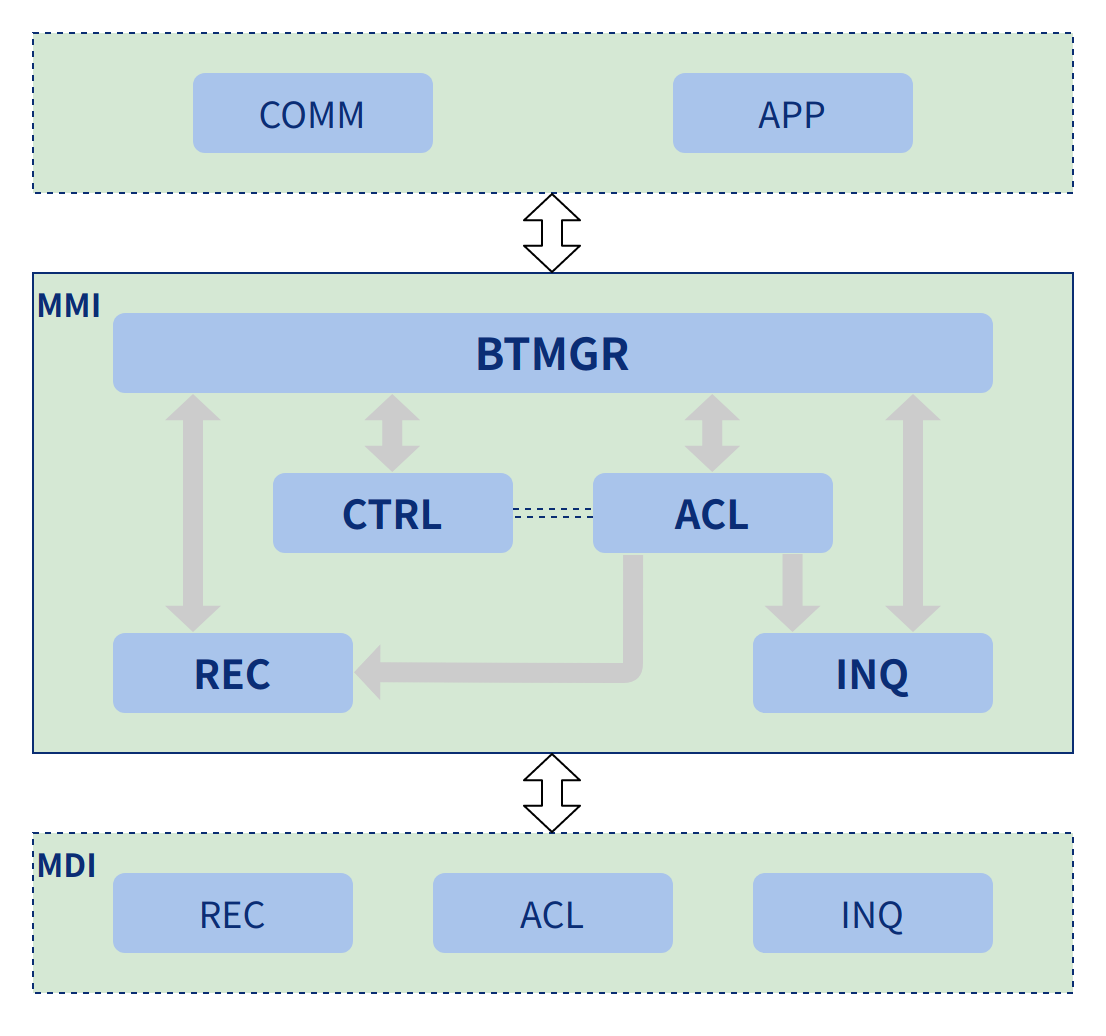
MMI, the man machine interface layer, is mainly based on business logic, the relevant functional modules on the MDI layer (explained in the following chapters) and the STK layer are processed by further integration, forming a certain function body that meets the multi-scenario and can call the configuration freely. As shown in the figure below, there are currently Audio, Phone, BT Manager, BLE Manager and other functionalities in the MMI.
- BTMGR (BT Manager) is used to manage BT discovery, connection and reconnection related operations.
- LEMGR (BLE Manager) is mainly used to manage LE broadcast and connection related operations and is still to be further developed.
- Audio is mainly used to integrate audio related modules and form a unified provisioning interface. At present, the control interfaces for music playback, alert tones, SCO and other audio are all encapsulated in this function body.
- Phone is mainly used for phone status and contacts management, and the phone number is bound to the contacts, so that when there is a phone status change, the system will automatically go to the contacts to load the contact, and will be reported to the user, together with the phone status.

BTMGR Design and Implementation
The BT Manager is an important user-oriented module that integrates the discovery, connection and reconnection functions of BT. Applications only need to call this layer of the interface to implement BT discovery, connection, disconnection and reconnection. The logical framework of this part is explained below from four perspectives: structure, status conversion, important flow and interface design.
Structure
This module provides the service management logic and external interaction access interface for BT. It consists of four main sub-modules, namely BTMGR, CTRL, ACL, REC, INQ, etc.
- The module BTMGR provides the initialization interface for each sub-module.
- The CTRL module is responsible for maintaining the control variables of the BT MGR.
- The ACL module is responsible for connection flow management.
- The REC module is mainly responsible for the management of the reconnection process.
- The INQ module is mainly responsible for the discovery process management.
Status Conversion
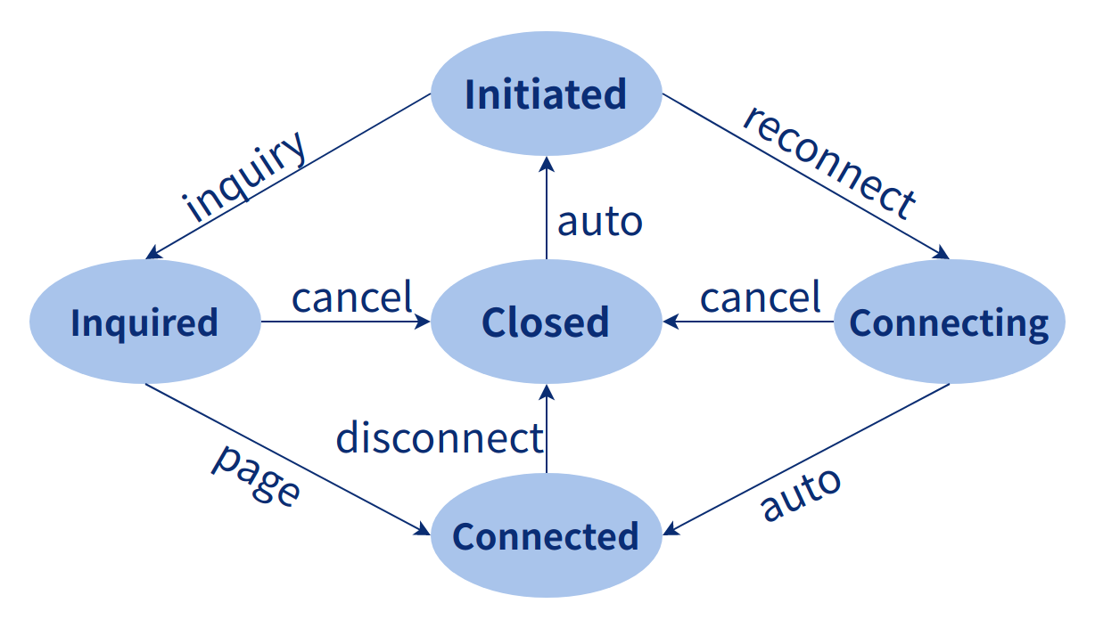
The figure below shows some of the status jump designed by BTManager in the discovery, connection and reconnection process. As you can see from the figure below, BT Manager has five states - Initiated, Requested, Closed, Connected and Connecting. The arrows point to the conversion from one state to the next and the transition between states is triggered by the actions shown on the arrows, for example, the user can initiate a page action to jump from Inquired to Connected.
Important flow
Through flowcharts and process subsequence chart we describe the relationships within and between the BT Manager modules, which work together to discover, connect, encrypt, disconnect and reconnect Bluetooth devices, as well as connecting and disconnecting profiles. The initialization process sub-sequence chart, the discovery process sub-sequence chart and the connecting process and connecting process sub-sequence chart are provided below.
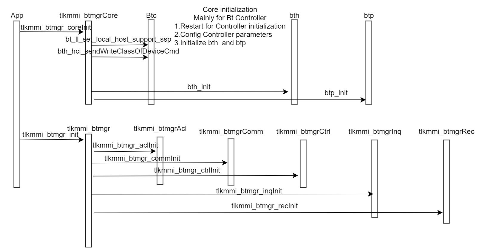
(1) Initialization flow
The figure below is a sequence chart of BT Manager initialization, which is used to assist in understanding the initialization process of BT Manager. The sequence chart consists of the following main parts: the name of the file or module; the function and its description; the calling relationship between the files and the feedback relationship. For example, the App is a module that does the initialization by calling the tlkmmi_btmgrCore function tlkmmi_btmgr_coreinit. The tlkmmi_btmgrCore file calls the bt_ll_set_local_host_support_ssp function in the Btc file to do the ssp related configuration.
(2) Discovery flow
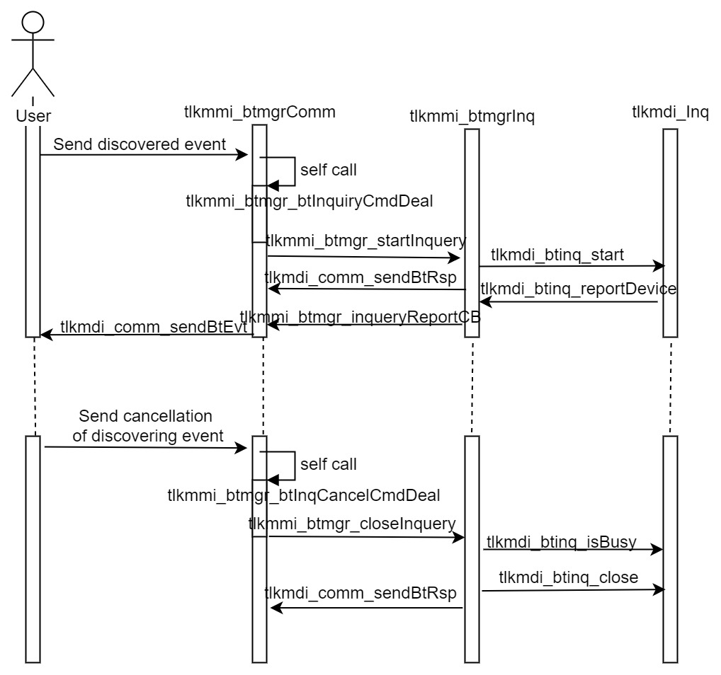
The discovery sub-flow sequence chart consists of the file name or module name, the function and the callback function. The module or file in front of it calls the module behind it through the function, or calls between functions within the file (self-call). The module that follows then returns the result or status of the execution via a callback function, for example, the tlkmmi_btmgrInq file returns the result and status of the associated execution via a callback to the tlkmmi_btmgr_inquiryReportCB function. The discovery process sub-sequence consists of two parts: the first part is the start of discovery to the reporting of the discovery results via callbacks; the second part is the cancellation of the discovery part.
(3) Connection flow
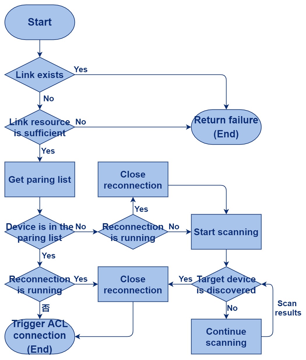
The BT connection flowchart contains three parts from a holistic point of view, one is the discovery process, the second is the connection process and the third is the reconnection process. In the flowchart below, the link is executed only if the target device exists, otherwise the discovery process needs to be initiated to find the corresponding device, and when the target device exists, it also needs to confirm whether it is currently in the reconnected state. Then the connection process can be initiated.
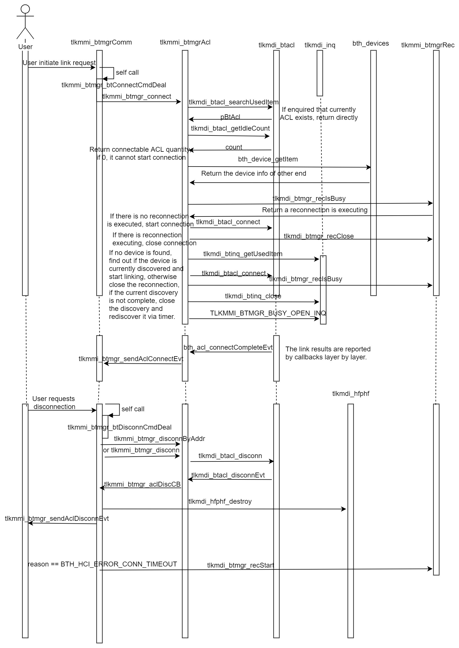
Below is the connection process subsequence chart. The connection subsequence chart also consists of the file or module name, the call relationship and the feedback relationship. The dotted lines indicate that functions in the same file are called or generate callbacks at different stages. The execution flow consists of two parts, the first part is where the user initiates the connection request and the second part is where the user initiates the disconnect request.
Interface Design
The interface design is represented by four main parts, the first part is the name of the module, the second part is the interface function of the module, the third part is the interface function definition or macro definition or data structure definition or global variable definition, etc., and the fourth part is the detailed description of the content of the third part.
(1) General Interfaces
The general interface module is mainly used to initialize the discovered and linked resources. Generally, the initialization process of the general interface will be called when the application starts, and all the sub-modules of BT Manager will be initialized.
BT Manager
Interface design
int tlkmmi_btmgr_init(void)
a) Initialize the serial port
b) Initialize the control module
c) Initialize the acl link module
d) Initialize the Inquiry module
e) Initialize reconnect module
f) Set the Bluetooth address
g) Set the local Bluetooth name
(2) COMM Interface
This module is mainly used to manage the serial communication, getting messages from the serial port of the MDI layer, and the results or responses generated by the execution will be encapsulated by the MMI layer and sent to the MDI layer, which will send them to the application or other modules. It is mainly used to handle discovery and link commands from applications and to return their results.
Bt Manager Comm design
Interface definition:
Register callback functions for serial port signal processing:
int tlkmmi_btmgr_commInit(void)
Convert Profile types to Channel types:
uint08 tlkmmi_btmgr_ptypeToCtype(uint08 ptype, uint08 usrID)
Send ACL connection message via the serial port:
void tlkmmi_btmgr_sendAclConnectEvt(uint16 handle, uint08 status, uint08 *pBtAddr)
Send ACL disconnection messages via the serial port:
void tlkmmi_btmgr_sendAclDisconnEvt(uint16 handle, uint08 reason, uint08 *pBtAddr)
Send connection message for Profile via serial port:
void tlkmmi_btmgr_sendProfConnectEvt(uint16 handle, uint08 status, uint08 ptype, uint08 usrID, uint08 *pBtAddr)
Send Profile's disconnect message via the serial port:
void tlkmmi_btmgr_sendProfDisconnEvt(uint16 handle, uint08 reason, uint08 ptype, uint08 usrID, uint08 *pBtAddr)
(3) CTRL Interface
It is mainly used to initialize control variables and to query the Bluetooth name and Bluetooth address to assist in the normal use of other modules.
BT Manager Ctrl design
Data structure:
Define the data structure of BT Ctrl:
typedef struct{
        uint08 btaddr[6];
        uint08 btname[TLKMMI_BTMGR_BTNAME_LENS];
}tlkmmi_btmgr_ctrl_t;
- btaddr: Bluetooth address
- btname: Bluetooth name
Define gTlkMmiBtmgrCtrl:
tlkmmi_btmgr_ctrl_t gTlkMmiBtmgrCtrl;
Interface definition:
Initialize gTlkMmiBtmgrCtrl; Read Bluetooth address and name from flash.
int tlkmmi_btmgr_ctrlInit(void)
Get the device name:
uint08 *tlkmmi_btmgr_getBtName(void)
Get Bluetooth address:
uint08 *tlkmmi_btmgr_getBtAddr(void)
(4) ACL Interface
The ACL interface defines the data structure and interface functions, as well as a detailed description of the individual basic elements of the data structure and interface definition. Its main functions are the connecting and disconnecting of ACLs; the linking and disconnecting of individual Profiles; and how to use the discovery and reconnection functions under the various scenarios.
BTManager ACL design
Macro definition:
Define the Timeout value of the scheduling timer:
#define TLKMMI_BTMGR_TIMEOUT 200000
Define the timeout value of the connection:
#define TLKMMI_BTMGR_TIMEOUT_MS 200
Wait duration timeout value:
#define TLKMMI_BTMGR_WAIT_TIMEOUT (5000000/TLKMMI_BTMGR_TIMEOUT)
RSSI threshold for discovery devices:
#define TLKMMI_BTMGR_INQ_RSSI 0x9C
Data structure:
typedef enum{
   TLKMMI_BTMGR_BUSY_NONE = 0x00,
   TLKMMI_BTMGR_BUSY_WAIT_REC  = 0x01,
   TLKMMI_BTMGR_BUSY_WAIT_INQ  = 0x02,
   TLKMMI_BTMGR_BUSY_OPEN_INQ  = 0x04,                   TLKMMI_BTMGR_BUSY_WAIT_DEV  = 0x08,
   TLKMMI_BTMGR_BUSY_OPEN_CONN = 0x10,
   TLKMMI_BTMGR_BUSY_WAIT_CONN = 0x20,
}TLKMMI_BTMGR_BUSY_ENUM;
- TLKMMI_BTMGR_BUSY_WAIT_REC mark whether the current wait for reconnection is repeated.
- TLKMMI_BTMGR_BUSY_WAIT_INQ mart whether currently wait for Inquiry again.
- TLKMMI_BTMGR_BUSY_OPEN_INQ mark whether currently reopen Inquiry.
- TLKMMI_BTMGR_BUSY_WAIT_DEV mark whether currently wait for device again.
- TLKMMI_BTMGR_BUSY_OPEN_CONN mark whether initiate the connection.
- TLKMMI_BTMGR_BUSY_WAIT_CONN mark whether currently it is needed to wait for the reconnection.
typedef struct{
        uint08 busys;
        uint08 flags;
        uint16 timeout;
        uint32 devClass;
        uint16 connTime;
        uint08 btaddr[6];
        tlkapi_timer_t timer;
}tlkmmi_btmgr_acl_t;
- busys: stores whether the current execution needs to be resent (pending flag)
- flags:determine if the currently received Event is feedback for the currently executed action (determine filter conditions)
- timeout: set the timeout for the currently executed action
- devClass: device class of the other party
- connTime: connection time
- btaddr: the Bluetooth address of the other party
- timer:timer for action execution
Interface definition:
a) Initialize the data structure of BT ACL
b) Initialize timer
c) Register callback function
int tlkmmi_btmgr_aclInit(void)
Check if acl link is currently available:
bool tlkmmi_btmgr_aclIsBusy(void)
Register the callback function of ACL connection:
void tlkmdi_btmgr_regAclConnectCB(TlkMmiBtMgrAclConnectCallback connCB)
Register the callback function for ACL disconnection:
void tlkmdi_btmgr_regAclDisconnCB(TlkMmiBtMgrAclDisconnCallback discCB)
Register the callback function for Profile connection:
void tlkmdi_btmgr_regProfileConnectCB(TlkMmiBtMgrProfileConnectCallback connCB)
Register the callback function for Profile disconnection:
void tlkmdi_btmgr_regProfileDisconnCB(TlkMmiBtMgrProfileDisconnCallback discCB)
Initiate a device connection to the target address:
int tlkmmi_btmgr_connect(uint08 btaddr[6], uint16 timeout)
Disconnect the ACL specified by handle:
int tlkmmi_btmgr_disconn(uint16 handle)
Disconnect the ACL specified by the Bluetooth address:
int tlkmmi_btmgr_disconnByAddr(uint08 btaddr[6])
(5) INQ Interface
It is mainly used to describe the interface design in device discovery and the detailed description of the interface design elements. Its function is mainly to provide the user with discovery functions in various different usage scenarios.
BT Manager Inquiry design
Interface design:
Inquiry initialization:
int tlkmmi_btmgr_inqInit(void)
Start Inquiry, and the interface can be specified:
int tlkmmi_btmgr_startInquery(uint08 inqType, uint08 rssiThd, uint08 maxNumb, uint16 timeout, bool isGetName)
- inqType: Inquiry type.
- rssiThd: rssi threshold
- maxNmb: maximum number of devices to be reported
- timeout: Inquiry time
- isGetName:whether get the device name.
Close Inquiry.
int tlkmmi_btmgr_closeInquery(void)
(6) REC Interface
The main purpose is to describe the interface design and the detailed description of the interface design elements in device reconnection. The main function is to provide the user with the ability to connect back in different usage scenarios.
BT Manager Reconnect design
Interface design:
int tlkmmi_btmgr_recInit(void)
a) Initialization re-connection
b) Set Inquiry+page mode
c) Set Scan and Page
d) Enable page and scan
e) Register the callback function.
Restart:
int tlkmdi_btmgr_recStart(uint08 *pDevAddr, uint32 devClass)
a. pDevAddr: device address of the other party.
b. device type
Close the reconnection:
int tlkmdi_btmgr_recClose(void)
Query reconnection in progress:
bool tlkmdi_btmgr_recIsBusy(void)
Query whether the page is being executed:
bool tlkmmi_btmgr_recIsPage(void);
Query whether a scan (page scan or inquiry scan) is being executed:
bool tlkmmi_btmgr_recIsScan(void);
Query the device address in the execution page:
uint08 *tlkmmi_btmgr_recPageAddr(void);
LEMGR Design and Implementation
TBD
Audio Design and Implementation
The Audio module is used to manage each Audio business requirement of the application, to make appropriate strategies for the execution of these requirements, and to control the updating of the volume and Audio information and status for each usage scenario. At the same time, it controls the MDI layer to execute each Audio task and monitors the status of MDI execution. It is a good separation of policy and execution, which facilitates rapid application development and maintenance. The module consists of four main parts: the first part is the structure; the second part is the status conversion; the third part is the important flow; and the fourth part is the interface design.
Structure
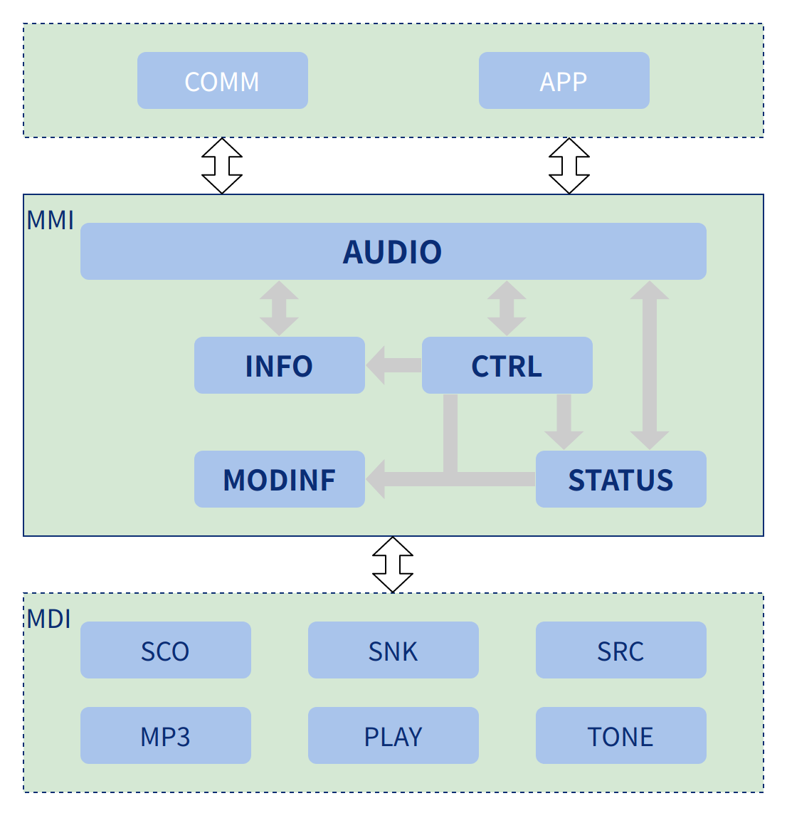
As defined by Audio's functional requirements, the Audio structure includes the AUDIO, INFO, CTRL, MODINF and STATUS modules. The functions of their sub-modules are shown below.
- AUDIO: provides an access interface to Audio.
- INFO: the user needs to perform information access, such as volume, playback progress, or information updates.
- CTRL: Audio needs to cater for a variety of different scenarios of play, stop, etc..
- MODINF: this module is mainly used to unify the behavior of the various Audio operations and is easily extensible.
- STATUS: Manage the priority and execution behavior of Audio when it comes to different user actions.
Status Conversion
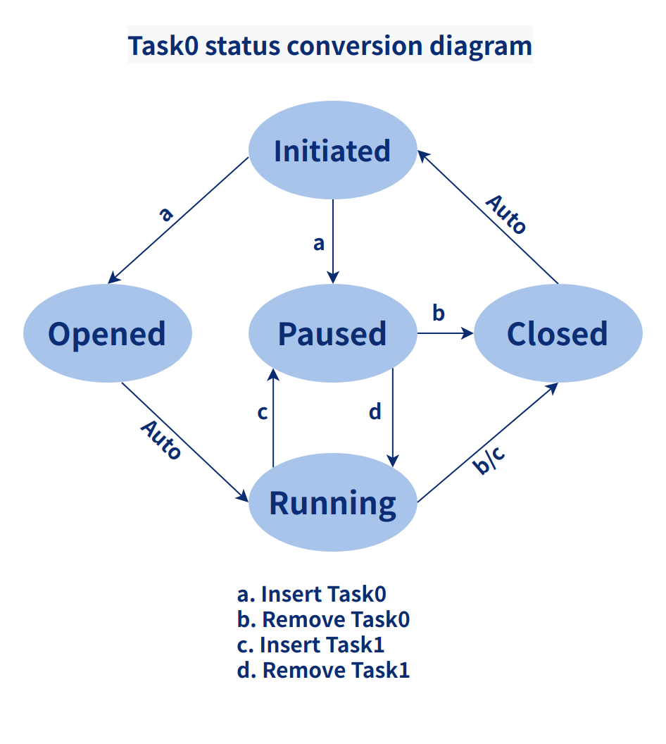
The Audio status conversion consists of five status: Initiated, Opened, Closed, Running and Paused. The conversion path between states is shown by the single arrow below, with the arrow pointing to the next state. Conversions between states are performed by the execution actions of a,b,c,d, and Auto. The essence of this is that the next execution behavior of the tasks in the current task queue in each state needs to be handled. For example, if the local tone is in the Running state (ringing) and a voice call task is inserted that needs to be executed immediately, but the local tone has not yet finished executing, but there is no need for it to continue after the call has ended, so the local tone can be paused and removed from the task queue and the voice call task can be started.
Important Flow
The Audio process is divided into three sections based on the execution of Audio, each of which is controlled by a different Audio operation behavior: the Add Task process, the Remove Task process and the Task Execution process.
(1) Add Task
Whenever a new task needs to be executed, the new task needs to be inserted into Audio's work queue in order of priority. If the task is to be executed immediately, it needs to be inserted at the top of the task queue and executed immediately; or if it is to be inserted by a high priority task, the priority of the currently executing task and the task to be inserted need to be compared to find the correct position for insertion.The tasks in the Audio queue are executed in order.
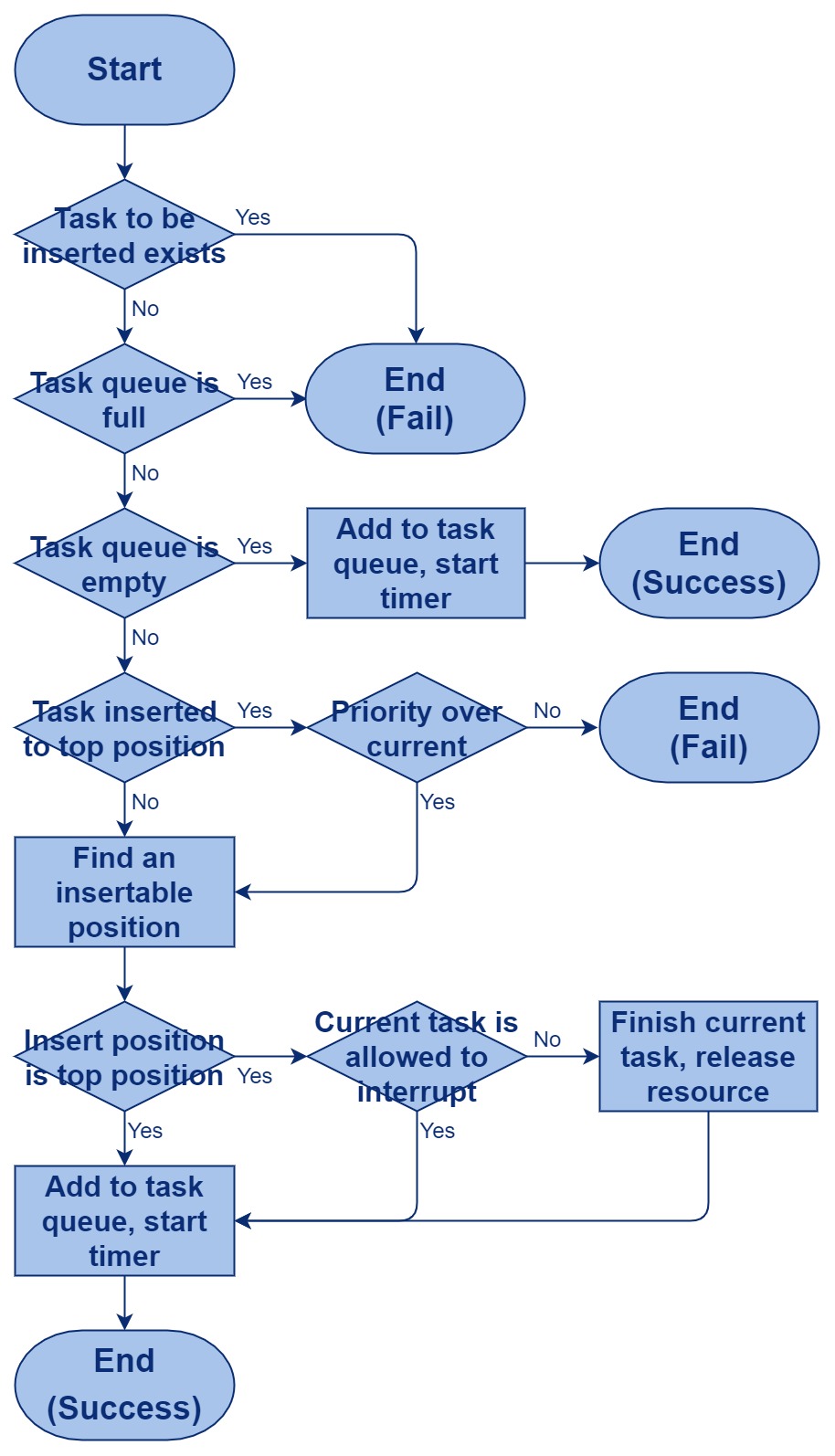
(2) Delete Task
Deleting a task means removing from the task queue a task that has finished executing or that cannot be executed properly for other reasons. Tasks at the top of this queue are guaranteed to execute smoothly.
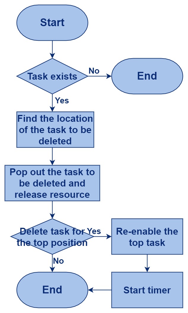
(3) Execute Task
The flow of task execution is complex, with two main Timers controlling the current task execution. The first Timer runs the Audio task and mainly manages the scheduling of the task. The second Timer manages the execution of the data when the task is executed, and adjusts the time interval for the execution of the task according to the success or otherwise of the task execution.
The following shows the sub-sequences of each process.
a.Initialization flowchart:
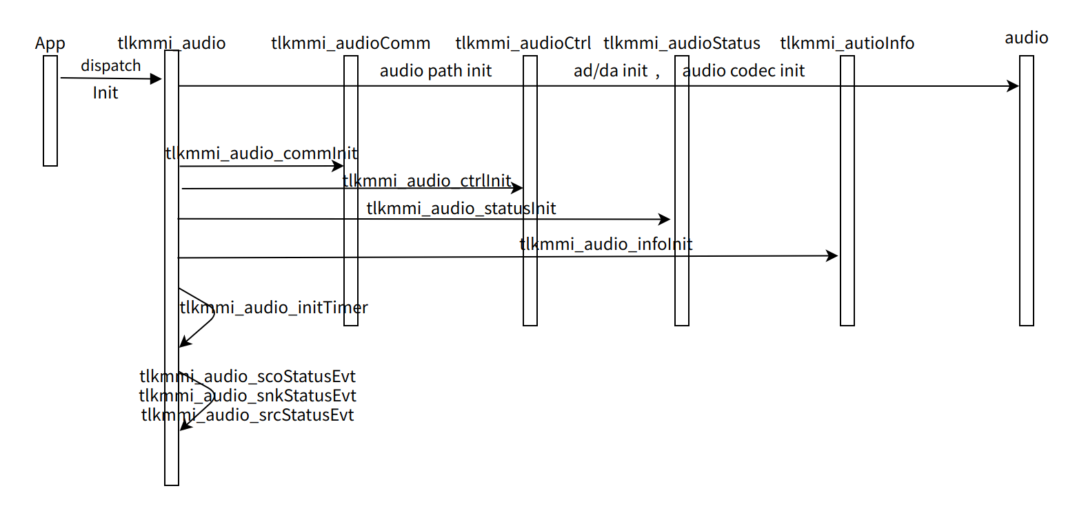
Detailed program execution can be found in the individual function interface design of each module.
b.deinit flowchart

c.Play Start flowchart

d.Play stop flowchart
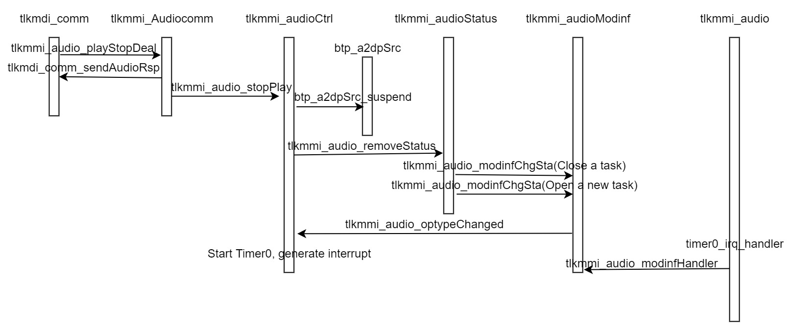
The Play next and Play prev processes are similar to the Play execution process above, please refer to the description above.
e.Inquire Audio status
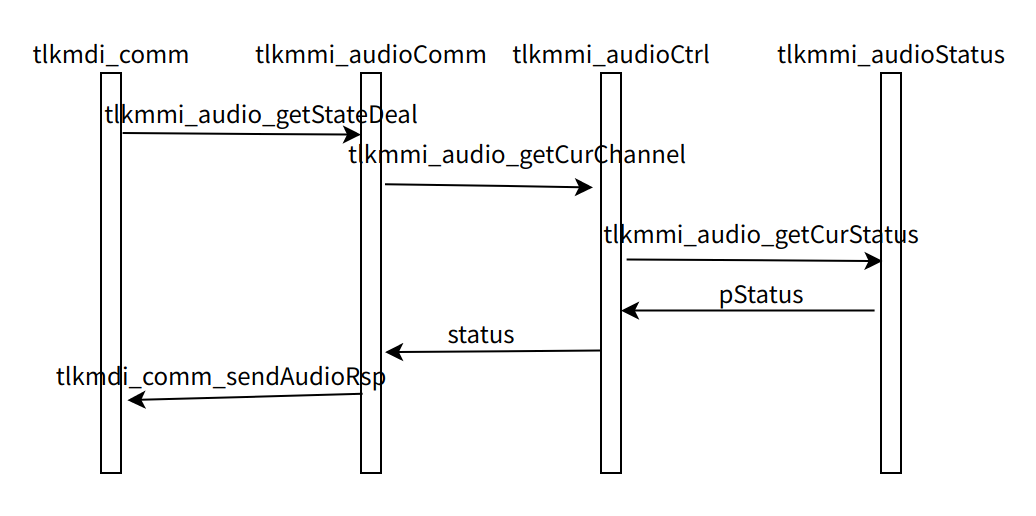
Query progress function, Query play duration function, Query song name function, Query artist function, Query play mode function, Set play mode function, are similar to the Query Audio status function, and can be referred to it.
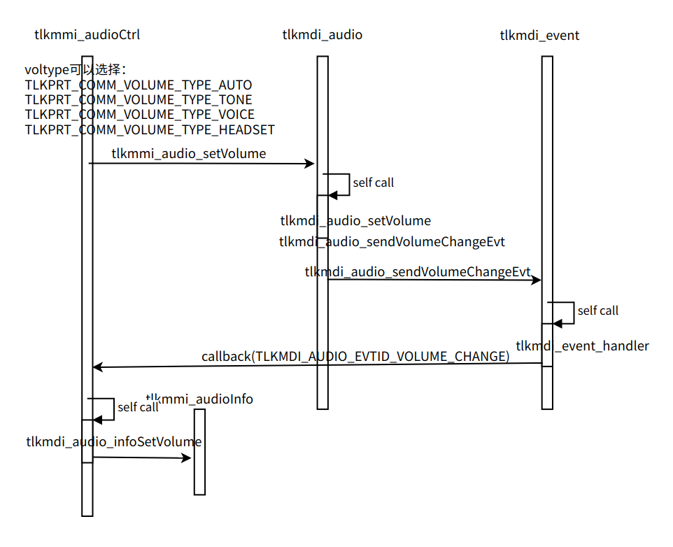
f.Inquire audio volume
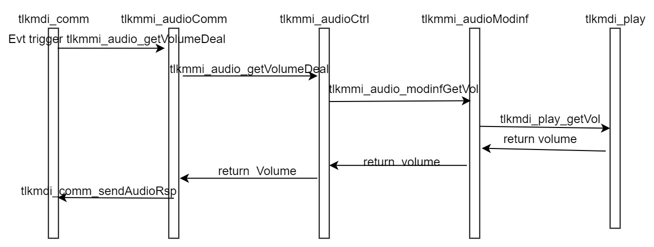
Setting the volume function and adjusting the volume function is similar to the above process, you can refer to the above process.
g.Set Audio Info
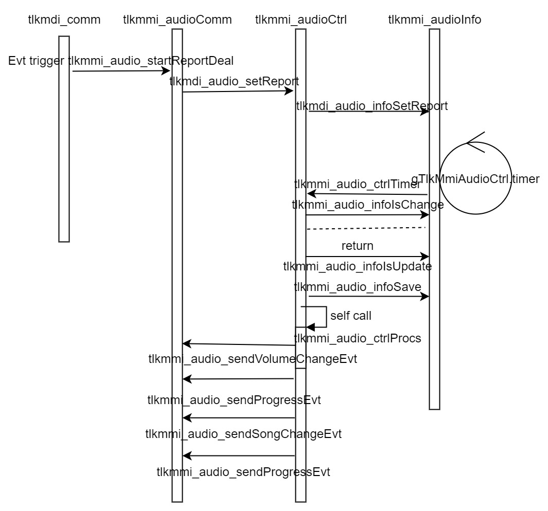
The cancellation of the Audio message reporting function is similar to the above process, which can be found above.
Interface Design
(1) Audio Interface Design
It is primarily used to describe the design of the data structures and interfaces in Audio and the detailed description of the elements within them. Its function is mainly to give the application access to the entire Audio module, including initializing and destroying Audio's resources, adding the current Audio task to Audio's policy management array, or removing a task from it.
Audio Interface design
Macro definition:
Define the Timeout for Audio task scheduling:
#define TLKMMI_AUDIO_TIMEOUT 100000
Define the Timeout for Audio status update:
#define TLKMMI_AUDIO_TIMEOUT_MS 100
Define the Time out for Audio sub-task:
#define TLKMMI_AUDIO_TIMER_TIMEOUT (3000000/TLKMMI_AUDIO_TIMEOUT) //Prevent timer termination, which may cause problem
Define the Timeout for Audio information update:
#define TLKMMI_AUDIO_INFO_TIMEOUT (5000000/TLKMMI_AUDIO_TIMEOUT)
Define the DBG switch for the Audio module:
#define TLKMMI_AUDIO_DBG_FLAG (TLKMMI_AUDIO_DBG_ENABLE | TLKAPI_DBG_FLAG_ALL)
Define the DBG sign for the Audio module:
#define TLKMMI_AUDIO_DBG_SIGN "[MMI]"
Data structure:
typedef enum{
  TLKMMI_AUDIO_OPTYPE_NONE = 0,
  TLKMMI_AUDIO_OPTYPE_TONE,
  TLKMMI_AUDIO_OPTYPE_PLAY,
  TLKMMI_AUDIO_OPTYPE_HF,
  TLKMMI_AUDIO_OPTYPE_AG,
  TLKMMI_AUDIO_OPTYPE_SCO,
  TLKMMI_AUDIO_OPTYPE_SRC,
  TLKMMI_AUDIO_OPTYPE_SNK,
  TLKMMI_AUDIO_OPTYPE_MAX,
 } TLKMMI_AUDIO_OPTYPE_ENUM;
- TLKMMI_AUDIO_OPTYPE_TONE: play local tone.
- TLKMMI_AUDIO_OPTYPE_PLAY: play local music.
- TLKMMI_AUDIO_OPTYPE_HF: HF actively initiate connecting phone.
- TLKMMI_AUDIO_OPTYPE_AG: AG actively initiate connecting headphone.
- TLKMMI_AUDIO_OPTYPE_SCO: Controls the individual states of the SCO link establishment, mainly used in voice recognition and telephony.
- TLKMMI_AUDIO_OPTYPE_SRC: Connects headphones and sends music data to them.
- TLKMMI_AUDIO_OPTYPE_SNK: Connects to the phone and receives music data from the phone.
Interface definition:
This interface has the following functions:
int tlkmmi_audio_init(void);
a) Initialization of Audio Path including Gain setting, Codec initialization, Codec's AD module initialization, sampling frequency setting
audio_set_codec_in_path_a_d_gain(CODEC_IN_D_GAIN_0_DB, CODEC_IN_A_GAIN_8_DB);
audio_set_codec_out_path_a_d_gain(CODEC_OUT_D_GAIN_0_DB,CODEC_OUT_A_GAIN_0_DB);
tlkdev_codec_init(TLKDEV_CODEC_MODE_SINGLE, TLKDEV_CODEC_SELC_INNER);
tlkdev_codec_setSampleRate(44100);
audio_set_codec_adc_wnf(CODEC_ADC_WNF_INACTIVE);
audio_codec_adc_enable(0);
b) Initialize the other modules of audio
tlkmmi_audio_infoInit(); AudioInfo initialization
tlkmmi_audio_commInit(); Audio serial communication module initialization
tlkmmi_audio_ctrlInit(); Audio control module initialization
tlkmmi_audio_statusInit(); Audio status control initialization
c) Timer initialization
tlkmmi_adapt_initTimer(&gTlkMmiAudioCurTimer, tlkmmi_audio_timer, nullptr, TLKMMI_AUDIO_TIMEOUT); Initialize the AudioTimer event controller.
tlkmmi_audio_initTimer(); set AudioTimer interrupt.
d) Register callback function
tlkmdi_sco_regStatusFunc(tlkmmi_audio_scoStatusEvt); Register SCO status event callback.
btp_event_regCB(BTP_EVTID_A2DPSNK_STATUS_CHANGED, tlkmmi_audio_snkStatusEvt); Register audio snk status event callback.
Query if there is an Audio action property currently being executed:
bool tlkmmi_audio_isBusy(void);
Destroy the resources controlled by the Audio state represented by the Handle.
void tlkmmi_audio_destroy(uint16 handle);
Insert the current Audio operation into the Audio state management array:
extern int tlkmmi_audio_insertStatus(uint16 aclHandle, uint08 optype);
Remove the current Audio operation from the Audio state management array:
extern int tlkmmi_audio_removeStatus(uint16 aclHandle, uint08 optype);
Query the current local playback status:
extern bool tlkmmi_audio_isLocalPlay(void);
Stop the current local playback:
extern void tlkmmi_audio_stopLocalPlay(void);
Audio global variables:
 tlkapi_timer_t gTlkMmiAudioCurTimer;
 uint08 gTlkMmiAudioTmrCount = 0;
 uint08 gTlkMmiAudioTmrState = 0;
 uint08 gTlkMmiAudioCurOptype
 uint16 gTlkMmiAudioCurHandle;
- gTlkMmiAudioCurTimer:Timer1 control list
- gTlkMmiAudioTmrCount: Mark how many timer-1 have been used in total, to detect if a timer-1 event has not been executed.
- gTlkMmiAudioTmrState: Mark the status of Timer-1, 0 - for Idle status, 2 - for Running status.
- gTlkMmiAudioCurOptype: The current execution of Audio behavior.
- gTlkMmiAudioCurHandle: The current handle of the execution.
void timer0_irq_handler(void)
a) tlkmmi_audio_modinfHandler(gTlkMmiAudioCurOptype) interrupt handler will start the Handler that is currently executing the action, handling the next actions such as Stream Audio data, etc.
b) Restart a Timer0 to trigger the Timer0 interrupt.
(2) Audio Serial Communication Module Design
It is mainly used to describe the interface design in device discovery and the detailed description of the interface design elements. Its function is mainly to provide the user with discovery functionality in various different usage scenarios. The serial port is the bridge between receiving and sending data from the application and the MMI. Audio Comm is able to drive different modules from the user's request through the serial port and at the same time can send the result of the execution back to the application.
AudioComm
External interface
Used to register callbacks related to the handling of Audio Channel events:
int tlkmmi_audio_commInit(void)
(3) Audio Ctrl Design
The main purpose is to describe the data structure and interface design in Audio Control and the detailed description of the interface design elements. It defines interfaces for local playback, tone, calls to A2DP Source and A2DP Sink and interfaces for volume music status queries, plus callback functions to monitor the status reported by the underlying profile, etc.
Audio Ctrl design
Macro definition:
Define the volume step for Tone:
#define TLKMMI_AUDIO_VOLUME_TONE_STEP 5
Define the volume step for Music:
#define TLKMMI_AUDIO_VOLUME_MUSIC_STEP 3
Define the volume step for Voice:
#define TLKMMI_AUDIO_VOLUME_VOICE_STEP 6
Define the volume step for Headset:
#define TLKMMI_AUDIO_VOLUME_HEADSET_STEP 6
Data structure:
typedef enum{
        TLKMMI_AUDIO_REPORT_BUSY_NONE     = 0x0000,
        TLKMMI_AUDIO_REPORT_BUSY_PROGR100 = 0x0001,
        TLKMMI_AUDIO_REPORT_BUSY_PROGR000 = 0x0002,
        TLKMMI_AUDIO_REPORT_BUSY_PROGRESS = 0x0004,
     TLKMMI_AUDIO_REPORT_BUSY_SONG_CHANGE   = 0x0800,
        TLKMMI_AUDIO_REPORT_BUSY_STATE_CHANGE = 0x0010,
      TLKMMI_AUDIO_REPORT_BUSY_VOLUME_CHANGE = 0x0020,
}TLKMMI_AUDIO_REPORT_BUSYS_ENUM;
TLKMMI_AUDIO_REPORT_BUSY_PROGR100
TLKMMI_AUDIO_REPORT_BUSY_PROGR000
TLKMMI_AUDIO_REPORT_BUSY_PROGRESS
music progress report events.
TLKMMI_AUDIO_REPORT_BUSY_SONG_CHANGE: Used to mark events for musical changes
TLKMMI_AUDIO_REPORT_BUSY_STATE_CHANGE: mark play status change.
TLKMMI_AUDIO_REPORT_BUSY_VOLUME_CHANGE: play volume change.
typedef struct{
        uint08 rptEn;
        uint08 resv0;
        uint16 busys;
        uint16 timeout;
        uint16 interval;
        uint16 oldIndex;
        uint16 newIndex;
        uint08 oldOptype;
        uint08 newOptype;
        uint08 volValue;
        uint08 volChannel;
}tlkmmi_audio_report_t;
- uint08 rptEn: indicates whether repeat
- uint08 resv0: reserved
- uint16 busys: used to set the current unexecuted action, and use with timer.
- uint16 timeout: the timeout of the timer
- uint16 interval: report interval
- uint16 oldIndex: the old music index
- uint16 newIndex: the new music index
- uint08 oldOptype: old Action type
- uint08 newOptype: new Action type
- uint08 volValue: old volume value
- uint08 volChannel: new volume value, this data structure is mainly used to report the above information.
typedef struct{
        uint16 mp3Timeout;
        uint16 mp3Interval;
}tlkmmi_audio_update_t;
- mp3Timeout: the timeout time of the mp3
- mp3Interval: the time interval of the mp3, this data structure is used to update the above timeout and time interval.
typedef struct{
        tlkapi_timer_t timer;
        tlkmmi_audio_report_t report;
}tlkmmi_audio_ctrl_t;
- timer: used to control the execution of each event of the report.
- report: the report event to be executed, used to control the individual events of the report.
tlkmmi_audio_ctrl_t gTlkMmiAudioCtrl;
gTlkMmiAudioCtrl: Audio control block
External interface:
int tlkmmi_audio_ctrlInit(void);
a) Initialize the Audio control block
b) Register Audio related callback functions
c) Initialize Audio control-related timers
d) Set initial volume for each Audio operation
e) Initialize report-related data
bool tlkmmi_audio_startPlay(uint16 fileIndex);
a) Execute A2dp's start process
b) Set the index for playing music
c) Add the play task to the Audio task state control array
void tlkmmi_audio_stopPlay(void);
a) suspend A2dp
b) Remove music playback from the Audio task control array
c) Retain audio information
Determine if it is local play:
bool tlkmmi_audio_isLocalPlay(void);
Stop local play:
void tlkmmi_audio_stopLocalPlay(void);
Play next:
bool tlkmmi_audio_playNext(void);
a) Toggle information for playing the next song
b) Add the playback task to the Audio task status control
Play the previous song:
bool tlkmmi_audio_playPrev(void);
a) Toggle the information for playing the previous song
b) Add the play task to the Audio task status control.
Play Tones:
bool tlkmmi_audio_startTone(uint16 fileIndex, uint16 playCount);
a) Set the tone related parameters
b) Add the play task to the Audio task status control.
Stop playing the Tone sound and add the play task to the Audio task status control:
void tlkmmi_audio_stopTone(void);
Turn up the volume, the input parameter is Channel, which is used to find the current Action performed by Audio:
bool tlkmmi_audio_volumeInc(uint08 channel);
Turn down the volume:
bool tlkmmi_audio_volumeDec(uint08 channel);
Get the volume of the Audio action corresponding to the specified channel:
int tlkmmi_audio_getVolume(uint08 channel, uint08 *pVolume);
Set the volume (Audio action corresponding to the channel):
bool tlkmmi_audio_setVolume(uint08 channel, uint08 volume, bool isStep, bool isDec);
Enable local play music information reporting:
int tlkmdi_audio_setReport(uint08 enable, uint16 interval);
Get the current Channel:
int tlkmmi_audio_getCurChannel(uint08 *pChannel);
Get the operation type of Audio by Channel:
int tlkmmi_audio_channelToOptype(uint08 channel, uint08 *pOptype);
Find a Channel by Audio's operation type:
int tlkmmi_audio_optypeToChannel(uint08 optype, uint08 *pChannel);
Switch between old and new Audio tasks:
void tlkmmi_audio_optypeChanged(uint08 newOptype, uint16 newHandle, uint08 oldOptype, uint16 oldHandle);
(4) Audio Info Design
It is used to describe the data structure and interface design in Audio Info and the detailed description of the interface design elements. It is used to manage the reporting of Audio Info updates, manage volume changes and Audio playback status. It also manages the storage and loading of Audio Info.
Audio Info design
Macro definition:
Define the sign for Audio volum storage:
#define TLKMDI_AUDIO_VOLUME_SAVE_SIGN 0x3A
Define the version for Audio volume storage:
#define TLKMDI_AUDIO_VOLUME_SAVE_VERS 0x02
Define the address for Audio volume storage:
#define TLKMDI_AUDIO_VOLUME_SAVE_ADDR TLK_CFG_FLASH_VOLUME_ADDR
Define Audio valume save size:
#define TLKMDI_AUDIO_VOLUME_SAVE_SIZE 12
Data structure:
typedef struct{
        uint08 src;
        uint08 snk;
        uint08 sco;
        uint08 play;
        uint08 tone;
        uint08 hfpHF;
        uint08 hfpAG;
        uint08 resv0;
        uint08 resv1;
        uint08 enReport;
        uint16 interval;
        uint08 resv002[4];
}tlkmmi_audio_infoItem_t;
- src: mark A2DP src volume
- snk: mark A2DP sink volume
- sco: mark SCO volume
- play: mark play volume
- tone: mark tone volume
- hfpHF: mark HF volume
- hfpAG: mark AG volume
- resv0:reserved
- resv1:reserved
- enReport: enable audio info report
- interval: report interval
typedef struct{
        uint08 isChange;
        uint08 reserved;
        uint16 interval;
        tlkapi_save_ctrl_t save;
        tlkmmi_audio_infoItem_t item;
}tlkmmi_audio_infoCtrl_t;
- isChange: mark whether the audio info has changed
- interval: event reporting interval
- save: the stored information header
- item: collection of information
Used to indicate whether information needs to be stored or updated or found and retrieved
gTlkMmiAudioInfoCtrl;
Used to control Audio information.
Interface definition:
Initialize Audio control information:
int tlkmmi_audio_infoInit(void)
Check if the information has changed:
bool tlkmmi_audio_infoIsChange(void)
Check if information needs to be updated:
bool tlkmmi_audio_infoIsUpdate(void)
Load information:
int tlkmmi_audio_infoLoad(void)
Save information:
int tlkmmi_audio_infoSave(void)
Get the volume of the current Audio execution task:
int tlkmdi_audio_infoGetVolume(uint08 optype, uint08 *pVolume)
Get the reporting conditions:
int tlkmdi_audio_infoGetReport(uint08 *pEnable, uint16 *pInterval)
Store the volume of the current Audio task:
int tlkmdi_audio_infoSetVolume(uint08 optype, uint08 volume)
Set the reporting conditions:
int tlkmdi_audio_infoSetReport(uint08 enable, uint16 interval)
(5) Audio Modinf Design
Mainly used to describe the data structure and interface design in Audio ModInf and to detail the design elements, this Module Definition defines the interfaces used to access the various tasks of Audio, facilitating the management of different function calls, including start, end, switch states, interrupt handling, etc.
Audio Modinf design
Data structure:
It defines the function interface, which consists of:
typedef struct{
 int (*Start)(uint16 handle, uint32 param);
 int (*Close)(uint16 handle);
 bool(*ToNext)(void);
 bool(*ToPrev)(void);
 bool(*Switch)(uint16 handle, uint08 status);
 bool(*IsBusy)(void);
 uint(*Intval)(void);
 bool(*IrqProc)(void);
}tlkmmi_audio_modinf_t;
- Start: interface to start an action
- Close: interface to end an action
- ToNExt: next action
- ToPrev: previous action
- Switch: interface to the status conversion function
- isBusy: query if there is an action being executed or not
- Intval: interface to the duration interval function
- IrqProc: interface to the event handling function
Interface definition:
Start the current Audio execution:
int tlkmmi_audio_modinfStart(TLKMMI_AUDIO_OPTYPE_ENUM optype, uint16 handle, uint32 param)
End the current Audio execution action:
int tlkmmi_audio_modinfClose(TLKMMI_AUDIO_OPTYPE_ENUM optype, uint16 handle)
Audio task execution handler:
void tlkmmi_audio_modinfTimer(TLKMMI_AUDIO_OPTYPE_ENUM optype)
Start the next track of Audio:
bool tlkmmi_audio_modinfToNext(TLKMMI_AUDIO_OPTYPE_ENUM optype)
Start Audio's previous track:
bool tlkmmi_audio_modinfToPrev(TLKMMI_AUDIO_OPTYPE_ENUM optype)
Query whether the current Audio operation is in Running status:
bool tlkmmi_audio_modinfIsBusy(TLKMMI_AUDIO_OPTYPE_ENUM optype)
Get the Interval of the current Audio operation:
uint tlkmmi_audio_modinfIntval(TLKMMI_AUDIO_OPTYPE_ENUM optype)
Audio status conversion function:
bool tlkmmi_audio_modinfSwitch(TLKMMI_AUDIO_OPTYPE_ENUM optype, uint16 handle, uint08 status)
Audio execution handler function:
Bool tlkmmi_audio_modinfIrqProc(TLKMMI_AUDIO_OPTYPE_ENUM optype)
Query the properties of the current Audio execution behavior:
const tlkmmi_audio_modinf_t *tlkmmi_audio_getModinf(TLKMMI_AUDIO_OPTYPE_ENUM optype)
(6) Audio task control strategy module design
Mainly used to describe the data structure and interface design in Audio Status and the detailed description of the interface design elements, this module is mainly used to design the execution strategy for each different Audio task between task queues, such as where in the queue the current Audio task is inserted, the position determines whether the current task is executed immediately or deferred, or what strategy is used to initiate the execution of the task.
Audio Status Design
Macro definition
The maximum number of tasks in Audio's queue:
#define TLKMMI_AUDIO_STATUS_ITEM_NUMB 4
Define invalid Audio handle:
#define TLK_INVALID_HANDLE 0xFFFF
Data structure:
typedef enum{
 TLKMMI_AUDIO_PRIORITY_LEVEL0 = 0,
 TLKMMI_AUDIO_PRIORITY_LEVEL1,
 TLKMMI_AUDIO_PRIORITY_LEVEL2,
 TLKMMI_AUDIO_PRIORITY_LEVEL3,
 TLKMMI_AUDIO_PRIORITY_LEVEL4,
 TLKMMI_AUDIO_PRIORITY_LEVEL5,
 TLKMMI_AUDIO_PRIORITY_LEVEL6,
 TLKMMI_AUDIO_PRIORITY_LOWEST = TLKMMI_AUDIO_PRIORITY_LEVEL0,
TLKMMI_AUDIO_SCO_PRIORITY = TLKMMI_AUDIO_PRIORITY_LEVEL6,
TLKMMI_AUDIO_HFP_PRIORITY  = TLKMMI_AUDIO_PRIORITY_LEVEL4,
TLKMMI_AUDIO_SRC_PRIORITY = TLKMMI_AUDIO_PRIORITY_LEVEL2,
TLKMMI_AUDIO_SNK_PRIORITY  = TLKMMI_AUDIO_PRIORITY_LEVEL1,
TLKMMI_AUDIO_TONE_PRIORITY = TLKMMI_AUDIO_PRIORITY_LEVEL5,
TLKMMI_AUDIO_PLAY_PRIORITY = TLKMMI_AUDIO_PRIORITY_LEVEL0,
}TLKMMI_AUDIO_PRIORITY_ENUM;
Define the priority of event processing, as follows, in descending order of operational priority.
TLKMMI_AUDIO_SCO_PRIORITY
TLKMMI_AUDIO_HFP_PRIORITY
TLKMMI_AUDIO_SRC_PRIORITY
TLKMMI_AUDIO_SNK_PRIORITY
TLKMMI_AUDIO_TONE_PRIORITY
TLKMMI_AUDIO_PLAY_PRIORITY
typedef struct{
        uint08 optype;
        uint08 priority;
        uint08 isMutex;
        uint08 isFirst;
}tlkmmi_audio_statusFunc_t;
- optype: define the Audio task type, refer to TLKMMI_AUDIO_OPTYPE_ENUM for the specific type.
- priority: the priority of the Audio task, refer to TLKMMI_AUDIO_PRIORITY_ENUM
- isMutex: whether to support Audio task preemption, if True, when there is a high priority task inserted, the current task will be preempted, know that the high priority task execution is finished, restart the execution. For example, call to preempt music playback.
- isFirst: If True, the task will be placed anywhere except at the head of the queue, otherwise it will be inserted at the head of the pair, and will automatically exit if it is not allowed to be inserted.
typedef struct{
        uint08 optype;
        uint08 priority;
        uint16 handle;
}tlkmmi_audio_statusItem_t;
- optype: type of Audio task, refer to: TLKMMI_SYSTEM_OPTYPE_ENUM
- priority: the priority of the Audio task type.
- Handle: the handle of the Audio task, mainly used to represent an Audio task.
typedef struct{
        uint08 nowNumb;
        tlkmmi_audio_statusItem_t item[TLKMMI_AUDIO_STATUS_ITEM_NUMB];
}tlkmmi_audio_statusCtrl_t;
- nowNumb:number of current Audio task.
- tlkmmi_audio_statusItem_t item[TLKMMI_AUDIO_STATUS_ITEM_NUMB]: Audio task queue
Interface design:
Initialize Audio task control global variables:
int tlkmmi_audio_statusInit(void)
Find the type of task currently executing:
int tlkmmi_audio_statusIndex(uint16 handle, uint08 optype)
The following interface has the functions below:
int tlkmmi_audio_insertStatus(uint16 handle, uint08 optype)
a) Check if the current Audio task is already in the queue.
b) Find the current Audio task execution function.
c) Insert the current task execution function into the task queue in accordance with the priority and whether it can be preempted and whether it is inserted into the head of the queue.
d) Start the status function of the Audio task to execute.
e) Eventually the timer function will be started to execute the handler function.
The following interface has the functions below:
int tlkmmi_audio_removeStatus(uint16 handle, uint08 optype)
a) Stop the currently executing task and remove it from the task queue.
b) Start the task function of lower priority, execute the status function to modify the status and start the handler execution.
Delete the specified task queue according to the task type:
void tlkmmi_audio_removeStatusByOptype(uint08 optype)
Delete the specified task queue according to the task handle:
void tlkmmi_audio_removeStatusByHandle(uint16 handle)
Print task status:
void tlkmmi_audio_printfStatus(void)
Query the type of task currently executing:
int tlkmmi_audio_getCurOptype(void)
Query the current Audio task queue to see if the specified task is available:
bool tlkmmi_audio_isHaveOptype(uint08 optype)
Find the currently executing task:
tlkmmi_audio_statusItem_t *tlkmmi_audio_getCurStatus(void)
Find the next highest priority execution task:
tlkmmi_audio_statusItem_t *tlkmmi_audio_getSndStatus(void)
Phone Design and Implementation
The design and implementation of the Phone module provides the application with an interface to use the phone function, and is able to initiate calls, switch off calls, answer calls, replay calls, etc. through this layer of the interface. The corresponding execution status is reported to the application layer. According to the functional requirements, the design and implementation of Phone needs to be described in three aspects: the first part is the structure, the second part is the important processes and the third part is the Phone module design.
Structure
Because Phone is a user-oriented design, the interface needs to meet all the needs of the customer and to meet the ease of use, essentially it needs to provide. According to the design requirements, the Phone module needs to be divided into three sub-modules: Phone module, Call Status and PBAP, and the corresponding functions of each module are shown below.
- Phone:provides the initialization interface for the application
- Call Status: this module mainly monitors to the status of the MDI module to operate the phone functions
- PBAP:this module mainly provides the phone book enquiry and reporting functions.
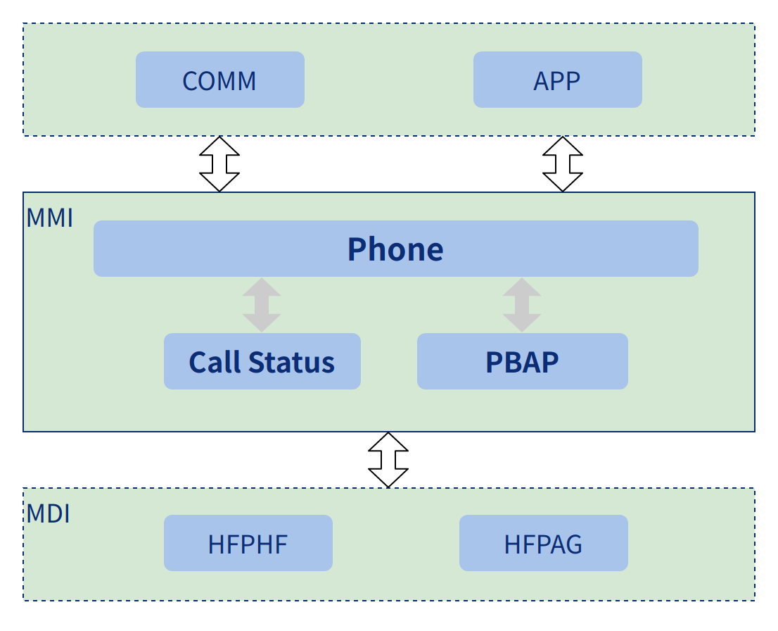
Important Process
Phone Flowchart
The Phone process includes voice dialing, redialing calls, answering calls, rejecting calls and hanging up calls. There is also a logical flow for phonebook acquisition. As well as sending the corresponding status of each process to the application via the serial module.
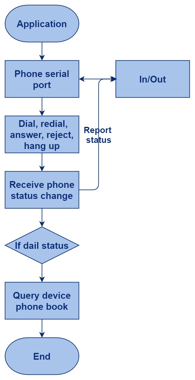
Phone initialization process sequence chart:

Phone call related process sequence chart:
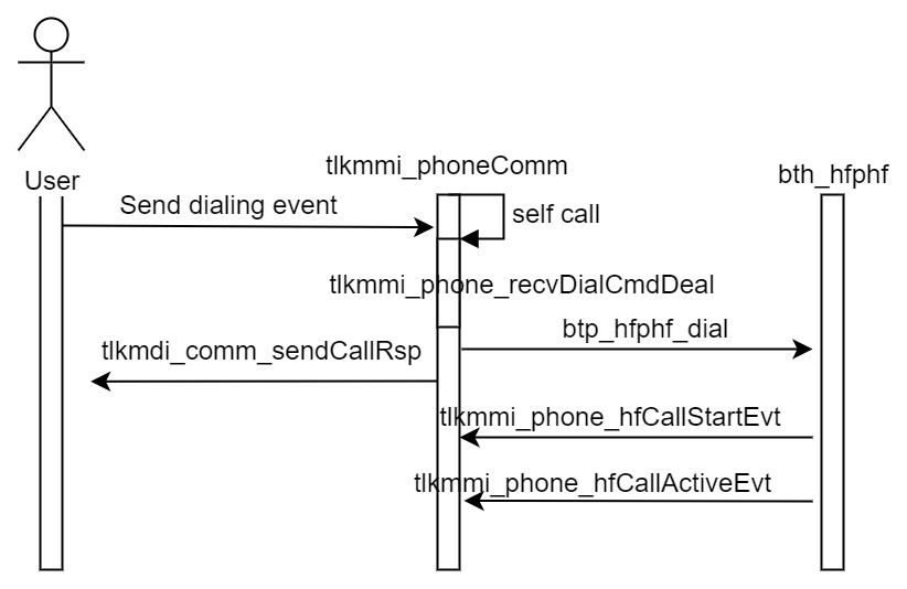
The process of replaying a call, hanging up, etc. is similar to that of making a call above.
Phone Module Design
(1) Phone Interface Design
It is mainly used to describe the interface design in the Phone and the detailed description of the interface design elements, to provide initialization functions for the Phone modules, to configure resources, and etc.
Phone interface design
Macro definition:
Define the enable and disable of Phone DBG info:
#define TLKMMI_PHONE_DBG_FLAG (TLKMMI_PHONE_DBG_ENABLE | TLKAPI_DBG_FLAG_ALL)
Define the phone DBG info sign:
#define TLKMMI_PHONE_DBG_SIGN "[MMI]"
Main interface:
int tlkmmi_phone_init(void)
a) Phone Ctrl module initialization
b) Phone Comm module initialization
c) Phone Book module initialization
d) Phone Status module initialization
(2) Phone Serial Module Design
The main purpose is to describe the interface design in the serial port of the Phone and the detailed description of the interface design elements. The application can send commands and receive command responses and events via the serial interface, enabling the Phone to perform actions and report on the execution status.
Phone Serial Module Design
Main interface:
Register the callback function:
int tlkmmi_phone_commInit(void)
(3) Phone Book Module Design
It is mainly used to describe the data structure and interface design in PhoneBook and the detailed description of the design elements, to provide the interface for querying, storing and erasing the phone book, and to report the results of PhoneBook.
Phone Book Module Design
Macro definitions:
Define the maximum length of the address book name:
#define TLKMMI_PHONE_NAME_MAX_LEN 32
Define the head length of the phone book:
#define TLKMMI_PHONE_BOOK_HEADLEN 16
Define the initialization flag of the phone book:
#define TLKMMI_PHONE_BOOK_FLAG_INIT 0xFF
Define the write flag for the phone book.
#define TLKMMI_PHONE_BOOK_FLAG_WRITE 0xFE
Define the completion flag for the phone book:
#define TLKMMI_PHONE_BOOK_FLAG_COMPLATE 0xF0
Define the storage identifier for the phone book:
#define TLKMMI_PHONE_BOOK_SIGN 0x50424150
Define the length of the stored records in the phone book:
#define TLKMMI_PHONE_BOOK_ITEM_LENGTH (BTP_PBAP_CALL_NAME_LENGTH2+BTP_PBAP_CELL_NUMB_LENGTHBTP_PBAP_CELL_NUMB_COUNT)
#define TLKMMI_PHONE_BOOK_MAX_ITEM_NUMB ((TLK_CFG_FLASH_PBAP_LIST_LENS-32)/TLKMMI_PHONE_BOOK_ITEM_LENGTH)
Defines the number of records stored in the phone book.
Data structure:
typedef struct{
        uint32 pbapSign;
        uint08 btAddr[6];
        uint08 itemLens;
        uint08 callFlag;
        uint32 callNumb;
}__attribute__ ((__packed__)) tlkmmi_phoneBookHead_t;
- pbapSign: pbap business sign
- btAddr: Bluetooth address
- itemLens: pbap content length
- callFlag: execution status
- callNumb: call number
typedef struct{
        uint08 isBusy;
        uint08 isReady;
        uint16 aclHandle;
        uint08 btAddr[6];
        uint32 bookCount;
        tlkapi_timer_t timer;
}tlkmmi_phoneBookCtrl_t;
- isBusy: whether it is executing.
- isReady: whether it is Ready
- aclHandle: Acl mark
- btAddr: Bluetooth address
- bookCount: pbap count
- timer: execution timer
Interface definition:
The following interface has the functions below:
int tlkmmi_phone_bookInit(void)
a) Initialize sTlkMmmiPhoneBookCtrl
b) Register callback function
c) Read flash info from the Flash
Determin whether the current Pbap info is valid:
bool tlkmmi_phone_bookInfoValid(uint08 *pBtAddr)
Clear Pbap information:
void tlkmmi_phone_bookCleanInfo(void)
Syncronize Pbap information:
int tlkmmi_phone_startSyncBook(uint16 aclHandle, uint08 *pBtAddr, bool isForce)
Close pbap syncronization and erase the previous information:
int tlkmmi_phone_closeBookSync(uint16 aclHandle)
int tlkmmi_phone_bookGetName(uint08 *pNumber, uint08 numbLen, uint08 *pName, uint08 nameLen, uint08 *pGetLen);
Get the name from pbap information.
(4) Pbap Status Module Definition
The main purpose is to describe the design of the interface in Phone Status and the detailed description of the design elements, mainly providing some status callback events for the execution of actions, phone start status reporting, phone ring status reporting, phone connect status reporting, phone hang up status reporting.
Pbap Status Module definition
Interface definition:
Register callback function of Call Evt:
int tlkmmi_phone_statusInit(void)
Common Modules
Since the MMI module is an interface for user services, MDI must provide functional support related to the service module. From the content, it is divided into four parts: system call, serial communication, BT link, and business logic. System call and serial communication are the basic modules, which are the basis of MDI layer scheduling and operation and human-machine interaction; BT link provides the MMI layer with functions such as discovery, linking, disconnecting, and reconnecting through the interface of the encapsulated protocol stack; business logic (Audio business logic, Phone business logic) will provide the interface and usage strategy of Audio and the interface and usage strategy of Phone. The content of this section of MDI is mainly divided into organizational structure, operation process, common interface, Bluetooth module design, Audio module design and Phone module design.
Organizational Structure
The structure diagram mainly describes each module and the relationship between each module. The structure of MDI is mainly composed of Basic module, BT module, Audio module and Phone module. The components of the basic module are MDI Adapt, MDI Event, MDI Comm.
- MDI Adapt: Responsible for event scheduling and timer event scheduling, each module will use the timer scheduling logic and event scheduling logic to handle certain missed actions or switching of certain events, etc.;
- MDI Event: Responsible for sending the events generated during the execution of Audio and Phone to the MMI layer, after the MMI layer receives the event, it starts the callback function to execute the corresponding next logical behavior, including Play/Tone/Src/HF/AG of MDI Audio and Phone;
- MDI Comm: Responsible for receiving and sending serial port data to realize human-machine interaction.
The MDI BT module is used to provide discovery and link reconnection functions, and consists of three modules: INQ, ACL and REC:
- INQ: Mainly responsible for the discovery function of the device;
- ACL: Mainly responsible for the link function of the device and the link function of the Profile;
- REC: Mainly responsible for the reconnection function of the device.
MDI Audio is responsible for MMI Audio related business logic scheduling, including the priority scheduling strategy when multiple Audio tasks are running, the Volume state of each Audio task and the Music state under the Audio task. Its main components are AudPlay, AudTone, AudSrc, AudSCO, AudSnk, AudHFP:
- AudPlay: Mainly responsible for local broadcast business;
- AudTone: Mainly responsible for the prompt tone business;
- AudSrc: Mainly responsible for the business of A2DP Source;
- AudSnk: Mainly responsible for the business of A2DP Sink;
- AudHFP: Reserve.
MDI Phone is responsible for functions such as dialing, closing, and replaying calls in Voice Call and monitoring the state changes during the phone call. It consists of Phone and PBAP:
- Phone: Mainly responsible for telephone functions;
- PBAP: Mainly responsible for the phone book function.
Specifically as shown in the figure below:
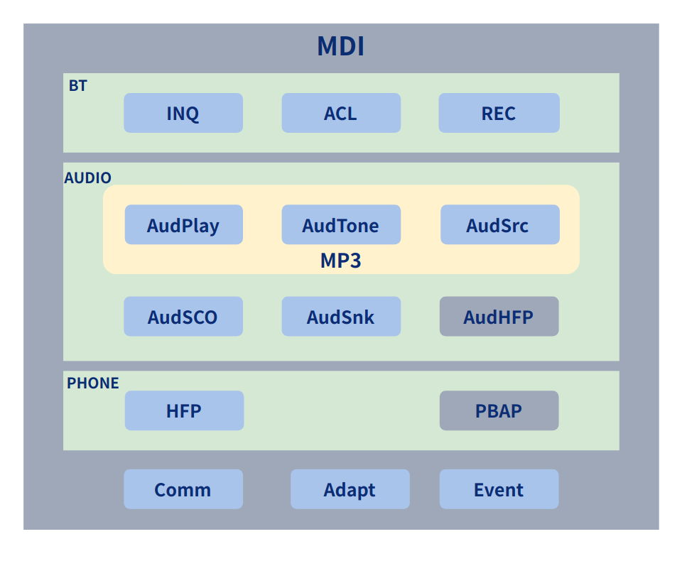
Operation Process
The following is a comprehensive and simple flow chart, which includes the BT link and Profile link business, the various businesses of Audio, and the various businesses of Phone. There are more detailed flow charts in each section, if you want to know more design details of the code, you can refer to the execution flow sequence and interface design of each module:
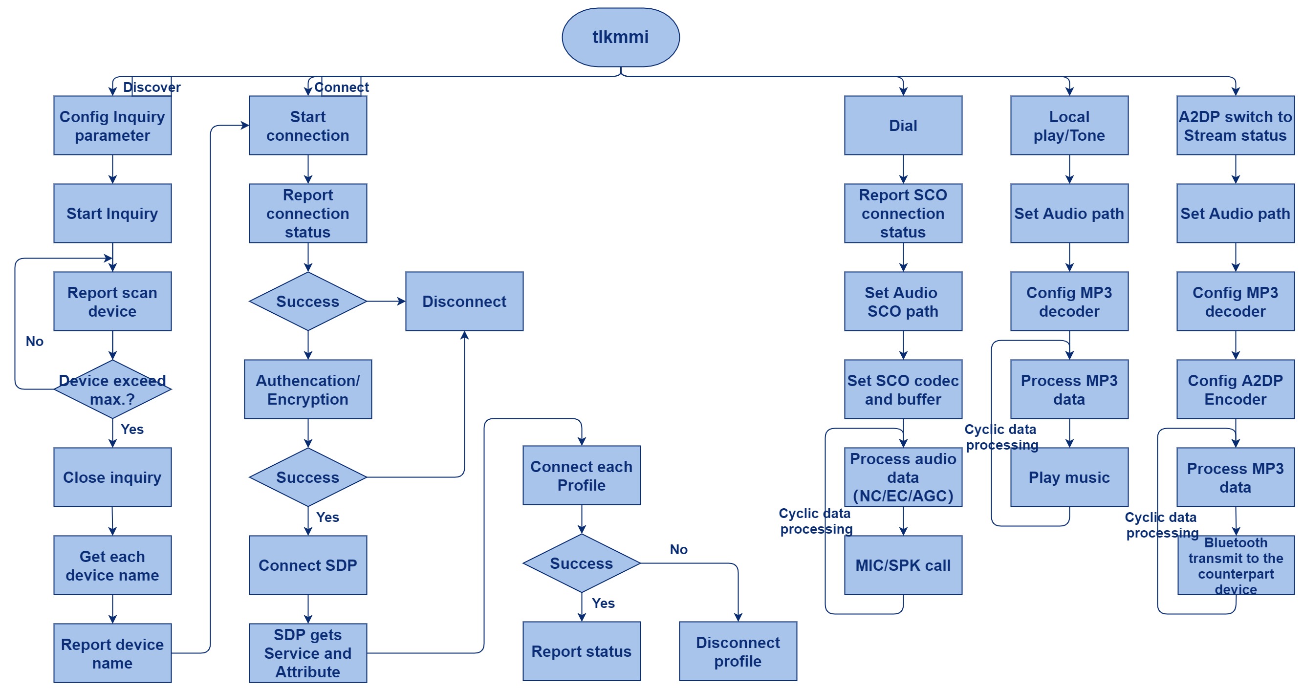
The initialization of MDI is mainly responsible for the initialization of the data structure of each sub-module and the configuration of related parameters. The following is the sub-sequence diagram of the MDI initialization process:

This is a sequence diagram of starting the MDI Handler. The MDI module is executed under the cycle of the SDK, and the serial commands are processed through the handler of the Comm module, the serial port will call the handler of the device Serial, and then handle events such as timer and procs through the handler of Adapt, and finally the callback event will be processed through event. The order between these handlers is strict, and each cycle of the SDK will be executed in the order.
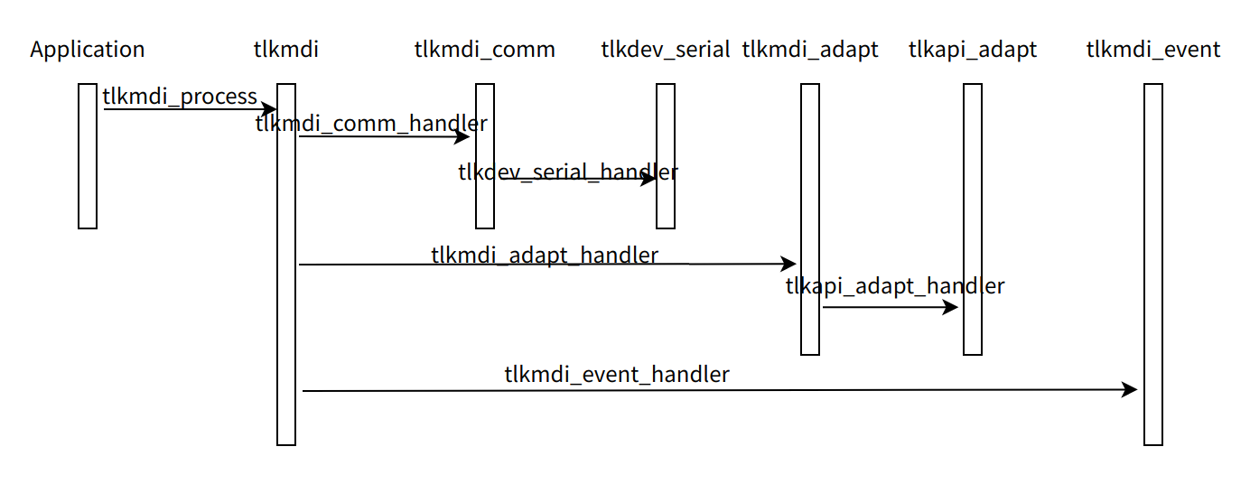
General Interface
The general interface is the basis for the execution of MDI modules. These basic modules provide scheduling resources, serial resources and event callback resources required for MDI to run. Because it is the basis of execution, it does not provide flow chart and process sub-sequence diagram of these general interfaces, but only provides interface design. In the flow chart or process sub-sequence diagram of each business, the general interface will be reflected. The generic interfaces mainly include Adapt, Event, Comm and other interfaces.
Adapt Interface Description
This module mainly encapsulates the scheduling strategy of timer and message. In this module, start the future execution of a function by controlling the timeout duration of the timer. For example, if a play is currently not successfully executed because other events are being executed, through the timer, it can control this event to be executed again. Or control the execution of the message queue, such as the change notification of MP3 song progress bar, MP3 song changes, etc.
MDI Adapt design
Interface function:
Initialize sTlkMdiAdapt:
int tlkmdi_adapt_init(void)
Handling timer events and messages in sTlkMdiAdapt:
void tlkmdi_adapt_handler(void)
Determine whether the current message is being executed, or whether the timer is being executed:
bool tlkmdi_adapt_isbusy(void)
Start a timer:
- pTimer: timer
- timerCB: callback of timer
- pUsrArg: parameter
- timeout: timeout of timer
int tlkmdi_adapt_initTimer(tlkapi_timer_t *pTimer, TlkApiTimerCB timerCB, void *pUsrArg, uint32 timeout);
Start message processing:
- pProcs: message
- procsCB: message handler function
- pUsrArg: message handling function parameter
int tlkmdi_adapt_initProcs(tlkapi_procs_t *pProcs, TlkApiProcsCB procsCB, void *pUsrArg);
Remove pTimer from the Timer list:
void tlkmdi_adapt_deinitTimer(tlkapi_timer_t *pTimer)
Remove pProcs from the Proc list:
void tlkmdi_adapt_deinitProcs(tlkapi_procs_t *pProcs)
Determine whether the current pTimer is in sTlkMdiAdapt:
bool tlkmdi_adapt_isHaveTimer(tlkapi_timer_t *pTimer)
Determine whether the current pProcs is in sTlkMdiAdapt:
bool tlkmdi_adapt_isHaveProcs(tlkapi_procs_t *pProcs)
Add the current pProcs to sTlkMdiAdapt:
int tlkmdi_adapt_appendProcs(tlkapi_procs_t *pProcs)
Remove the current pProcs from sTlkMdiAdapt:
int tlkmdi_adapt_removeProcs(tlkapi_procs_t *pProcs)
Update pTimer's timeout:
int tlkmdi_adapt_updateTimer(tlkapi_timer_t *pTimer, uint32 timeout)
Add the current pTimer to sTlkMdiAdapt:
int tlkmdi_adapt_insertTimer(tlkapi_timer_t *pTimer)
Remove the current pTimer from sTlkMdiAdapt:
int tlkmdi_adapt_removeTimer(tlkapi_timer_t *pTimer)
Event Interface Description
The event module mainly handles various event callbacks between MMI and MDI by maintaining an event queue, MDI puts the callback events of Audio or Phone into the event queue, and then the MMI layer will process the callback functions one by one, so that the events generated by the bottom layer are executed correctly at the MMI or application layer.
MDI Event design
Data structure:
Define two types of events, Audio and Phone:
typedef enum{
        TLKMDI_EVENT_MAJOR_NONE = 0,
        TLKMDI_EVENT_MAJOR_AUDIO,
        TLKMDI_EVENT_MAJOR_PHONE,
        TLKMDI_EVENT_MAJOR_MAX,
}TLKMDI_EVENT_MAJOR_ENUM
typedef enum{
        TLKMDI_EVENT_MINOR_NONE = 0,
}TLKMDI_EVENT_MINOR_ENUM
Define callback function type:
Define callback function type:
typedef void(*TlkMdiEventCallback)(uint08 majorID, uint08 minorID, uint08 *pData, uint08 dataLen)
Global variable:
Define event buffer:
uint08 sTlkMdiEventBuffer[TLKMDI_EVENT_BUFFER_SIZE]
Define event fifo:
tlkapi_qfifo_t sTlkMdiEventQFifo
Interface definition:
Initialize callback and initialize fifo:
int tlkmdi_event_init(void)
Register the event callback function of Audio or Phone:
void tlkmdi_event_regCB(TLKMDI_EVENT_MAJOR_ENUM type, TlkMdiEventCallback cb)
Clear event fifo:
void tlkmdi_clear_event(void)
Get the number of used event fifo:
uint tlkmdi_event_count(void)
Distribute the acquired event through the callback function:
void tlkmdi_event_handler(void)
Send Audio event:
int tlkmdi_sendAudioEvent(uint08 minorID, void *pData, uint08 dataLen)
Send Phone event:
int tlkmdi_sendPhoneEvent(uint08 minorID, void *pData, uint08 dataLen)
Comm Interface Description
The serial port is mainly used for human-machine interaction or interaction with the client app, through the serial port interaction cmd, Rsp and events etc. to trigger the execution of different processes, so that the whole SDK to perform user actions, such as querying, connecting and playing music etc.
MDI Serial design
Macro definition:
Define the maximum number of data Channel:
#define TLKMDI_COMM_DATA_CHANNEL_MAX 8
Define the callback function type:
Define the type of the command callback function:
typedef void(*tlkmdi_comm_cmdCB)(uint08 msgID, uint08 *pData, uint08 dataLen);
Define the type of the data callback function:
typedef void(*tlkmdi_comm_datCB)(uint16 datID, uint16 number, uint08 *pData, uint08 dataLen);
Interface functions:
Initialize serial, and register serial callback function:
int tlkmdi_comm_init(void)
Serial event handler:
void tlkmdi_comm_handler(void)
Register serial data callback function:
int tlkmdi_comm_regDatCB(uint16 datID, tlkmdi_comm_datCB datCB, bool isForce)
Register system callback function:
void tlkmdi_comm_regSysCB(tlkmdi_comm_cmdCB cmdCB)
Register BT callback function:
void tlkmdi_comm_regBtCB(tlkmdi_comm_cmdCB cmdCB)
Register BLE callback function:
void tlkmdi_comm_regLeCB(tlkmdi_comm_cmdCB cmdCB)
Register debug callback function:
void tlkmdi_comm_regDbgCB(tlkmdi_comm_cmdCB cmdCB)
Register file operation callback function:
void tlkmdi_comm_regFileCB(tlkmdi_comm_cmdCB cmdCB)
Register Phone callback function:
void tlkmdi_comm_regCallCB(tlkmdi_comm_cmdCB cmdCB)
Register Audio callback function:
void tlkmdi_comm_regAudioCB(tlkmdi_comm_cmdCB cmdCB)
Send system command:
int tlkmdi_comm_sendSysCmd(uint08 cmdID, uint08 *pData, uint08 dataLen)
Send system response:
int tlkmdi_comm_sendSysRsp(uint08 cmdID, uint08 status, uint08 reason, uint08 *pData, uint08 dataLen)
Send system event:
int tlkmdi_comm_sendSysEvt(uint08 evtID, uint08 *pData, uint08 dataLen)
Send BT cmd:
int tlkmdi_comm_sendBtCmd(uint08 cmdID, uint08 *pData, uint08 dataLen)
Send BT RSP:
int tlkmdi_comm_sendBtRsp(uint08 cmdID, uint08 status, uint08 reason, uint08 *pData, uint08 dataLen)
Send BT EVT:
int tlkmdi_comm_sendBtEvt(uint08 evtID, uint08 *pData, uint08 dataLen)
Send BLE command:
int tlkmdi_comm_sendLeCmd(uint08 cmdID, uint08 *pData, uint08 dataLen)
Send BLE Resp:
int tlkmdi_comm_sendLeRsp(uint08 cmdID, uint08 status, uint08 reason, uint08 *pData, uint08 dataLen)
Send BLE EVT:
int tlkmdi_comm_sendLeEvt(uint08 evtID, uint08 *pData, uint08 dataLen)
Send File command:
int tlkmdi_comm_sendFileCmd(uint08 cmdID, uint08 *pData, uint08 dataLen)
Send File Resp:
int tlkmdi_comm_sendFileRsp(uint08 cmdID, uint08 status, uint08 reason, uint08 *pData, uint08 dataLen)
Send File Evt:
int tlkmdi_comm_sendFileEvt(uint08 evtID, uint08 *pData, uint08 dataLen)
Send Call command:
int tlkmdi_comm_sendCallCmd(uint08 cmdID, uint08 *pData, uint08 dataLen);
Send Phone Resp:
int tlkmdi_comm_sendCallRsp(uint08 cmdID, uint08 status, uint08 reason, uint08 *pData, uint08 dataLen)
Send Phone EVT:
int tlkmdi_comm_sendCallEvt(uint08 evtID, uint08 *pData, uint08 dataLen)
Send Audio command:
int tlkmdi_comm_sendAudioCmd(uint08 cmdID, uint08 *pData, uint08 dataLen)
Send Audio Resp:
int tlkmdi_comm_sendAudioRsp(uint08 cmdID, uint08 status, uint08 reason, uint08 *pData, uint08 dataLen)
Send Audio Evt:
int tlkmdi_comm_sendAudioEvt(uint08 evtID, uint08 *pData, uint08 dataLen)
Send command:
int tlkmdi_comm_sendCmd(uint08 mType, uint08 cmdID, uint08 *pData, uint08 dataLen)
Send resp:
int tlkmdi_comm_sendRsp(uint08 mType, uint08 cmdID, uint08 status, uint08 reason, uint08 *pData, uint08 dataLen)
Send evt:
int tlkmdi_comm_sendEvt(uint08 mType, uint08 msgID, uint08 *pData, uint08 dataLen)
Send data:
int tlkmdi_comm_sendDat(uint08 datID, uint16 numb, uint08 *pData, uint16 dataLen)
Other Interface Description
This module is the initial interface for the entire MMI to call MDI. Through this module, other modules of the MDI layer are initialized, and interfaces for Adapt and Event processing functions are provided, as well as an interface to determine whether Adapt and Event are currently working.
MDI Interface design
Interface definition:
This interface has the following functions:
int tlkmdi_init(void)
(1) Initialize serial
(2) Adapt initialization
(3) Event initialization
(4) acl link management initialization
(5) Inquiry management initialization
(6) rect management initialization
(7) MP3/ play/ tone/ hfp/ sco/ a2dp initialization
Determine the number of events in fifo or whether the Adapt is working:
bool tlkmdi_isbusy(void)
This interface has the following functions:
void tlkmdi_process(void)
(1) Execute the processing function of Adapt
(2) Execute the processing function of Event
PMQuery whether you can currently enter PM:
bool tlkmdi_pmIsbusy(void)
Bluetooth Module Design
The Bluetooth module is the premise of business execution on the device. It encapsulates the discovery and connection interface of the Bluetooth protocol, and provides the MMI with Bluetooth functions such as discovery and connection and reconnection. It is composed of three parts, the first is discovery; the second is connection; and the third is reconnection.
BTINQ Design and Implementation
(1) Module Introduction
This module is mainly used to encapsulate the interface of the Inquiry function, which is convenient for MMI layer access and easy for subsequent development. It provides some basic strategies for using Inquiry to ensure that the various actions of MMI layer users are executed correctly.
(2) Status Conversion
The discovery module has designed the following state machine, which consists of Idle, Opening, Closing, Inquiry and GetName. In the Idle state, the device is in a silent state; the Opening state is when the MMI initiates an Inquiry request and needs to set the parameters required by the Inquiry process to the Controller, at this time, the state of the BTINQ module will enter from Idle to Opening. If the parameter fails or the MMI layer cancels the Inquiry, it will enter the Closing state; the Inquiry state is that after the Opening is executed and the Inquiry command is initiated, it will enter this state. In this state, the device will initiate Inquiry, and then report the queried devices, when the number of discovered devices reaches the upper limit or the Inquiry fails or is cancelled, it will end the Inquiry and enter the Closing state. The GetName state is used to query the name of the device, compared with Inquiry, it is an independent process, after the device name is obtained, it will enter the Closing state. The Closing state is entered when Opening, Inquiry and GetName are ended, and then enters the Idle state.
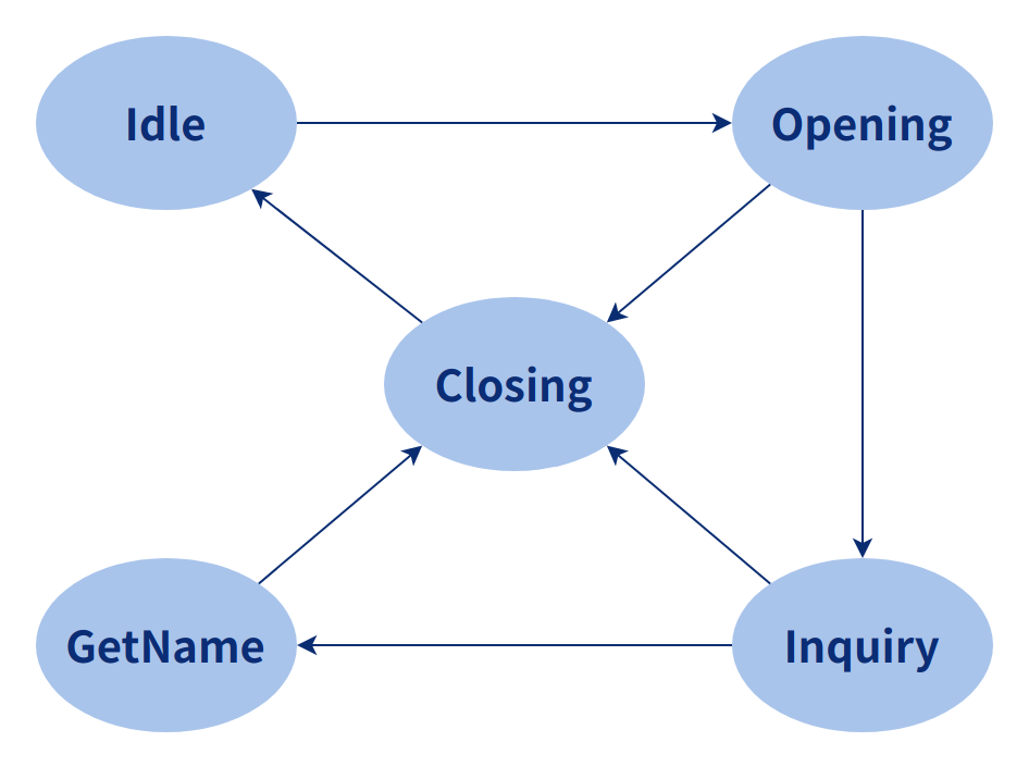
(3) Operation Process
The entire process of discovery consists of three parts: INIT, Inquiry and GetName. The flow chart is as follows.
After the initialization is completed, it will then determine whether the GetName (device name acquisition) process is enabled. If the process is not enabled, it will immediately determine whether the inquiry (device query) process is enabled. If the Inquiry process is not enabled, the parameter will be reset. When the Inquiry is triggered, it will enter the Inquiry state, in this state, the device will continuously query the surrounding devices and report them. The Inquiry will keep executing the device query until it is finished. When the Inquiry ends or reaches the window size of the Inquiry, it exits the Inquiry state and enters the GetName state, when the device name is obtained, it exits the GetName state and enters the Inquiry process again.
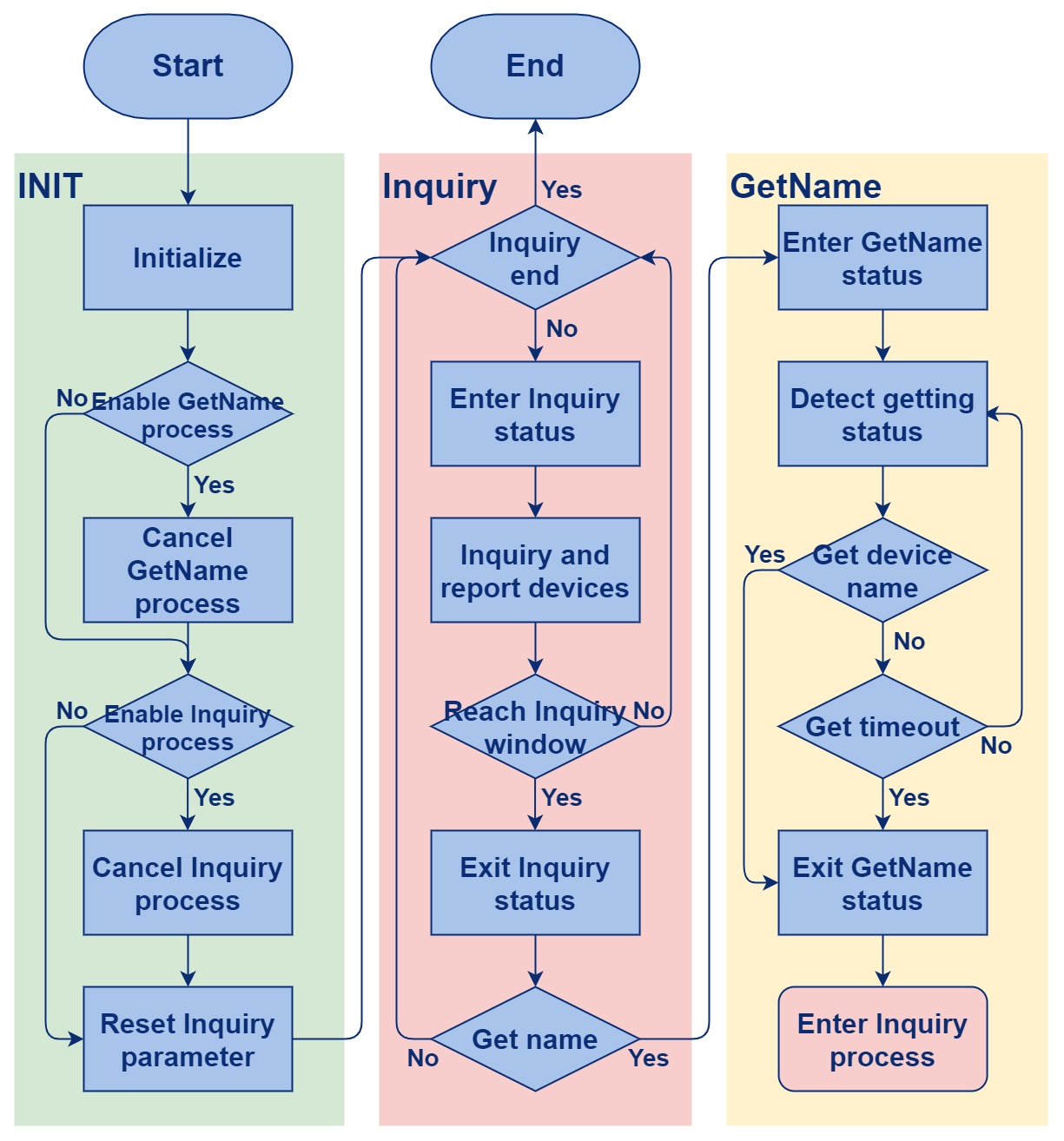
The discovered subsequence flow chart is as follows:
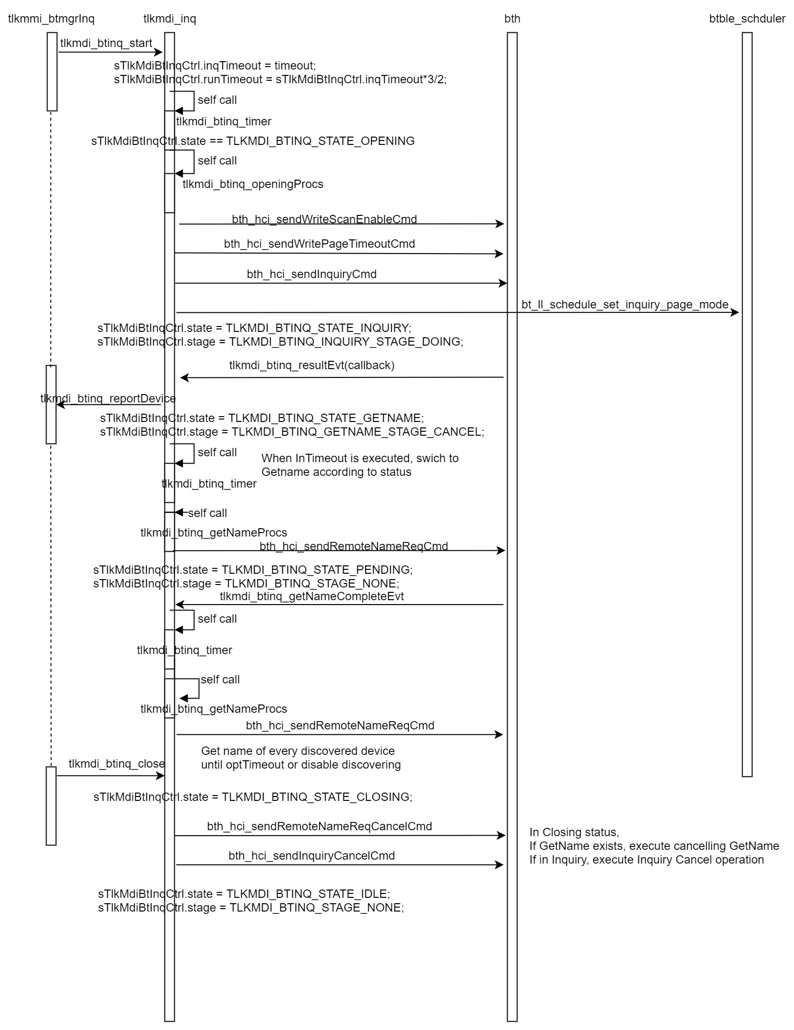
(4) Interface Description
The interface consists of four parts, the module name of the first part; the design classification of the second part, the design details of the third part and the detailed interpretation of the fourth part.
MDI Inquiry design
Macro definition:
Define inquiry timeout:
#define TLKMDI_BTINQ_TIMEOUT 100000
Define the maximum number of inquiry:
#define TLKMDI_BTINQ_TIMEOUT_MS (TLKMDI_BTINQ_TIMEOUT/1000)
Define the timeout for getname execution:
#define TLKMDI_BTINQ_WAIT_GETNAME_TIMEOUT (3000000/TLKMDI_BTINQ_TIMEOUT)
Define the timeout for execution in the wait state:
#define TLKMDI_BTINQ_WAIT_CANCEL_TIMEOUT (3000000/TLKMDI_BTINQ_TIMEOUT)
Define the length of the discovered device name:
#define TLKMDI_BTINQ_NAME_LENS 19
Define the number of discovered devices:
#define TLKMDI_BTINQ_ITEM_NUMB 15
Data structure:
Define discovered device types:
typedef enum{
        TLKMDI_BTINQ_DTYPE_MISC       = 0x00,
        TLKMDI_BTINQ_DTYPE_PC         = 0x01,
        TLKMDI_BTINQ_DTYPE_PHONE      = 0x02,
        //TLKMDI_BTINQ_DTYPE_NET      = 0x03,
        TLKMDI_BTINQ_DTYPE_HEADSET    = 0x04,
        //TLKMDI_BTINQ_DTYPE_KEYBOARD = 0x05,
        //TLKMDI_BTINQ_DTYPE_SPP      = 0x0F,
        TLKMDI_BTINQ_DTYPE_UNKNOWN    = 0xFF,
}TLKMDI_BTINQ_DTYPE_ENUM;
- PC
- Phone
- Network_dev
- Headset
- Keyboard
- Spp
The various states of the Inquiry:
- Idle
- Opening
- Inquiry
- GetName
- For Get Name
- Closing
typedef enum{
        TLKMDI_BTINQ_STATE_IDLE = 0,
        TLKMDI_BTINQ_STATE_OPENING,
        TLKMDI_BTINQ_STATE_INQUIRY,
        TLKMDI_BTINQ_STATE_GETNAME,
        TLKMDI_BTINQ_STATE_PENDING,
        TLKMDI_BTINQ_STATE_CLOSING,
}TLKMDI_BTINQ_STATE_ENUM;
Define the action under the special phase of Inquiry:
typedef enum{
 TLKMDI_BTINQ_STAGE_NONE = 0,
 TLKMDI_BTINQ_OPENING_STAGE_CLOSE_SCAN = 1,
 TLKMDI_BTINQ_OPENING_STAGE_SET_TIMEOUT,
TLKMDI_BTINQ_OPENING_STAGE_START_INQUIRY,
TLKMDI_BTINQ_OPENING_STAGE_SET_SCHEDULE,
TLKMDI_BTINQ_INQUIRY_STAGE_CANCEL = 1,
TLKMDI_BTINQ_INQUIRY_STAGE_WAIT,
TLKMDI_BTINQ_INQUIRY_STAGE_START,
TLKMDI_BTINQ_INQUIRY_STAGE_DOING,
TLKMDI_BTINQ_GETNAME_STAGE_CANCEL = 1
TLKMDI_BTINQ_GETNAME_STAGE_CLOSING,
TLKMDI_BTINQ_GETNAME_STAGE_WAITING,
TLKMDI_BTINQ_GETNAME_STAGE_OPENING,
TLKMDI_BTINQ_CLOSING_STAGE_CANCEL_GETNAME = 1,
 TLKMDI_BTINQ_CLOSING_STAGE_WAIT_GETNAME,
 TLKMDI_BTINQ_CLOSING_STAGE_CANCEL_INQUIRY,
 TLKMDI_BTINQ_CLOSING_STAGE_WAIT_INQUIRY,
TLKMDI_BTINQ_CLOSING_STAGE_INQUIRY_OVER,
}TLKMDI_BTINQ_STAGE_ENUM;
- Close scan in Opening state
- Set timeout in Opening state
- Start inquiry in Opening state
- Set schedule in Opening state
- Cancel in Inquiry state
- Wait in Inquiry state
- Start in Inquiry state
- Doing in Inquiry state
- Cancel in GetName state
- Closing in GetName state
- Waiting in GetName state
- Opening in GetName state
- Cancel getname in Closing state
- Wait getName in Closing state
- Cancel Inquiry in Closing state
- Wait Inquiry in Closing state
- Inquiry over in Closing state
Define Inquiry item state:
typedef enum{
        TLKMDI_BTINQ_ITEM_STATE_NONE = 0,
        TLKMDI_BTINQ_ITEM_STATE_WAIT,
        TLKMDI_BTINQ_ITEM_STATE_OVER,
}TLKMDI_BTINQ_ITEM_STATE_ENUM;
- Inquiry item state Wait
- Inquiry item state Over
Define the following data structure:
typedef struct{
        uint08 rssi;
        uint08 state;
        uint08 smode;
        uint08 dtype;
        uint08 nameLen;
        uint16 clkOff;
        uint32 devClass;
        uint08 btaddr[6];
        uint08 btname[TLKMDI_BTINQ_NAME_LENS+1];
}tlkmdi_btinq_item_t;
- rssi: signal strength
- state: inquiry item state
- Smode: scan mode
- dtype: device type
- nameLen: device name length
- clkOff: clock offset compensation
- devClass: device class
- btaddr: bluetooth device address
- btname: bluetooth name
Define the following data structure:
typedef struct{
        uint08 state;
        uint08 busys;
        uint08 stage;
        uint08 inqType;
        uint08 curNumb;
        uint08 maxNumb;
        uint08 nameIdx;
        uint08 rssiThd;
        uint08 getName;
        uint16 optTimeout;
        uint16 runTimeout;
        uint16 inqTimeout;
        tlkapi_timer_t timer;
        tlkmdi_btinq_item_t item[TLKMDI_BTINQ_ITEM_NUMB];
}tlkmdi_btinq_ctrl_t;
- state: inquiry state
- busys: mark the action that is not currently executing properly
- stage: mark the action in different states
- inqType: inquiry types, including // pc: 1, phone: 2, network_dev: 3, headset: 4, keyboard: 5, spp_dev: 0x0f;
- curNumb: current number of devices
- nameIdx: device name index
- rssiThd: signal intensity threshold
- getName: inquiry name
- optTimeout: operation timeout duration
- runTimeout: run timeout
- inqTimeout: inquiry duration
- timer: inquiry timer
Callback function type definition:
Inquiry result callback function:
typedef int(*TlkMmiBtInqReportCallBack)(uint32 devClass, uint08 rssi, uint08 nameLen, uint08 *pBtaddr, uint08 pBtName);
Inquiry end callback function:
typedef void(TlkMmiBtInqCompleteCallBack)(void);
Interface definition:
This interface has the following functions:
int tlkmdi_btinq_init(void)
(1) Initialize Inquiry's control variable
(2) Initialize timer
(3) Register callback function
Inquire about the current status of Inquiry:
bool tlkmdi_btinq_isBusy(void)
Start Inquiry:
int tlkmdi_btinq_start(uint08 inqType, uint08 rssiThd, uint08 maxNumb, uint16 timeout, bool isGetName);
Close inquiry:
void tlkmdi_btinq_close(void)
Close timer, empty data:
void tlkmdi_btinq_reset(void)
Register the callback function discovered and reported by device:
void tlkmdi_btinq_regCallback(TlkMmiBtInqReportCallBack reportCB, TlkMmiBtInqCompleteCallBack completeCB)
Clear the scanned devices number:
void tlkmdi_btinq_cleanItems(void)
Find the number of devices currently scanned:
int tlkmdi_btinq_getItemCount(void)
Find the device index specified by pAddr:
int tlkmdi_btinq_getItemIndex(uint08 *pAddr)
Find Inquiry's Item by index:
tlkmdi_btinq_item_t *tlkmdi_btinq_getItem(uint08 index)
Find unused Inquiry Item:
tlkmdi_btinq_item_t *tlkmdi_btinq_getIdleItem(void)
Find the Inquiry Item being used according to pAddr:
tlkmdi_btinq_item_t *tlkmdi_btinq_getUsedItem(uint08 *pAddr)
BTACL Design and Implementation
(1) Module Introduction
This module has three functions: first, it encapsulates the calling interfaces of the BT Host and BT Profile layers to prevent users from directly accessing the Host and Profile; the second is to provide the ACL connection strategy to ensure that different user trigger connection behaviors can be executed normally; the third is to provide a connection to the Profile.
(2) Operation Process
The connection flow chart is as follows:
When the ACL connection times out, the connection process ends directly, otherwise the connection event of the ACL is reported, and then the encryption authentication will be enabled. If the encryption authentication fails or the encryption times out, the connection will be ended, otherwise the encryption event is reported, then start the SDP process until it ends, and start to connect each profile. When the profile is successfully connected, the connection process ends after the profile event is reported.
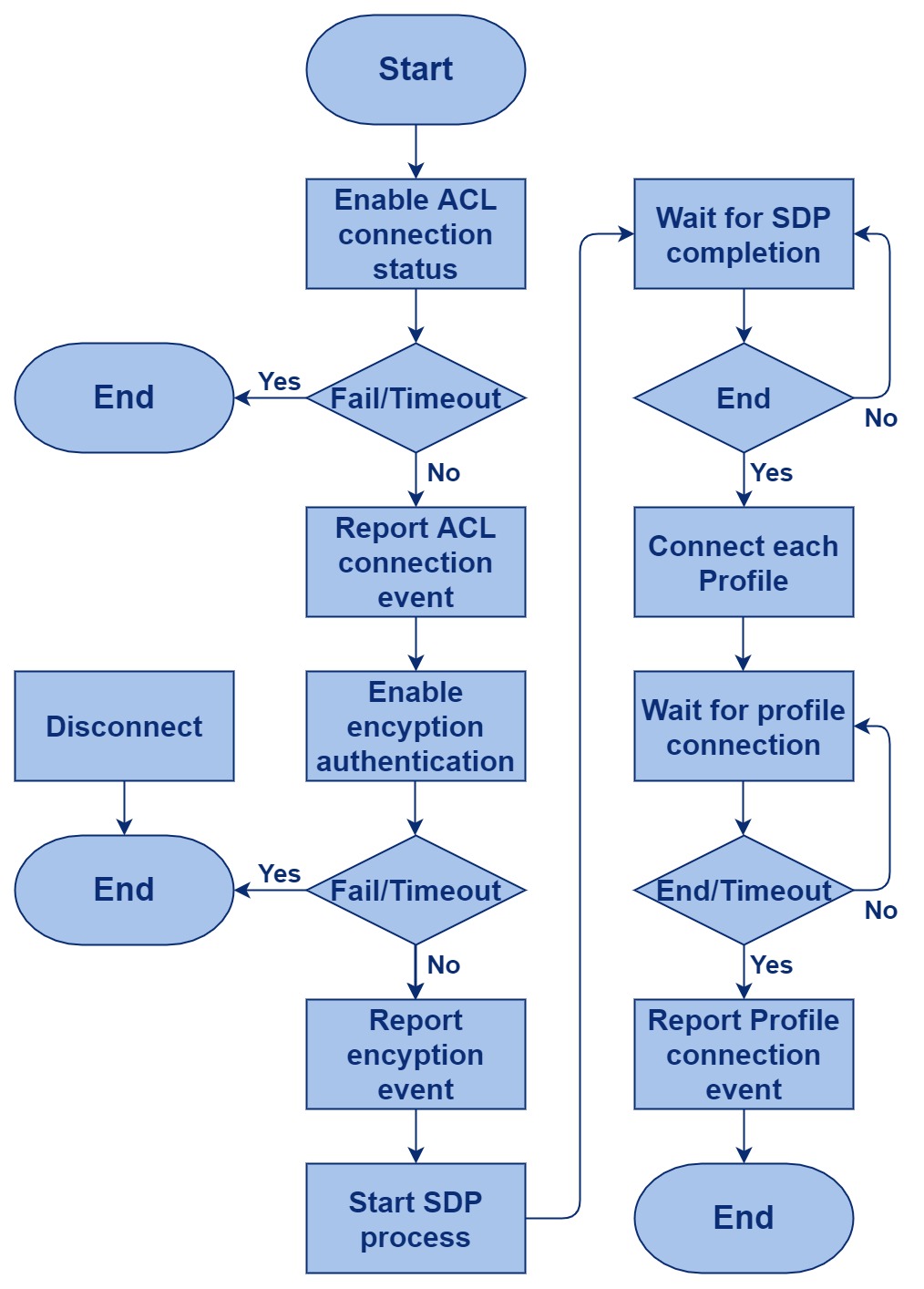
The following is the connection process subsequence diagram :
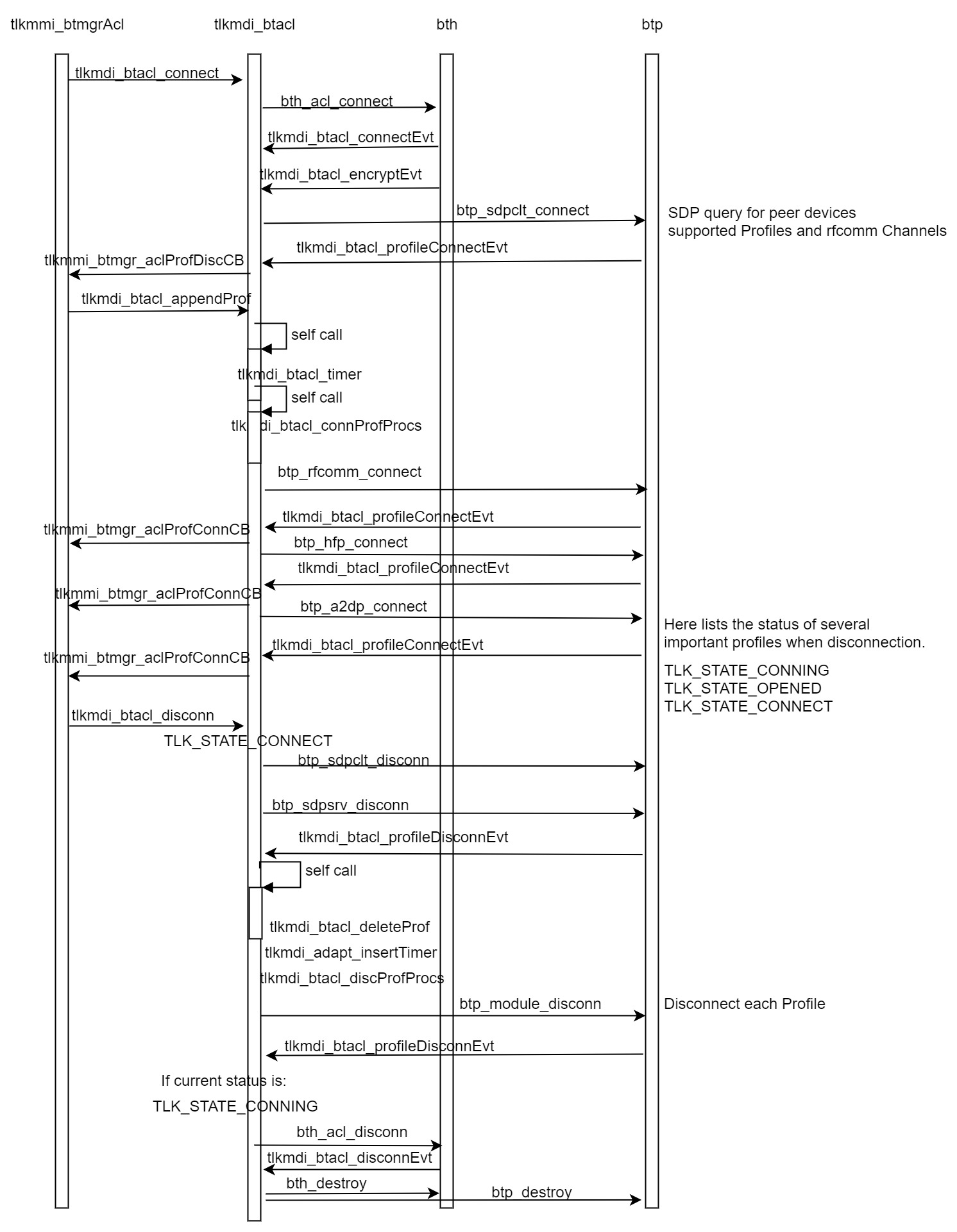
(3) Interface Description
The interface consists of four parts, the module name of the first part; the design classification of the second part, the design details of the third part and the detailed interpretation of the fourth part.
MDI ACL design
Macro definition:
Define the timeout for connection and disconnection:
#define TLKMDI_BTACL_TIMEOUT             200000 //us
#define TLKMDI_BTACL_TIMEOUT_MS          200
#define TLKMDI_BTACL_CONN_DEF_TIMEOUT    (20000000/TLKMDI_BTACL_TIMEOUT)
#define TLKMDI_BTACL_CONN_MIN_TIMEOUT    (10000000/TLKMDI_BTACL_TIMEOUT) //6S
#define TLKMDI_BTACL_CONN_MAX_TIMEOUT    (40000000/TLKMDI_BTACL_TIMEOUT) //40S
#define TLKMDI_BTACL_DISC_DEF_TIMEOUT    (8000000/TLKMDI_BTACL_TIMEOUT)
#define TLKMDI_BTACL_DISC_MIN_TIMEOUT    (5000000/TLKMDI_BTACL_TIMEOUT)
#define TLKMDI_BTACL_DISC_MAX_TIMEOUT    (30000000/TLKMDI_BTACL_TIMEOUT)

#define TLKMDI_BTACL_IDLE_DEF_TIMEOUT    (10000000/TLKMDI_BTACL_TIMEOUT)

#define TLKMDI_BTACL_PROFILE_CONN_TIMEOUT     (15000000/TLKMDI_BTACL_TIMEOUT)
#define TLKMDI_BTACL_PROFILE_DISC_TIMEOUT     (10000000/TLKMDI_BTACL_TIMEOUT)
This interface has the following functions:
#define TLKMDI_BTACL_ITEM_NUMB           TLK_BT_ACL_MAX_NUMB
#define TLKMDI_BTACL_PROF_NUMB           8
- Define the maximum number of ACLs allowed to connect
- Define the maximum number of profiles allowed
Callback function type definition:
typedef void(*TlkMdiBtAclConnCallback)(uint16 handle, uint08 status, uint08 *pBtAddr);
typedef void(*TlkMdiBtAclDiscCallback)(uint16 handle, uint08 reason, uint08 *pBtAddr);
typedef void(*TlkMdiBtAclProfConnCallback)(uint16 handle, uint08 status, uint08 ptype, uint08 usrID, uint08 *pBtAddr);
typedef void(*TlkMdiBtAclProfDiscCallback)(uint16 handle, uint08 reason, uint08 ptype, uint08 usrID, uint08 *pBtAddr);
- ACL connect callback type definition
- ACL disconnect callback type definition
- Profile connect callback type definition
- Profile disconnect callback type definition
Data structure:
Define the following data structure:
typedef enum{
        TLKMDI_BTACL_ATTR_NONE = 0x00,
        TLKMDI_BTACL_ATTR_REQUEST = 0x01,
        TLKMDI_BTACL_ATTR_CONNECT = 0x02,
        TLKMDI_BTACL_ATTR_ENCRYPT = 0x04,
}TLKMDI_BTACL_ATTRS_ENUM;
- TLKMDI_BTACL_ATTR_REQUEST: connection request attribute
- TLKMDI_BTACL_ATTR_CONNECT: connection attribute
- TLKMDI_BTACL_ATTR_ENCRYPT: encryption attribute
Define the following data structure:
typedef enum{
        TLKMDI_BTACL_BUSY_NONE = 0x00,
        TLKMDI_BTACL_BUSY_CONN_PROF  = 0x02,
        TLKMDI_BTACL_BUSY_DISC_PROF  = 0x04,
        TLKMDI_BTACL_WAIT_DISC_PROF  = 0x08,
        TLKMDI_BTACL_BUSY_DISC_RFC   = 0x01,
        TLKMDI_BTACL_WAIT_DISC_RFC   = 0x02,
        TLKMDI_BTACL_BUSY_DISC_ACL   = 0x80,
        TLKMDI_BTACL_WAIT_DISC_ACL   = 0x40,
}TLKMDI_BTACL_BUSYS_ENUM;
- TLKMDI_BTACL_BUSY_CONN_PROF: mark Profile connection as busy
- TLKMDI_BTACL_BUSY_DISC_PROF: mark disconnected Profile as busy
- TLKMDI_BTACL_WAIT_DISC_PROF: mark waiting for Profile to disconnect
- TLKMDI_BTACL_BUSY_DISC_RFC: mark disconnected RF as busy
- TLKMDI_BTACL_WAIT_DISC_RFC: mark waiting for RF to disconnect
- TLKMDI_BTACL_BUSY_DISC_ACL: mark disconnected ACL as busy
- TLKMDI_BTACL_WAIT_DISC_ACL: mark waiting for ACL to disconnect
ACL event:
typedef enum{
        TLKMDI_BTACL_FLAG_NONE = 0x00,
}TLKMDI_BTACL_FLAGS_ENUM;
Define the following data structure:
typedef struct{
        uint08 state;
        uint08 ptype;
        uint08 usrID;
        uint08 cwait;
        uint16 delay; //
}tlkmdi_btacl_prof_t;
- state: connection state of profile
- ptype: profile type
- usrID: mark Client/Server
- cWait: connection wait time
- delay: delay
Define the following data structure:
typedef struct{
        uint08 state;
        uint08 stage;
        uint08 busys;
        uint08 attrs;
        uint08 flags;
        uint16 handle;
        uint16 timeout;
        uint16 connFlag;
        uint16 idleTime;
        uint32 devClass;
        uint08 active;
        uint08 hfpChannel;
        uint08 sppChannel;
        uint08 pbapChannel;
        uint08 btaddr[6];
        tlkapi_timer_t timer;
        tlkmdi_btacl_prof_t prof[TLKMDI_BTACL_PROF_NUMB];
}tlkmdi_btacl_item_t;
- state: connection state
- stage: mark the current stage of execution
- busys: mark whether the execution action is blocked
- attrs: mark request/connect/encrypt events
- flags: Mark connection wait event
- handle: mark acl handle
- timeout: mark timeout
- connFlag: mark Connect flag
- idleTime: mark idle duration
- devClass: peer device type
- active: compare if the link is in use
- hfpChannel: mark hfp Channel
- sppChannel: mark spp Channel
- PbapChannel: mark pbap Channel
- btaddr: mark Bluetooth address
- timer: the timer currently executing the action
- prof: profile array
ACL link management array:
typedef struct{
        tlkmdi_btacl_item_t item[TLKMDI_BTACL_ITEM_NUMB];
}tlkmdi_btacl_ctrl_t;
Interface definition:
Initialize sTlkMdiBtAclCtrl, register each callback function:
int tlkmdi_btacl_init(void)
Determine whether the ACL corresponding to the handle is in the connected state:
bool tlkmdi_btacl_isActive(uint16 handle)
Determine whether there is rfcomm in the ACL link corresponding to the handle:
bool tlkmdi_btacl_isHaveRfc(uint16 handle)
Determine whether there is hfp in the ACL link corresponding to the handle:
bool tlkmdi_btacl_isFindHfp(uint16 handle)
Determine whether there is spp in the ACL link corresponding to the handle:
bool tlkmdi_btacl_isFindSpp(uint16 handle)
Determine whether there is pbap in the ACL link corresponding to the handle:
bool tlkmdi_btacl_isFindPbap(uint16 handle)
Cancel ACL connection:
int tlkmdi_btacl_cancel(uint08 *pBtAddr)
Initiate ACL connection request:
int tlkmdi_btacl_connect(uint08 *pBtAddr, uint32 devClass, uint32 timeout)
Disconnection request:
int tlkmdi_btacl_disconn(uint16 handle, uint08 reaosn)
Add the profile that needs to be connected:
int tlkmdi_btacl_appendProf(uint16 handle, uint08 ptype, uint08 usrID, uint16 delayMs)
Remove connected profile:
int tlkmdi_btacl_removeProf(uint16 handle, uint08 ptype, uint08 usrID)
Get the role of the acl link:
int tlkmdi_btacl_getRole(uint32 devClass)
Register the callback function for the connection:
void tlkmdi_btacl_regConnectCB(TlkMdiBtAclConnCallback callback)
Register the callback function for disconnection:
void tlkmdi_btacl_regDisconnCB(TlkMdiBtAclDiscCallback callback)
Register the callback function for profile connection:
void tlkmdi_btacl_regProfileConnectCB(TlkMdiBtAclProfConnCallback callback)
Register the callback function for profile disconnection:
void tlkmdi_btacl_regProfileDisconnCB(TlkMdiBtAclProfDiscCallback callback)
Get the number of free acl control variables:
uint08 tlkmdi_btacl_getIdleCount(void)
Get the number of acl control variables being connected:
uint08 tlkmdi_btacl_getUsedCount(void)
Get the number of connected acl control variables:
uint08 tlkmdi_btacl_getConnCount(void)
Clear pItem's data:
void tlkmdi_btacl_resetItem(tlkmdi_btacl_item_t *pItem)
Allocate management resource for the ACL to be established:
tlkmdi_btacl_item_t *tlkmdi_btacl_getIdleItem(void)
Get ACL management resource in OPEN state:
tlkmdi_btacl_item_t *tlkmdi_btacl_getInitItem(void)
Find ACL management resource in connected state:
tlkmdi_btacl_item_t *tlkmdi_btacl_getBusyItem(void)
Find the ACL management resource specified by handle:
tlkmdi_btacl_item_t *tlkmdi_btacl_getUsedItem(uint16 handle)
Find the connection management resource specified by handle:
tlkmdi_btacl_item_t *tlkmdi_btacl_getConnItem(uint16 handle)
Find the connection management resource specified by index:
tlkmdi_btacl_item_t *tlkmdi_btacl_getConnItemByIndex(uint08 index)
Find the ACL management resource in the usage state specified by pBtaddr:
tlkmdi_btacl_item_t *tlkmdi_btacl_searchUsedItem(uint08 *pBtAddr)
Find ACL management resources in the connection state specified by pBtaddr:
tlkmdi_btacl_item_t *tlkmdi_btacl_searchConnItem(uint08*pBtAddr)
BTREC Design and Implementation
(1) Module Introduction
This module provides a scheduling strategy related to BT reconnection, which can ensure that the user's reconnection behavior is executed correctly. It is not necessary for the user to design the reconnection strategy separately, but only need to call the relevant interface.
(2) Status Conversion
The reconnection consists of five states, namely Idle, Page, Scan, Keep and Close.
- In the Idle state, if the upper layer requests reconnection, it will enter the Page state. If the current device is in the reconnection state, it will enter the Keep state and wait for the connection of the current device;
- In the Page state, it will switch back and forth between Page and Scan (Page Scan and Inquiry Scan), so there will be a switch between Page state and Scan state. If the Page appears to timeout, it will enter the Keep state, in the Keep state, if the number of Page does not exceed the maximum value, it can also enter the Init state through Close and re-enter the Page state.
- In the Scan state, after querying the device, it will directly start connecting to the Page state. Or enter the Keep state and wait for the external device to discover or connect to this device.
- In the Keep state, when a new page command comes, it will restart the page and enter the Page state; or when a Scan request comes over again, it can enter the Scan state; or end the Keep state and enter the Close state.
- In the Close state, when the activity to stop page has not been completed, it needs to enter the Keep state, wait for the stop page to finish executing, re-enter the Close state, and finally switch to the Idle state. In the Close state, re-initiating the page, or Scan, will re-enter the Page state or the Scan state. The Close state will naturally switch to the Init state.

(3) Operation Process
When BT is in the Init state, after receiving the reconnection request, the system will first initialize the parameters, and then start the process of Scan and Page. First, the connection will be cancelled, and the Page scan and Inquiry scan will be closed. When the page is initiated, it enters the Page state. In this state, start connecting to the target device, if the connection times out, cancel the connection, and check if the current number of connections has been exceeded, when the number of connections is exceeded, it will enter the Scan state, open Inquiry scan and Page scan, and wait for the target device to connect to the local device. When the number of connections in the page state does not exceed the total number, it will enter the Keep state, in the Keep state, it will wait for the end of the execution process of canceling connection. In the Scan state, if the Scan request is not started, it will re-enter the Page state and continue to execute the page process. Or in the Scan state, if the peer device fails to connect to the local device or times out, if the user sets a page request, it will re-enter the Page state to execute the page process again, otherwise it will enter the Keep state and wait for the Scan execution process to exit.
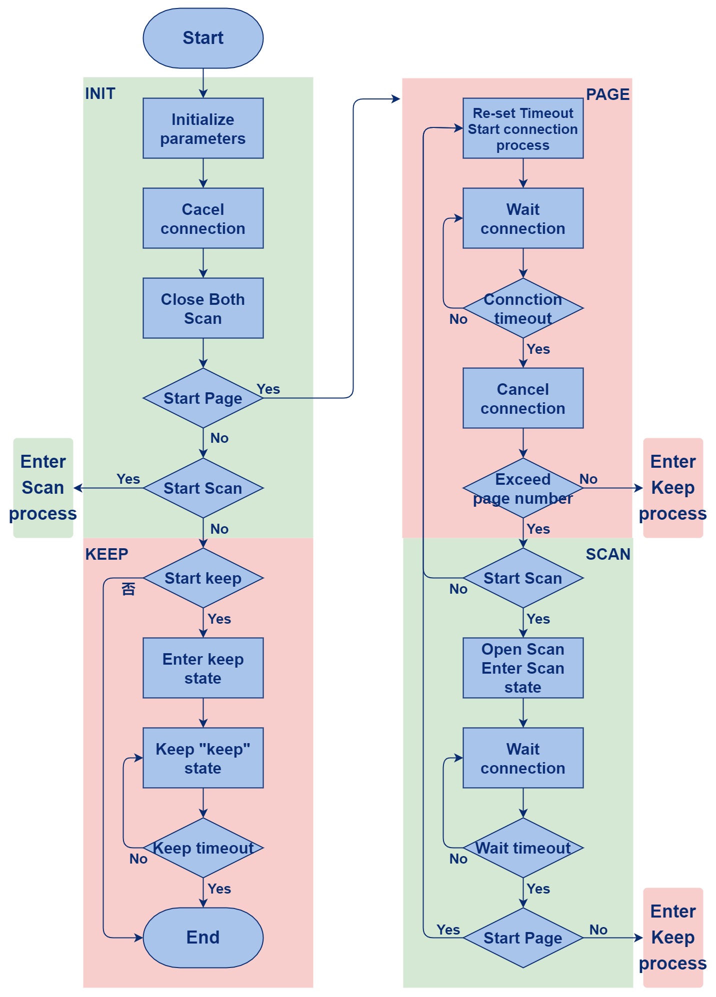
The process sequence diagram is as follows:

(4) Interface Description
This module is mainly used to control the behavior of reconnection, and provide the interface of reconnection and some strategies for the MMI layer.
MDI Reconnect design
Macro definition:
100ms timeout:
#define TLKMDI_BTREC_TIMEOUT          100000
#define TLKMDI_BTREC_TIMEOUT_MS       100
Wait for a while before reconnection is initiated:
#define TLKMDI_BTREC_OPEN_WAIT (200000/TLKMDI_BTREC_TIMEOUT)
After defining each scan switch, follow Step to increase the scan time:
#define TLKMDI_BTREC_SCAN_STEP (500000/TLKMDI_BTREC_TIMEOUT)
Waiting time for switching to page after Inquiry Scan is complete:
#define TLKMDI_BTREC_SCAN_WAIT (200000/TLKMDI_BTREC_TIMEOUT)
When the page is complete, wait a while to switch to Inquiry:
#define TLKMDI_BTREC_PAGE_WAIT (300000/TLKMDI_BTREC_TIMEOUT)
When the page is complete, wait a while before starting Inquiry:
#define TLKMDI_BTREC_INIT_WAIT (300000/TLKMDI_BTREC_TIMEOUT)
When it is time to close the page, it needs to be held for a while before closing:
#define TLKMDI_BTREC_KEEP_WAIT (300000/TLKMDI_BTREC_TIMEOUT)
When closing Inquiry, it needs to wait for a period of time to complete the closing of the Inquiry:
#define TLKMDI_BTREC_KEEP_WAIT1 (500000/TLKMDI_BTREC_TIMEOUT)
Waiting to cancel the connection:
#define TLKMDI_BTREC_STOP_WAIT (200000/TLKMDI_BTREC_TIMEOUT)
Number of Page:
#define TLKMDI_BTREC_PAGE_COUNT_DEF 3
Keep waiting for timeout:
#define TLKMDI_BTREC_KEEP_TIME_DEF (60000/TLKMDI_BTREC_TIMEOUT_MS)
Defines the range of page duration:
#define TLKMDI_BTREC_PAGE_TIME_DEF    (10000000/TLKMDI_BTREC_TIMEOUT)
#define TLKMDI_BTREC_PAGE_TIME_MIN    (5000000/TLKMDI_BTREC_TIMEOUT)
#define TLKMDI_BTREC_PAGE_TIME_MAX    (60000000/TLKMDI_BTREC_TIMEOUT)
Defines the range of Inquiry duration:
#define TLKMDI_BTREC_SCAN_TIME_DEF    (3000000/TLKMDI_BTREC_TIMEOUT)
#define TLKMDI_BTREC_SCAN_TIME_MIN    (500000/TLKMDI_BTREC_TIMEOUT)
#define TLKMDI_BTREC_SCAN_TIME_MAX    (30000000/TLKMDI_BTREC_TIMEOUT)
Defines the step of Inquiry:
#define TLKMDI_BTREC_SCAN_STEP_DEF    (300000/TLKMDI_BTREC_TIMEOUT)
#define TLKMDI_BTREC_SCAN_STEP_MAX    (5000000/TLKMDI_BTREC_TIMEOUT)
Number of Inquiry:
#define TLKMDI_BTREC_SCAN_COUNT 5
Data structure:
Define the scan mode:
typedef enum{
 TLKMDI_BTREC_KEEP_MODE_NONE = 0,
        TLKMDI_BTREC_KEEP_MODE_INQUIRY_SCAN,
        TLKMDI_BTREC_KEEP_MODE_PAGE_SCAN,
        TLKMDI_BTREC_KEEP_MODE_BOTH_SCAN,
}TLKMDI_BTREC_KEEP_MODE_ENUM;
- TLKMDI_BTREC_KEEP_MODE_INQUIRY_SCAN: define keep inquiry scan
- TLKMDI_BTREC_KEEP_MODE_PAGE_SCAN: define keep page scan
- TLKMDI_BTREC_KEEP_MODE_BOTH_SCAN: keep both scans present at the same time
Define the following data structure:
typedef enum{
        TLKMDI_BTREC_ACTIVE_MODE_NONE = 0x00,
        TLKMDI_BTREC_ACTIVE_MODE_PAGE = 0x01,
        TLKMDI_BTREC_ACTIVE_MODE_SCAN = 0x02,
        TLKMDI_BTREC_ACTIVE_MODE_BOTH = 0x03,
}TLKMDI_BTREC_ACTIVE_MODE_ENUM;
- TLKMDI_BTREC_ACTIVE_MODE_PAGE: define device page
- TLKMDI_BTREC_ACTIVE_MODE_SCAN: define device Inquiry
- TLKMDI_BTREC_ACTIVE_MODE_BOTH: define open page and inquiry
Define the following data structure:
typedef enum{
        TLKMDI_BTREC_STATE_IDLE = 0,
        TLKMDI_BTREC_STATE_INIT,
        TLKMDI_BTREC_STATE_PAGE,
        TLKMDI_BTREC_STATE_SCAN,
        TLKMDI_BTREC_STATE_KEEP,
        TLKMDI_BTREC_STATE_STOP,
}TLKMDI_BTREC_STATE_ENUM;
- TLKMDI_BTREC_STATE_INIT: reconnect to initial state
- TLKMDI_BTREC_STATE_PAGE: reconnect to Page state
- TLKMDI_BTREC_STATE_SCAN: reconnect to Inquiry state
- TLKMDI_BTREC_STATE_KEEP: keep state
- TLKMDI_BTREC_STATE_STOP: end state
Define the following data structure:
typedef enum{
        TLKMDI_BTREC_STAGE_NONE = 0,
        //TLKMDI_BTREC_STATE_INIT
        TLKMDI_BTREC_STAGE_INIT_NONE = 0,
        TLKMDI_BTREC_STAGE_INIT_CLOSE_SCAN,
        TLKMDI_BTREC_STAGE_INIT_SET_TIMEOUT,
        TLKMDI_BTREC_STAGE_INIT_SET_SCHEDULE,
        TLKMDI_BTREC_STAGE_INIT_WAIT,
        //TLKMDI_BTREC_STATE_PAGE
        TLKMDI_BTREC_STAGE_PAGE_NONE = 0,
        TLKMDI_BTREC_STAGE_PAGE_START,
        TLKMDI_BTREC_STAGE_PAGE_WAIT0,
        TLKMDI_BTREC_STAGE_PAGE_CLOSE,
        TLKMDI_BTREC_STAGE_PAGE_WAIT1,
        //TLKMDI_BTREC_STATE_SCAN
        TLKMDI_BTREC_STAGE_SCAN_NONE = 0,
        TLKMDI_BTREC_STAGE_SCAN_START,
        TLKMDI_BTREC_STAGE_SCAN_WAIT0,
        TLKMDI_BTREC_STAGE_SCAN_CLOSE,
        TLKMDI_BTREC_STAGE_SCAN_WAIT1,
        //TLKMDI_BTREC_STATE_KEEP
        TLKMDI_BTREC_STAGE_KEEP_NONE= 0,
        TLKMDI_BTREC_STAGE_KEEP_CLOSE_PAGE,
        TLKMDI_BTREC_STAGE_KEEP_CLOSE_SCAN,
        TLKMDI_BTREC_STAGE_KEEP_WAIT,
        TLKMDI_BTREC_STAGE_KEEP_START,
        TLKMDI_BTREC_STAGE_KEEP_RUN,
        //TLKMDI_BTREC_STATE_STOP
        TLKMDI_BTREC_STAGE_STOP_NONE = 0,
        TLKMDI_BTREC_STAGE_STOP_PAGE,
        TLKMDI_BTREC_STAGE_STOP_SCAN,
        TLKMDI_BTREC_STAGE_STOP_WAIT,
}TLKMDI_BTREC_STAGE_ENUM;
- TLKMDI_BTREC_STAGE_INIT_NONE: the initial state of the initialization phase
- TLKMDI_BTREC_STAGE_INIT_CLOSE_SCAN: close Inquiry during the initialization phase
- TLKMDI_BTREC_STAGE_INIT_SET_TIMEOUT: set timeout during the initialization phase
- TLKMDI_BTREC_STAGE_INIT_SET_SCHEDULE: setting schedule during the initialisation phase
- TLKMDI_BTREC_STAGE_INIT_WAIT: waiting for initialization phase
- TLKMDI_BTREC_STAGE_PAGE_NONE: enter the page phase
- TLKMDI_BTREC_STAGE_PAGE_START: start page
- TLKMDI_BTREC_STAGE_PAGE_WAIT0: Keep page
- TLKMDI_BTREC_STAGE_PAGE_CLOSE: close page
- TLKMDI_BTREC_STAGE_PAGE_WAIT1: keep the page closed
- TLKMDI_BTREC_STAGE_SCAN_NONE: enter the Inquiry phase
- TLKMDI_BTREC_STAGE_SCAN_START: start Inquiry
- TLKMDI_BTREC_STAGE_SCAN_WAIT0: keep Inquiry
- TLKMDI_BTREC_STAGE_SCAN_CLOSE: close Inquiry
- TLKMDI_BTREC_STAGE_SCAN_WAIT1: keep waiting for Inquiry
- TLKMDI_BTREC_STAGE_KEEP_NONE: enter the keep state
- TLKMDI_BTREC_STAGE_KEEP_CLOSE_PAGE: keep the page closed
- TLKMDI_BTREC_STAGE_KEEP_CLOSE_SCAN: keep the Inquiry closed
- TLKMDI_BTREC_STAGE_KEEP_WAIT: keep waiting
- TLKMDI_BTREC_STAGE_KEEP_START: keep start
- TLKMDI_BTREC_STAGE_KEEP_RUN: keep running
- TLKMDI_BTREC_STAGE_STOP_NONE: enter the stop state
- TLKMDI_BTREC_STAGE_STOP_PAGE: stop page
- TLKMDI_BTREC_STAGE_STOP_SCAN: stop Inquiry
- TLKMDI_BTREC_STAGE_STOP_WAIT: stop waiting
由于Core和host执行的时间不一致导致产生的
Define the following data structure:
typedef struct{
        uint08 state;
        uint08 stage;
        uint16 timeout;
        uint08 actMode;
        uint08 tempCount;
        uint08 pageCount;
        uint08 scanCount;
        uint08 scanMode;
        uint08 keepMode;
        uint16 keepTime;
        uint16 ptimeout;
        uint16 pageTime;
        uint16 pageWait;
        uint16 scanTime;
        uint16 scanStep;
        uint16 scanWait;
        uint32 devClass;
        uint08 pageAddr[6];
        tlkapi_timer_t timer;
}tlkmdi_btrec_t
- state: mark reconnection state
- stage: mark each state under different stages of the reconnection action execution
- timeout: duration of the action performed
- actMode: mark different Modes
- tempCount: temporarily store the number of times different actions are executed
- pageCount: number of page executions
- scanCount: number of Inquiry executions
- scanMode: scan mode
- keepMode: keep mode
- keepTimer: timer to keep
- ptimeout: page timout
- pageTime: page duration
- pageWait: page waiting state
- scanTime: inquiry duration
- scanStep: grade of inquiry duration
- scanWait: wait for inquiry
- devClass: device type
- pageAddr: device address to be connected
- timer: executed timer
Callback function type definition:
Defining the reconnection end callback function:
typedef void(*TlkMdiBtRecOverCallback)(void);
Interface definition:
Initialize sTlkMdiBtRecCtrl, initialize timer:
int tlkmdi_btrec_init(void)
Reset the various states of sTlkMdiBtRecCtrl:
int tlkmdi_btrec_reset(void)
Start reconnecting:
int tlkmdi_btrec_start(uint08 *pPageAddr, uint32 devClass, bool enPage, bool enScan)
Close reconnecting:
int tlkmdi_btrec_close(void)
Set callback function:
void tlkmdi_btrec_regCB(TlkMdiBtRecOverCallback overCB)
Query whether the current state is Idle:
bool tlkmdi_btrec_isInBusy(void)
Query whether it is currently in page:
bool tlkmdi_btrec_isInPage(void)
Query whether it is currently in Inquiry:
bool tlkmdi_btrec_isInScan(void)
Query whether it is currently in Keep:
bool tlkmdi_btrec_isInKeep(void)
Query whether it is currently in Stop:
bool tlkmdi_btrec_isInStop(void)
Get the Bluetooth address needed to reconnect:
uint08 *tlkmdi_btrec_getPageAddr(void)
Set the duration and stage for Keep mode, and for different Modes:
int tlkmdi_btrec_setKeepMode(TLKMDI_BTREC_KEEP_MODE_ENUM keepMode, uint16 keepTime)
Set page parameters:
int tlkmdi_btrec_setPageParam(uint16 pageTime, uint08 pageCount)
Set the parameters of inquiry:
int tlkmdi_btrec_setScanParam(uint16 scanTime, uint16 scanStep, bool enInqScan, bool enPageScan)
Audio Module Design
The audio module is an important business of the SDK MDI layer, it abstracts all SDK Audio related behaviors into a module. This module can manage the audio under various user behaviors of the entire SDK, including voice calls, listening to music with headphones, playing music locally, local prompts, sending music data to the headset through the Bluetooth device as the audio source, etc. It is the core of the Bluetooth application.
Common Interface
MDI Audio design
Data structure:
Define the following data structure:
typedef enum{
        TLKMDI_AUDIO_EVTID_NONE = 0,
        TLKMDI_AUDIO_EVTID_START,
        TLKMDI_AUDIO_EVTID_CLOSE,
        TLKMDI_AUDIO_EVTID_PLAY_START,
        TLKMDI_AUDIO_EVTID_PLAY_OVER,
        TLKMDI_AUDIO_EVTID_VOLUME_CHANGE,
        TLKMDI_AUDIO_EVTID_STATUS_CHANGE,
}TLKMDI_AUDIO_EVTID_ENUM;
- TLKMDI_AUDIO_EVTID_START: define Audio Start evt
- TLKMDI_AUDIO_EVTID_CLOSE:define Audio Close evt
- TLKMDI_AUDIO_EVTID_PLAY_START: define Audio play start evt
- TLKMDI_AUDIO_EVTID_PLAY_OVER: define Audio play over evt
- TLKMDI_AUDIO_EVTID_VOLUME_CHANGE: define volume change evt
- TLKMDI_AUDIO_EVTID_STATUS_CHANGE: define status change evt
Interface definition:
Send audio start event:
int tlkmdi_audio_sendStartEvt(uint08 audChn, uint16 handle)
Send audio close event:
int tlkmdi_audio_sendCloseEvt(uint08 audChn, uint16 handle)
Send play start event:
int tlkmdi_audio_sendPlayStartEvt(uint08 audChn, uint16 playIndex)
Send play over event:
int tlkmdi_audio_sendPlayOverEvt(uint08 audChn, uint16 playIndex)
Send volume update event:
int tlkmdi_audio_sendVolumeChangeEvt(uint08 audChn, uint08 volume)
Send status change event:
int tlkmdi_audio_sendStatusChangeEvt(uint08 audChn, uint08 status)
Get Tone volume:
uint tlkmdi_audio_getToneVolume(void)
Follow the volume step to turn up the volume and update the report:
void tlkmdi_audio_toneVolumeInc(uint08 step)
Follow the volume step to turn down the volume and update the report:
void tlkmdi_audio_toneVolumeDec(uint08 step)
Set tone volume and report updates:
void tlkmdi_audio_setToneVolume(uint08 volume)
Get Music volume:
uint tlkmdi_audio_getMusicVolume(void)
Follow the step to turn up the volume and report:
void tlkmdi_audio_musicVolumeInc(uint08 step)
Follow the step to turn down the volume and report:
void tlkmdi_audio_musicVolumeDec(uint08 step)
Set the music volume and report:
void tlkmdi_audio_setMusicVolume(uint08 volume)
Get Voice volume:
uint tlkmdi_audio_getVoiceVolume(void)
Follow the step to turn up the volume and report:
void tlkmdi_audio_voiceVolumeInc(uint08 step)
Follow the step to turn down the volume and report:
void tlkmdi_audio_voiceVolumeDec(uint08 step)
Set the voice volume and report:
void tlkmdi_audio_setVoiceVolume(uint08 volume)
Get Headset volume:
uint tlkmdi_audio_getHeadsetVolume(void)
Follow the step to turn up the volume of the headset and report:
void tlkmdi_audio_headsetVolumeInc(uint08 step)
Follow the step to turn down the volume of the headset and report:
void tlkmdi_audio_headsetVolumeDec(uint08 step)
Set the headset volume and report:
void tlkmdi_audio_setHeadsetVolume(uint08 volume)
AudSco Design and Implementation
(1) Module Introduction
This module provides interfaces for speech processing, including the various state changes during the connection process, data processing in various links such as SPK and MIC in the SCO speech pathway, and the algorithmic data processing for speech, such as data preprocessing, echo cancelling, noise suppression, automatic gain, etc. It also provides SCO's centralized encoder and encoder parameter settings, as well as how the encoder processes voice data, and optimizes processing voice data (PLC).
(2) Operation Process
As shown in the flow chart below, on the left is the process of setting hardware parameters and Audio processing voice data after the SCO is successfully established. The flow chart in the middle is that MIC obtains its voice data through interruption and processes it. On the right is SPK receiving data via interrupt and processing it.
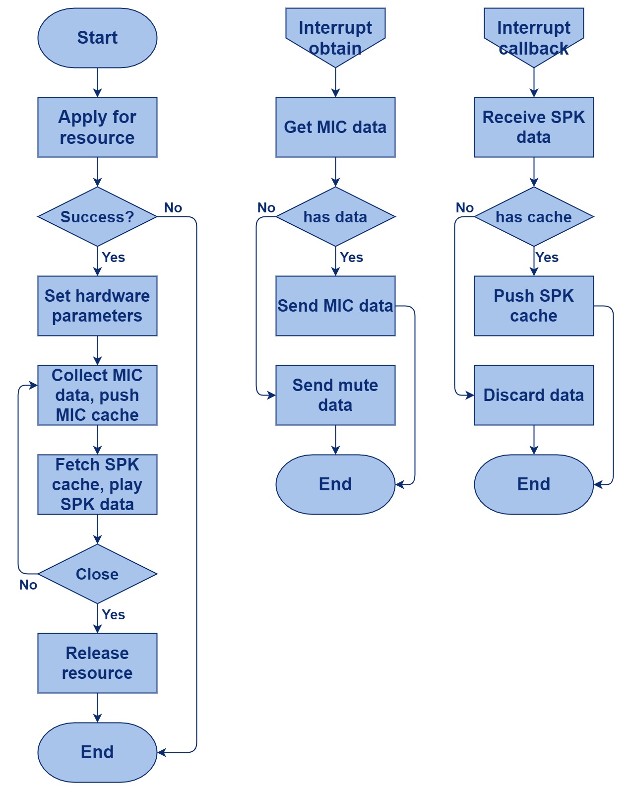
The following figure is a flow chart of voice data. The data is received through RF, then decoded and processed by speech algorithm, and finally sent to SPK, or the data from Mic is processed by voice algorithm, encoded and finally sent out through RF.
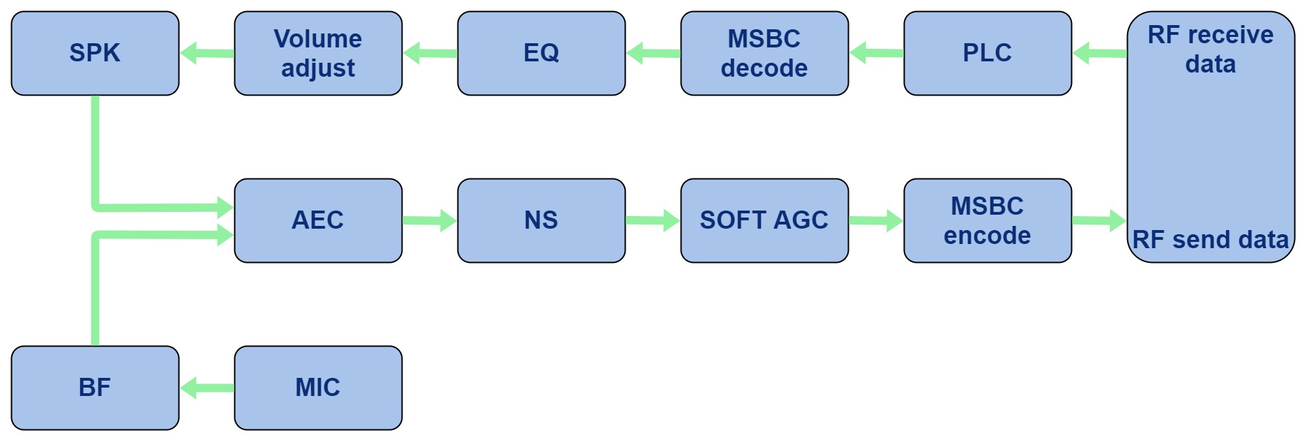
(3) Interface Description
MDI audSCO design
Macro definition:
The number of encoder buffer of the speaker:
#define TLKMDI_SCO_SPK_ENC_BUFF_NUMB 16
Encoder buffer size of the speaker:
#define TLKMDI_SCO_SPK_ENC_BUFF_SIZE 64
The number of encoder buffer of the mic:
#define TLKMDI_SCO_MIC_ENC_BUFF_NUMB 16
Encoder buffer size of the mic:
#define TLKMDI_SCO_MIC_ENC_BUFF_SIZE 64
The number of pcm buffer of the speaker:
#define TLKMDI_SCO_SPK_PCM_BUFF_SIZE 240
The number of pcm buffer of the mic:
#define TLKMDI_SCO_MIC_PCM_BUFF_SIZE 240
Buffer for noise suppression algorithms:
#define TLKMDI_SCO_SPEEX_NS_SIZE 9188
The ending marker for noise suppression algorithm:
#define TLKMDI_SCO_SPEEX_NS_OFFS 0
Buffer size for the SCO auto gain algorithm (requires data collection):
#define TLKMDI_SCO_AGC_ST_SIZE 1024
Data buffer size for auto gain:
#define TLKMDI_SCO_AGC_ST_OFFS (TLKMDI_SCO_SPEEX_NS_OFFS+TLKMDI_SCO_SPEEX_NS_SIZE)
Buffer required for voice processing:
#define TLKMDI_SCO_SPEEX_BUFFER_SIZE (TLKMDI_SCO_SPEEX_NS_SIZE+TLKMDI_SCO_AGC_ST_SIZE)
Buffer size for echo cancellation algorithm:
#define TLKMDI_SCO_AECM_ST_SIZE 10912
Ending mark:
#define TLKMDI_SCO_AECM_ST_OFFS 0
Echo cancelling data buffer:
#define TLKMDI_SCO_AECM_BUFFER_SIZE (TLKMDI_SCO_AECM_ST_SIZE)
CVSD parameter setting:
#define TLKMDI_SCO_CVSD_PARAM_SIZE TLKALG_CVSD_PARAM_SIZE
CVSD cache size:
#define TLKMDI_SCO_CVSD_CACHE_SIZE TLKALG_CVSD_CACHE_SIZE
CVSD buffer size:
#define TLKMDI_SCO_CVSD_BUFFER_SIZE (TLKMDI_SCO_CVSD_PARAM_SIZE+TLKMDI_SCO_CVSD_CACHE_SIZE)
The mSBC compressed size:
#define TLKMDI_SCO_SBC_ENC_BUFF_SIZE 3368
Ending mark:
#define TLKMDI_SCO_SBC_ENC_BUFF_OFFS 0
The mSBC decompressed size:
#define TLKMDI_SCO_SBC_DEC_BUFF_SIZE 1248
Ending mark:
#define TLKMDI_SCO_SBC_DEC_BUFF_OFFS TLKMDI_SCO_SBC_ENC_BUFF_SIZE
The mSBC buffer size:
#define TLKMDI_SCO_SBC_BUFFER_SIZE (TLKMDI_SCO_SBC_ENC_BUFF_SIZE+TLKMDI_SCO_SBC_DEC_BUFF_SIZE)
The SCO temporary data buffer size:
#define TLKMDI_SCO_TEMP_BUFFER_SIZE 2048
The SCO compressor buffer size:
#define TLKMDI_SCO_ENCODE_BUFFER_SIZE (TLKMDI_SCO_SBC_BUFFER_SIZE)
The SCO cache buffer size:
#define TLKMDI_SCO_CACHE_BUFFER_SIZE (TLKMDI_SCO_SPK_ENC_BUFF_SIZETLKMDI_SCO_SPK_ENC_BUFF_NUMB\
 +TLKMDI_SCO_MIC_ENC_BUFF_SIZETLKMDI_SCO_MIC_ENC_BUFF_NUMB)
The ID of voice codec CVSD:
#define TLKMDI_SCO_CODEC_ID_CVSD 1
The ID of voice codec MSBC:
#define TLKMDI_SCO_CODEC_ID_MSBC 2
The volume step:
#define TLKMDI_SCO_VOLUME_STEP 6
The SCO packet loss detection:
#define TLKMDI_SCO_PACKET_LOSS_FLAG 1
The SCO lost test:
#define TLKMDI_SCO_SCO_LOSS_TEST 0
Disable PLC:
#define TLKMDI_SCO_PLC_ENABLE 0
Enable PLC:
#define TLKMDI_SCO_PLC_ENABLE1 1
Mono mode of voice:
#define CODEC_DAC_MONO_MODE 1
The number of SCO's GRAD:
#define TLKMDI_SCO_GRAD_NUMBER 12
The SCO GRAD volume:
#define TLKMDI_SCO_GRAD_VOLUME 1
Data structure:
Define the following data structure:
typedef struct{
        uint08 *pTempBuffer;
        uint08 *pAecmBuffer;
        uint08 *pSpeexBuffer;
        uint08 *pCacheBuffer;
        uint08 *pEncodeBuffer;
}tlkmdi_sco_buff_t;
- pTempBuffer: temporary data buffer
- pAecmBuffer: echo cancelling data buffer
- pSpeexBuffer: speech pre-processing buffer
- pCacheBuffer: cache buffer
- pEncodeBuffer: encoder buffer
Define the following data structure:
typedef struct{
        uint08 numb;
        uint08 enable;
        uint16 handle;
        TlkMdiScoDecFunc dec_func;
        TlkMdiScoEncFunc enc_func;
        TlkMdiScoPlcFunc plc_func;
}tlkmdi_sco_ctrl_t;
- numb: number
- enable: whether to enable
- handle: Ctrl's identifier
- dec_func: decompression function
- enc_func: compression function
- plc_func: plc function
Global variable:
The header added in front of the decoder:
const unsigned char sTlkMdiScoMSBCSilencePkt[60]
Store the currently used SCO codec:
uint08 sTlkMdiScoCodec
SCO error index:
uint16 sTlkMdiScoErrIndex = 0
SCO error count:
uint16 sTlkMdiScoErrCount = 0
SCO mic mute index:
uint08 sTlkMdiMicMuteIndex
Callback function type definition:
Define SCO status callback function prototype:
typedef void(*TlkMdiScoStatusFunc)(uint16 handle, uint08 status)
Define Dec callback function prototype:
typedef int(*TlkMdiScoDecFunc)(uint08 *pSrc, uint16 srcLen, uint08 *pOut)
Define ENC callback function prototype:
typedef int(*TlkMdiScoEncFunc)(uint08 *pSrc, uint16 srcLen, uint08 *pOut)
Define PLC callback function prototype:
typedef int(*TlkMdiScoPlcFunc)(uint08 *pSrc, uint16 srcLen, uint08 *pOut)
Interface definition:
This interface has the following functions:
int tlkmdi_audsco_init(void)
a) Register the callback function of SCO speaker and mic
b) Register SCO status callback function
Is there any SCO currently in use:
bool tlkmdi_audsco_isBusy(void)
Get the SCO interval, which is used to calculate the timeout of the next timer:
uint tlkmdi_audsco_intval(void)
Switch between SCO enable and disable:
bool tlkmdi_audsco_switch(uint16 handle, uint08 status)
The SCO's mic and speaker handling functions:
bool tlkmdi_audsco_handler(void)
Get Codec id:
uint tlkmdi_sco_getCodec(void)
Set Codec:
void tlkmdi_sco_setCodec(uint08 codec)
AudHfp Design and Implementation
(1) Module Introduction
TBD
(2) Run Process
TBD
(3) Interface Description
MDI AudHF design
Data structure:
Define control data for audag:
typedef struct{
        uint08 enable;
}tlkmdi_audag_ctrl_t
Interface definition:
The following three interfaces are not supported:
int tlkmdi_audag_init(void)
int tlkmdi_audag_start(uint16 handle)
int tlkmdi_audag_close(uint16 handle)
Determine if audag has been turned on:
bool tlkmdi_audag_isBusy(void)
Query audag interval:
uint tlkmdi_audag_intval(void)
Is the switch audag status has been turned on:
bool tlkmdi_audag_switch(uint16 handle, uint08 status)
Determine if audag is enabled:
bool tlkmdi_audag_handler(void)
AudMp3 Design and Implementation
(1) Module Introduction
The MP3 module mainly includes two parts: the first part is to provide the interface for processing MP3 data, the Play, Tone, and SRC modules of the MDI layer call the MP3 interface to play music; the second part is the use strategy of MP3, including MP3 information loading, MP3 decoder configuration, MP3 file loading, MP3 data decoding into pcm data, MP3 playback mode design and song information update and acquisition, etc.
(2) Operation Process
Only provide interface, no process.
(3) Interface Description
MDI audMp3 design
Macro definition:
Define PCM size:
#define TLKMDI_MP3_PCM_SIZE (1152*4)
Define Dir size:
#define TLKMDI_MP3_DIR_SIZE 20
Define MP3 name length:
#define TLKMDI_MP3_NAME_SIZE TLKMDI_CFG_MP3_NAME_SIZE
Define MP3 path size:
#define TLKMDI_MP3_PATH_SIZE (TLKMDI_MP3_DIR_SIZE+TLKMDI_MP3_NAME_SIZE)
Define decoder parameter:
#define TLKMDI_MP3_DEC_PARAM_SIZE 6672
Define decoder cache0 size:
#define TLKMDI_MP3_DEC_CACHE0_SIZE 16240
Define decoder cache1 size:
#define TLKMDI_MP3_DEC_CACHE1_SIZE 4608
Define decoder cache offset address:
#define TLKMDI_MP3_DEC_CACHE1_OFFS TLKMDI_MP3_DEC_CACHE0_SIZE
Define decoder cache size:
#define TLKMDI_MP3_DEC_CACHE_SIZE (TLKMDI_MP3_DEC_CACHE0_SIZE+TLKMDI_MP3_DEC_CACHE1_SIZE)
Define decoder PCM size:
#define TLKMDI_MP3_DEC_PCM_SIZE (1152*8+4)
Define MP3 performance size:
#define TLKMDI_MP3_PERFORMER_SIZE 24
Define MP3 default interval:
#define TLKMDI_MP3_SAVE_INTERVAL 5000000
Define default timer:
#define TLKMDI_MP3_UPDATE_TIMER_DEF 5000000
Define maximum value of the timer:
#define TLKMDI_MP3_UPDATE_TIMER_MAX 20000000
Define minimum value of the timer:
#define TLKMDI_MP3_UPDATE_TIMER_MIN 1000000
Define the identifier of the file:
#define TLKMDI_MP3_FILE_INFO_SIGN 0x3A
Define the version of the file:
#define TLKMDI_MP3_FILE_INFO_VERS 0x02
Define the address of the file:
#define TLKMDI_MP3_FILE_INFO_ADDR TLK_CFG_FLASH_PLAY_INFO_ADDR
Define the size of the file:
#define TLKMDI_MP3_FILE_INFO_SIZE (4+TLKMDI_MP3_NAME_SIZE)
Define the identifier of the file list:
#define TLKMDI_MP3_FILE_LIST_SIGN 0x3C3C
Define the version of the file list:
#define TLKMDI_MP3_FILE_LIST_VERS 0x01
Define the size of the file list:
#define TLKMDI_MP3_FILE_LIST_SIZE (4+TLKMDI_MP3_NAME_SIZE)
Define the address of the file list:
#define TLKMDI_MP3_FILE_LIST_ADDR TLK_CFG_FLASH_PLAY_LIST_ADDR
Define the length of the file list:
#define TLKMDI_MP3_FILE_LIST_LENS TLK_CFG_FLASH_PLAY_LIST_LENS
Most file list:
#define TLKMDI_MP3_FILE_LIST_MAX ((TLK_CFG_FLASH_PLAY_LIST_LENS-16)/TLKMDI_MP3_FILE_LIST_SIZE)
The head length of MP3 label:
#define TLKMDI_MP3_LABEL_HLEN 10
The MP3 file cache size:
#define TLKMDI_MP3_FILE_CACHE_SIZE 2048
The 1/2 of the mp3 file cache, used for strategy judgement:
#define TLKMDI_MP3_FILE_CACHE_HALF 1024
The 1/3 of the mp3 file cache, used for strategy judgment:
#define TLKMDI_MP3_FILE_CACHE_THIRD 680
The cache size of MP3 info:
#define TLKMDI_MP3_INFO_CACHE_SIZE (MINIMP3_MAX_SAMPLES_PER_FRAME)
Data structure:
Define the playback mode:
typedef enum{
        TLKMDI_MP3_PALY_MODE_ORDER = 0,
        TLKMDI_MP3_PALY_MODE_LOOP,
        TLKMDI_MP3_PALY_MODE_RANDOM,
        TLKMDI_MP3_PALY_MODE_MAX,
}TLKMDI_MP3_PALY_MODE_ENUM;
- TLKMDI_MP3_PALY_MODE_ORDER: sequential play
- TLKMDI_MP3_PALY_MODE_LOOP: loop play
- TLKMDI_MP3_PALY_MODE_RANDOM: random play
Define the data compression format for MP3:
typedef enum{
        TLKMDI_MP3_MPEG_TYPE_2P5 = 0,
        TLKMDI_MP3_MPEG_TYPE_RESERVE,
        TLKMDI_MP3_MPEG_TYPE_2,
        TLKMDI_MP3_MPEG_TYPE_1,
}TLKMDI_MP3_MPEG_TYPE_ENUM;
- TLKMDI_MP3_MPEG_TYPE_2P5: Mpeg 2P5 type for MP3
- TLKMDI_MP3_MPEG_TYPE_2: Mpeg 2 type for MP3
- TLKMDI_MP3_MPEG_TYPE_1: Mpeg 1 type for MP3
Define the main data format for the stream of MP3:
typedef enum{
        TLKMDI_MP3_LAYER_TYPE_RESERVE = 0,
        TLKMDI_MP3_LAYER_TYPE_3,
        TLKMDI_MP3_LAYER_TYPE_2,
        TLKMDI_MP3_LAYER_TYPE_1,
}TLKMDI_MP3_LAYER_TYPE_ENUM;
- TLKMDI_MP3_LAYER_TYPE_3: the current mainstream format is layer 3
- TLKMDI_MP3_LAYER_TYPE_2: streaming data format of layer2
- TLKMDI_MP3_LAYER_TYPE_1: streaming data format of layer1
Define the status of MP3:
typedef enum{
        TLKMDI_MP3_STATUS_IDLE = 0,
        TLKMDI_MP3_STATUS_WAIT,
        TLKMDI_MP3_STATUS_DONE,
        TLKMDI_MP3_STATUS_PLAY,
}TLKMDI_MP3_STATUS_ENUM;
- TLKMDI_MP3_STATUS_WAIT: waiting status
- TLKMDI_MP3_STATUS_DONE: status of completion
- TLKMDI_MP3_STATUS_PLAY: play status
Define the following data structure:
typedef struct{
        uint32 playLens;
        uint08 fileName[TLKMDI_MP3_NAME_SIZE];
}tlkmdi_mp3_fsave_t;
- playLens: length that can be played
- fileName: file name array
Define the following data structure:
typedef struct{
        uint32 count;
        uint08 vers;
        uint08 size;
        uint16 sign;
}tlkmdi_mp3_flist_t;
- count: MP3 file list length
- vers: MP3 file version
- size: single song size
- sign: marker of MP3 flash
Define the following data structure:
typedef struct{
        uint08 playMode;
        uint08 reserve0;
        uint16 curIndex;
        uint32 playLens;
        uint32 cacheLens;
        uint32 cacheOffs;
}tlkmdi_mp3_fplay_t;
- playMode: set play mode
- curIndex: current song index
- playLens: total play time
- cacheLens: cache size
- cacheOffs: cache offset
Define the following data structure:
typedef struct{
        uint32 fileSize;
        uint32 headLens;
        uint32 duration;
        uint08 channels;
        uint08 reserve0;
        uint16 sampleRate;
        uint08 performer[TLKMDI_MP3_PERFORMER_SIZE];
}tlkmdi_mp3_finfo_t;
- fileSize: file size
- headLens: file head length
- duration: the duration of the song
- channels: channel for song data
- sampleRate: song data sample rate
- performerperformer: singer information
Define the following data structure:
typedef struct{
        uint08 playMode;
        uint08 isUpdate;
        uint16 playIndex;
        uint16 fileCount;
        tlkapi_save_ctrl_t save;
        tlkmdi_mp3_fsave_t fsave;
        tlkmdi_mp3_fplay_t fplay;
        tlkmdi_mp3_finfo_t finfo;
}tlkmdi_mp3_ctrl_t;
- playMode: play mode
- isUpdate: have the songs been updated
- playIndex: index of playing songs
- fileCount: number of songs
- save: file control
- fsave: file storage
- fplay: file play
- finfo: file information
Global variable:
Store the current MP3 status:
uint08 gTlkMdiMp3Status = 0;
Used as the buffer for decode PCM data:
sint16 *spTlkMdiMp3DecodeTempBuff = NULL
Used as the temporary buffer for file information:
uint08 *spTlkMdiMp3FileInfoTempBuff = NULL
Used as data buffer for MP3 playing duration:
uint08 *spTlkMdiMp3DurationTempBuff = NULL
Interface definition:
This interface has the following functions:
int tlkmdi_mp3_init(void)
a) Determine whether each data buffer is emptied
b) Initialize control variable
c) Initialize memory
d) load file
Determine whether the current MP3 has been enabled:
bool tlkmdi_mp3_isEnable(void)
This interface has the following functions:
bool tlkmdi_mp3_enable(bool enable)
a) Reallocate data buffer
b) Start flash of Mp3 file
c) Initialize file information
d) Initialize mp3 decoder
Check whether all music has been played:
bool tlkmdi_mp3_indexIsOver(void)
Specify to play a certain music by index:
void tlkmdi_mp3_setPlayIndex(uint playIndex)
Get the index of the current music:
uint tlkmdi_mp3_getPlayIndex(void)
Get how many music there are:
uint tlkmdi_mp3_getPlayCount(void)
Get the index of the randomly played music:
uint tlkmdi_mp3_getRandIndex(void)
Get the index of the next song of the current music:
uint tlkmdi_mp3_getNextIndex(void)
Get the index of the previous song of the current music:
uint tlkmdi_mp3_getPrevIndex(void)
Get the file size of the music:
uint32 tlkmdi_mp3_getFileSize(void)
Get music length:
uint32 tlkmdi_mp3_getPlayLens(void)
Get the duration of the music:
uint32 tlkmdi_mp3_getDuration(void)
Get the music progress bar:
uint16 tlkmdi_mp3_getProgress(void)
Get the file name of the music:
uint08 *tlkmdi_mp3_getFileName(uint08 *pLength)
Get information about the singer of the song:
uint08 *tlkmdi_mp3_getSinger(uint08 *pLength)
Get the play mode of a song:
uint08 tlkmdi_mp3_getPlayMode(void)
Set the play mode of a song:
void tlkmdi_mp3_setPlayMode(uint08 mode)
Get the sample rate of a song:
uint16 tlkmdi_mp3_getSampleRate(void)
Get the channel of music:
uint08 tlkmdi_mp3_getChannels(void)
Clear pcm data:
void tlkmdi_mp3_clearPcmData(void)
Get the number of fifos that can be used to store the pcm buffer:
int tlkmdi_mp3_getPcmIdleLen(void)
Get the length of pcm data:
int tlkmdi_mp3_getPcmDataLen(void)
Add pcm data buffer to fifo:
void tlkmdi_mp3_addPcmData(uint08 *pData, uint16 dataLen)
Get pcm data buffer from fifo:
int tlkmdi_mp3_getPcmData(uint08 *pBuffer, uint16 buffLen)
Get MP3 file information:
tlkmdi_mp3_finfo_t *tlkmdi_mp3_getInfo(void)
Determine whether the current MP3 is over:
bool tlkmdi_mp3_isOver(void)
Start playing the specified music:
bool tlkmdi_mp3_play(uint16 index)
Prepare the decoder, clear the buffer, and prepare for streaming data:
bool tlkmdi_mp3_start(uint08 *pFilePath, uint32 fileOffset)
Close MP3:
void tlkmdi_mp3_close(void)
Decode mp3 data from flash into pcm data and put it into fifo:
int tlkmdi_mp3_decode(void)
Load file:
int tlkmdi_mp3_loadFile(bool isForce)
Determine if it is an MP3 file:
bool tlkmid_mp3_isMp3File(uint08 *pPath, uint08 lens)
Find file list:
int tlkmdi_mp3_scanFileList(void)
Find file path:
int tlkmdi_mp3_findFilePath(uint08 *pBuff, uint16 buffLen, bool addRoot)
Find file name:
int tlkmdi_mp3_findFileName(uint08 *pBuff, uint16 index)
Determine MP3 song update:
bool tlkmdi_mp3_isUpdate(void)
Determine if an update is required:
bool tlkmdi_mp3_needUpdate(void)
Start update:
void tlkmdi_mp3_startUpdate(void)
Enable update:
void tlkmdi_mp3_updateEnable(bool enable)
Update the name of the play song:
void tlkmdi_mp3_updatePlayName(uint08 *pFName, bool isForce)
Update the length of the song:
void tlkmdi_mp3_updatePlayLens(uint32 playLen, bool isForce)
AudSrc Design and Implementation
(1) Module Introduction
This module provides MMI to use the A2DP Source function interface, through this function module, the MP3 audio data stored in the Flash is obtained for Encode, and then the compressed A2DP data is sent out through Bluetooth.
(2) Operation Process
The following figure is the music data stream of A2DP SRC, as shown in the figure below.
The following figure is divided into two parts, Host and Controller. The data stream is from top to bottom. UL is a part of the upper layer Audio, the data is taken out from the storage, compressed by A2DP's Encoder, added with headers of each level, and then sent to BTC through HCI. After the BTC is added with the header, it is sent to the A2DP Sink device through RF.

The following figure is the code flow chart. First, switch the A2DP state to the Stream state, then start to configure the A2DP encoder and Audio path, configure the parameters required to obtain MP3 audio files, and the buffer required in each process. finally, the MP3 data is taken out from the Flash, and decoded into a PCM data stream, which is then encoded by the A2DP encoder and sent out through Bluetooth.
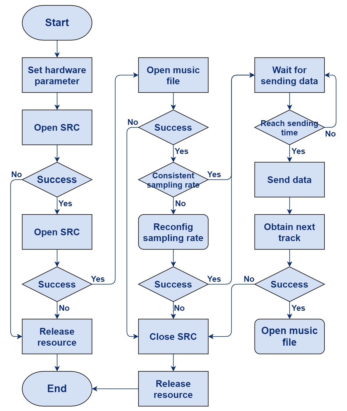
The following is the code flow sequence diagram.

(3) Interface Description
MDI audSrc design
Macro definition:
Length of SRC packet:
#define TLKMDI_SRC_PKT_BUFF_SIZE 680
Compressor buffer size:
#define TLKMDI_SRC_SBC_ENC_BUFF_SIZE 3368
Number of SRC frame data:
#define TLKMDI_SRC_FRAME_NUMB 7
Timeout for SRC reconfig:
#define TLKMDI_SRC_WAIT_RECFG_TIMEOUT 3000000
Data structure:
Define the following data structure:
typedef struct{
        uint08 runing;
        uint08 enable;
        uint16 handle;
        uint32 refTime;
        uint32 lagTime;
        uint08 sndFrame;
        uint08 resv0001;
        uint16 seqNumber;
        uint32 unitTime;
        uint32 timeStamp;
        uint08 mp3State;
        uint08 waitStart;
        uint16 playIndex;
        uint32 waitTimer;
}tlkmdi_audsrc_ctrl_t;
- runing: is it running
- enable: whether to enable
- handle: marker
- refTime: reference clock
- lagTime: data play duration
- sndFrame: number of compressed data frames
- seqNumber: encoding of data frames
- unitTime: continuous play time of compressed data at one time
- timestamp: timestamp of data
- mp3State: MP3 state
- waitStart: mark waiting to start
- playIndex: played index
- waitTimer: timer to control action
Data interface:
Initialize sTlkMdiSrcCtrl, register callback function:
int tlkmdi_audsrc_init(void)
A2dp start music data stream:
int tlkmdi_audsrc_start(uint16 handle, uint32 param)
A2dp stop music data stream:
int tlkmdi_audsrc_close(uint16 handle)
Switching A2dp status:
bool tlkmdi_audsrc_switch(uint16 handle, uint08 status)
Play the next music:
bool tlkmdi_audsrc_toNext(void)
Play the previous music:
bool tlkmdi_audsrc_toPrev(void)
Query whether it is currently in use:
bool tlkmdi_audsrc_isBusy(void)
Get timer:
uint tlkmdi_audsrc_intval(void)
Process MP3 data:
bool tlkmdi_audsrc_handler(void)
AudSnk Design and Implementation
(1) Module Introduction
This module provides the interface for the MMI layer to use the A2DP SNK functions, which include receiving Audio data, A2DP decoding the data and sending the decoded data to audio for processing.
(2) Operation Process
The following is the data stream diagram of A2DP Sink receiving data. The data is received from RF, processed at BTC and sent to Host, and unpacked after Host receives the data, finally decoded by the A2DP Decoder and sent to Audio.
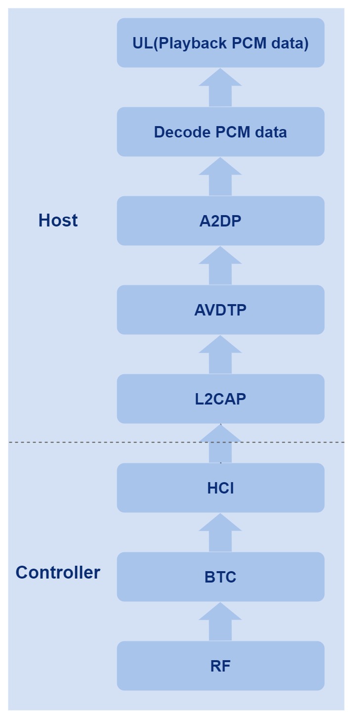
The following figure is the code flow chart. First, switch the A2DP state to the Stream state through the start process, and then start to configure the audio path driver and A2DP decoder in the Stream state, and configure the buffer required by the audio data in each process, and finally start process music data and send the processed music data to Speaker.
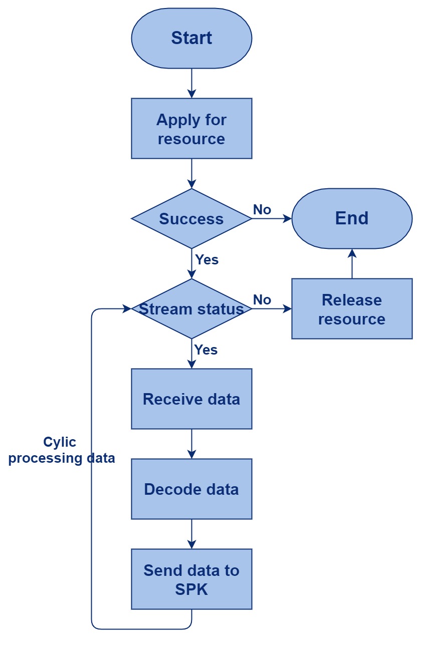
The process sub-sequence diagram is as follows.

(3) Interface Description
MDI audSnk design
Macro definition:
Defines decompression temporary buffer size:
#define TLKMDI_SNK_DEC_TEMP_SIZE 4096
Define the buffer size for Raw data:
#define TLKMDI_SNK_RAW_RCV_BUFF_SIZE 10560
Define the buffer size for decompressing SBC:
#define TLKMDI_SNK_SBC_DEC_BUFF_SIZE 1248
Define the sample rate:
#define TLKMDI_SNK_SBC_FREQ_MASK      0xC0
#define TLKMDI_SNK_SBC_FREQ_16000     0x00
#define TLKMDI_SNK_SBC_FREQ_32000     0x40
#define TLKMDI_SNK_SBC_FREQ_44100     0x80
#define TLKMDI_SNK_SBC_FREQ_48000     0xC0
Define the number of blocks:
#define TLKMDI_SNK_SBC_BLOCK_MASK     0x30
#define TLKMDI_SNK_SBC_BLOCK_4        0x00
#define TLKMDI_SNK_SBC_BLOCK_8        0x10
#define TLKMDI_SNK_SBC_BLOCK_12       0x20
#define TLKMDI_SNK_SBC_BLOCK_16       0x30
Define the number of subbands:
#define TLKMDI_SNK_SBC_SUBBAND_MASK     0x01
#define TLKMDI_SNK_SBC_SUBBAND_4        0x00
#define TLKMDI_SNK_SBC_SUBBAND_8        0x10
Define the audio mode, whether it is mono, dual or stereo surround, etc.:
#define TLKMDI_SNK_SBC_TYPE_MASK            0x0C
#define TLKMDI_SNK_SBC_TYPE_MONO            0x00
#define TLKMDI_SNK_SBC_TYPE_DUAL_MODE       0x04
#define TLKMDI_SNK_SBC_TYPE_STEREO          0x08
#define TLKMDI_SNK_SBC_TYPE_JOINT_STEREO    0x0C
Decompressed fifo size:
#define TLKMDI_SNK_ENC_FIFO_MIN_SIZE 4096
Data structure:
typedef struct{
        uint08 enable;
        uint08 firstInit;
        uint16 handle;
        uint16 frameSize;
        uint16 sampleRate;
        uint16 frameSample;
        uint32 encParma;
        tlkmdi_snk_decFunc decFunc;
}tlkmdi_audsnk_ctrl_t;
- enable: enable a2dp snk
- firstInit: initialisation marker
- handle: mark audio snk
- frameSize: data frame size
- sampleRate: sample rate
- frameSample: sampling number of data frames
- encParma: compression parameter
- decFunc: decompression function
Callback function type definition:
Define the decompression data function prototype:
typedef int(*tlkmdi_snk_decFunc)(uint08 *pData, int len, uint08 *pOut)
Interface definition:
This interface has the following functions:
int tlkmdi_audsnk_init(void)
a) Initialize FIFO
b) Initialize sTlkMdiSnkCtrl
b) Register callback function
Start playing music:
int tlkmdi_audsnk_start(uint16 handle, uint32 param)
Stop playing music:
int tlkmdi_audsnk_close(uint16 handle)
Switch A2DP sink state, switch between enable and disable:
bool tlkmdi_audsnk_switch(uint16 handle, uint08 status)
Play the next music:
bool tlkmdi_audsnk_toNext(void)
Play the previous music:
bool tlkmdi_audsnk_toPrev(void)
Query whether the current A2DP sink is enabled:
bool tlkmdi_audsnk_isBusy(void)
Get interval:
uint tlkmdi_audsnk_intval(void)
Process the PCM data processed by the sink:
bool tlkmdi_audsnk_handler(void)
Add pcm data to fifo:
void tlkmdi_snk_addEncFrame(uint08 *pData, uint16 dataLen)
Set buffer to fifo:
int tlkmdi_snk_setBuffer(uint08 *pBuffer, uint32 buffLen)
Get timer value:
uint tlkmdi_snk_getTimer(void)
AudPlay Design and Implementation
(1) Module Introduction
This module mainly provides MMI Audio with an interface for local music play, and some logical processing, including how to start local music play, how to call MP3 and configure the decoder, how to set Audio related channels and how to handle music data.
(2) Operation Process

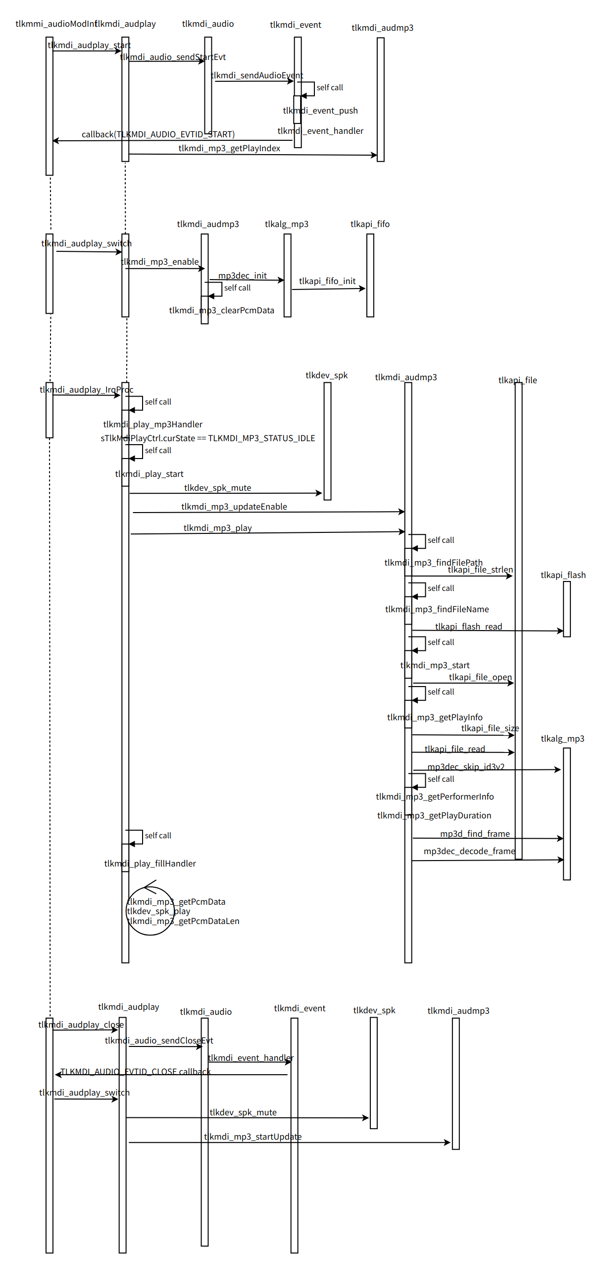
(3) Interface Description
MDI audPlay design
Macro definition:
Define the step of volume change:
#define TLKMDI_PLAY_VOLUME_STEP 3
Data structure:
typedef struct{
        uint08 runing;
        uint08 status;
        uint08 enable;
        uint08 curState;
        uint16 playIndex;
        uint16 sampleRate;
}tlkmdi_play_ctrl_t;
- runing: whether play has been executed
- Status: connection state
- enable: enable MP3 play
- curState: MP3 state
- playIndex: index of playing music
- sampleRate: sample rate of audio data
Interface definition:
This interface has the following functions:
int tlkmdi_audplay_init(void)
a) Initialize Play's control data
b) Initialize the song index for music play
Start playing music:
int tlkmdi_audplay_start(uint16 handle, uint32 param)
Stop playing music:
int tlkmdi_audplay_close(uint16 handle)
Play the next music:
bool tlkmdi_audplay_toNext(void)
Play the previous music:
bool tlkmdi_audplay_toPrev(void)
This interface has the following functions:
bool tlkmdi_audplay_switch(uint16 handle, uint08 status)
a) Update music state
b) Get MP3 data to update Play control data
c) Initialize codec
Query if it is currently playing:
bool tlkmdi_audplay_isBusy(void)
Query the play interval to update the timer:
uint tlkmdi_audplay_intval(void)
Player's processing function:
bool tlkmdi_audplay_IrqProc(void)
Configure current state and play index:
void tlkmdi_play_setParam(uint16 fileIndex)
AudTone Design and Implementation
(1) Module Introduction
This module mainly provides MMI Audio with a Tone interface and some logic processing, including how to start Tone play, how to call MP3 and configure the decoder, how to set the Audio channel and how to process the Tone data.
(2) Operation Process
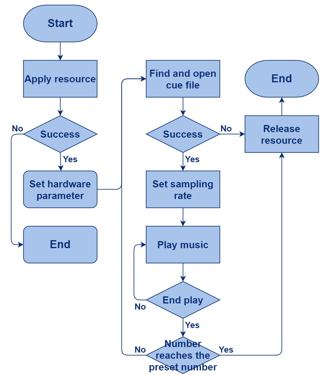
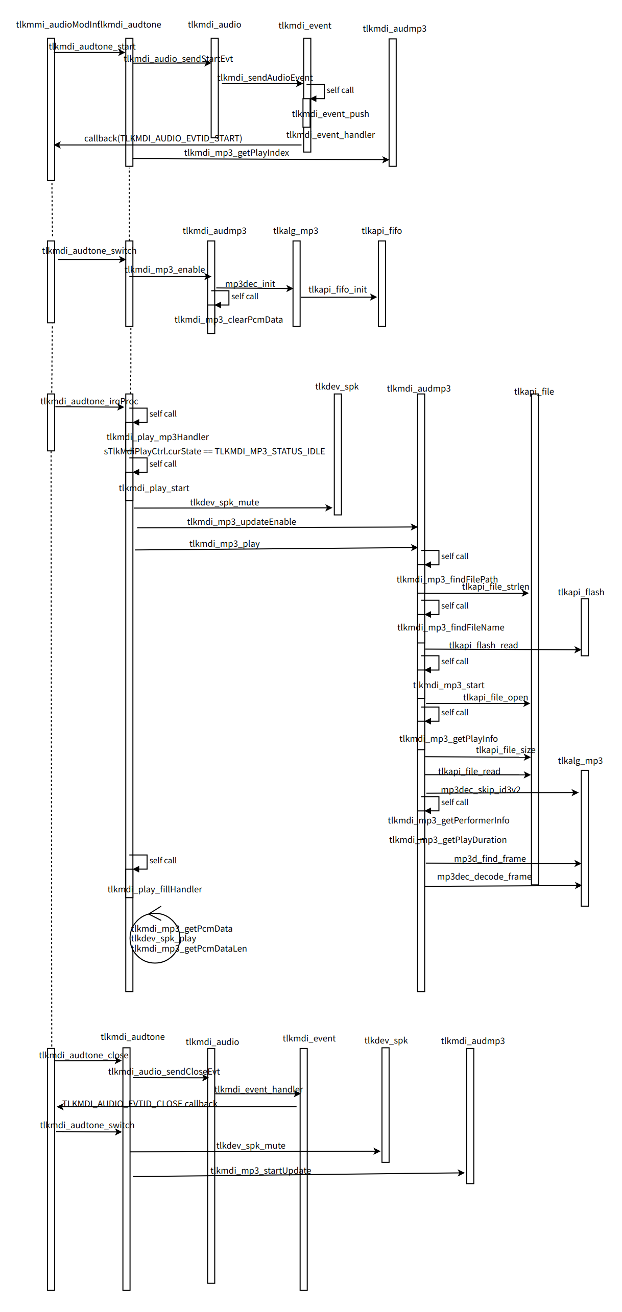
(3) Interface Description
MDI audTone design
Data structure:
typedef struct{
        uint08 runing;
        uint08 enable;
        uint08 curState;
        uint08 playNumb;
        uint08 playCount;
        uint16 playIndex;
}tlkmdi_tone_ctrl_t;
- runing: whether to run
- enable: whether to enable
- curState: current state
- playNumb: number of already played
- playCount: total number of plays
- playIndex: currently playing index
typedef enum{
        TLKMDI_TONE_TYPE_CONNECT = 0x0,
        TLKMDI_TONE_TYPE_DISCONN,
        TLKMDI_TONE_TYPE_CALL_RING,
        TLKMDI_TONE_TYPE_BI,
        TLKMDI_TONE_TYPE_BO,
        TLKMDI_TONE_TYPE_DING,
        TLKMDI_TONE_TYPE_DING_DING,
        TLKMDI_TONE_TYPE_MAX
}TLKMDI_TONE_TYPE_ENUM;
- TLKMDI_TONE_TYPE_CONNECT: connection state
- TLKMDI_TONE_TYPE_CONNECT: disconnected state
- TLKMDI_TONE_TYPE_CALL_RING: phone ringing
- TLKMDI_TONE_TYPE_BI,TLKMDI_TONE_TYPE_BO,TLKMDI_TONE_TYPE_DING, TLKMDI_TONE_TYPE_DING_DING: beep type
Interface definition:
This interface has the following functions:
int tlkmdi_audtone_init(void)
a) Initialize sTlkMdiToneCtrl
b) Get the index of tone played and the total number of Tone played
Configure the play data of sTlkMdiToneCtrl:
int tlkmdi_audtone_start(uint16 handle, uint32 param)
Switch the state of Tone to close:
int tlkmdi_audtone_close(uint16 handle)
Query whether the current Tone is in use:
bool tlkmdi_audtone_isBusy(void)
According to the current music data, return the timer's timeout to ensure the continuous music data:
uint tlkmdi_audtone_intval(void)
This interface has the following functions:
bool tlkmdi_audtone_switch(uint16 handle, uint08 status)
a) Enable MP3
b) Initialize codec and configure the codec sample rate
c) Configure Tone's control data
Tone's process and data processing:
bool tlkmdi_audtone_IrqProc(void)
This interface has the following functions:
bool tlkmdi_tone_start(uint16 index)
a) Take the file to be played from flash
b) Call the start of MP3, configure the information of the file to be played and clear the fifo
c) Configure decoder
Close MP3:
void tlkmdi_tone_close(void)
Set the index of the played Tone and the total number of Tones:
void tlkmdi_tone_setParam(uint16 playIndex, uint08 playCount)
Phone Module Design
HFP Design and Implementation
(1) Module Introduction
This module mainly provides phone-related interfaces, such as dialing, answering, and hanging up calls, etc. It also provides PBAP interfaces. The difference with the function of the AudHF module is that AudHF is only responsible for the Audio-related part, not the phone-related functions.
(2) Status Conversion
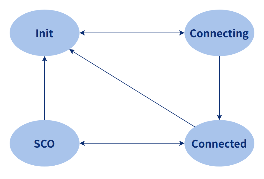
(3) Operation Process
The following figure is the schematic diagram of the HFP HF dialing process:
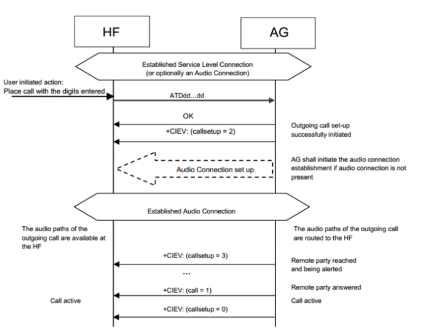
The following figure is the flow chart of making a call:
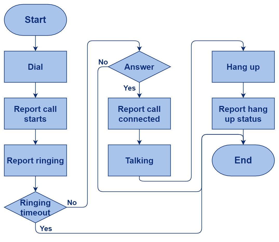
The following figure is the schematic diagram of the incoming call:
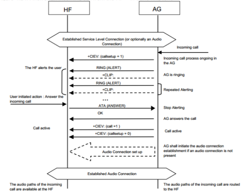
The following figure is the flow chart of incoming call answering:

The following figure is the code flow sequence diagram for HF to make and hang up calls:
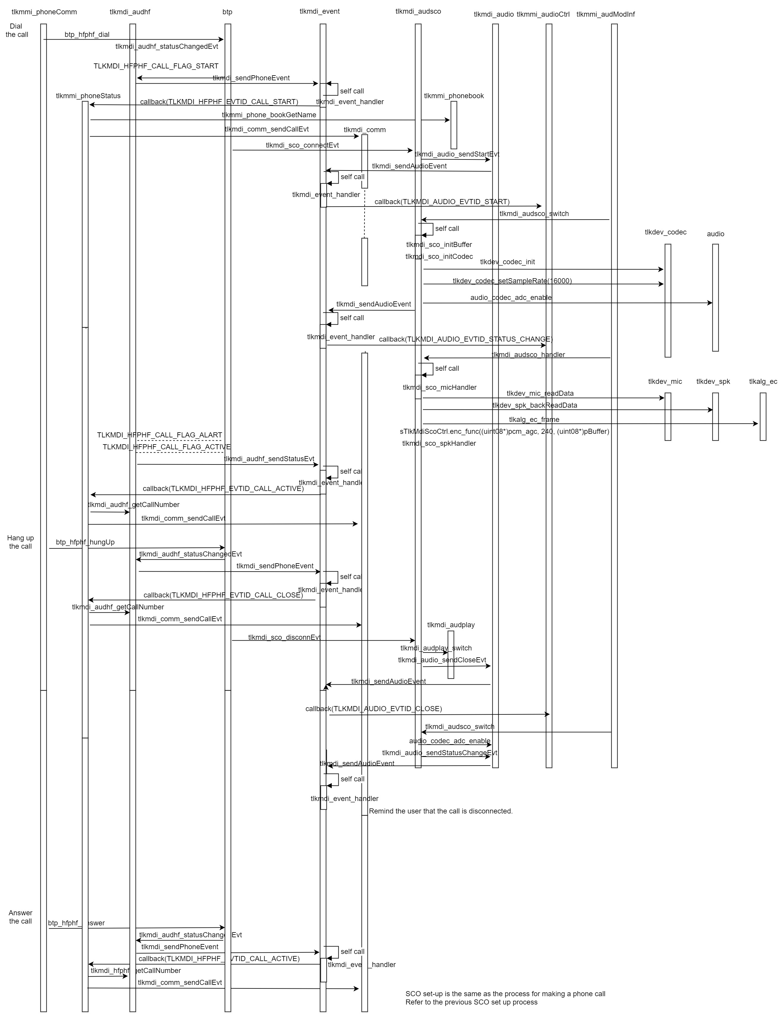
(4) Interface Description
MDI HF design
Macro definition:
HF timeout duration:
#define TLKMDI_AUDHF_TIMEOUT 100000
Call wait timeout duration:
#define TLKMDI_AUDHF_CALL_WAIT_TIMEOUT (3000000/TLKMDI_AUDHF_TIMEOUT)
Call phone number length:
#define TLKMDI_HFPHF_NUMBER_MAX_LEN 64
Data structure:
Define the following data structure:
typedef enum{
        TLKMDI_HFPHF_EVTID_NONE = 0,
        TLKMDI_HFPHF_EVTID_CALL_CLOSE,
        TLKMDI_HFPHF_EVTID_CALL_START,
        TLKMDI_HFPHF_EVTID_CALL_ALART,
        TLKMDI_HFPHF_EVTID_CALL_ACTIVE,
}TLKMDI_HFPHF_EVTID_ENUM;
- TLKMDI_HFPHF_EVTID_CALL_CLOSE: phone hung up
- TLKMDI_HFPHF_EVTID_CALL_START: start calling
- TLKMDI_HFPHF_EVTID_CALL_ALART: phone ringing
- TLKMDI_HFPHF_EVTID_CALL_ACTIVE: phone connected
Define the following data structure:
typedef enum{
        TLKMDI_HFPHF_CALL_DIR_NONE = 0,
        TLKMDI_HFPHF_CALL_DIR_INCOMING,
        TLKMDI_HFPHF_CALL_DIR_OUTGOING,
}TLKMDI_HFPHF_CALL_DIR_ENUM;
- TLKMDI_HFPHF_CALL_DIR_INCOMING: incoming calls
- TLKMDI_HFPHF_CALL_DIR_OUTGOING: outgoing calls
Define the following data structure:
typedef enum{
        TLKMDI_HFPHF_CALL_STATUS_NONE = 0,
        TLKMDI_HFPHF_CALL_STATUS_START,
        TLKMDI_HFPHF_CALL_STATUS_ALART,
        TLKMDI_HFPHF_CALL_STATUS_ACTIVE,
}TLKMDI_HFPHF_CALL_STATUS_ENUM;
- TLKMDI_HFPHF_CALL_STATUS_START: start calling
- TLKMDI_HFPHF_CALL_STATUS_ALART: waiting to be connected
- TLKMDI_HFPHF_CALL_STATUS_ACTIVE: connect the phone
Define the following data structure:
typedef enum{
        TLKMDI_HFPHF_CALL_BUSY_NONE = 0x00,
        TLKMDI_HFPHF_CALL_BUSY_WAIT_NUMBER = 0x01,
}TLKMDI_HFPHF_CALL_BUSYS_ENUM;
TLKMDI_HFPHF_CALL_BUSY_WAIT_NUMBER: Mark the need to re-execute the action to get the phone number.
Define the following data structure:
typedef enum{
        TLKMDI_HFPHF_CALL_FLAG_NONE   = 0x00,
        TLKMDI_HFPHF_CALL_FLAG_CLOSE  = 0x01,
        TLKMDI_HFPHF_CALL_FLAG_START  = 0x02,
        TLKMDI_HFPHF_CALL_FLAG_ALART  = 0x04,
        TLKMDI_HFPHF_CALL_FLAG_ACTIVE = 0x08,
        TLKMDI_HFPHF_CALL_FLAG_NUMBER = 0x10,
        TLKMDI_HFPHF_CALL_FLAG_REPORT_START  = 0x20,
        TLKMDI_HFPHF_CALL_FLAG_REPORT_ACTIVE = 0x40,
        TLKMDI_HFPHF_CALL_FLAG_REPORT_CLOSE  = 0x80,
        TLKMDI_HFPHF_CALL_FLAG_STATUS_MASK = TLKMDI_HFPHF_CALL_FLAG_START | TLKMDI_HFPHF_CALL_FLAG_ALART
                | TLKMDI_HFPHF_CALL_FLAG_ACTIVE | TLKMDI_HFPHF_CALL_FLAG_CLOSE,
        TLKMDI_HFPHF_CALL_FLAG_REPORT_MASK = TLKMDI_HFPHF_CALL_FLAG_REPORT_START | TLKMDI_HFPHF_CALL_FLAG_REPORT_ACTIVE
                | TLKMDI_HFPHF_CALL_FLAG_REPORT_CLOSE,
}TLKMDI_HFPHF_CALL_FLAGS_ENUM;
- TLKMDI_HFPHF_CALL_FLAG_CLOSE: mark Call Close event
- TLKMDI_HFPHF_CALL_FLAG_START: mark Call Start event
- TLKMDI_HFPHF_CALL_FLAG_ALART: mark Call Alart event
- TLKMDI_HFPHF_CALL_FLAG_ACTIVE: mark Active event
- TLKMDI_HFPHF_CALL_FLAG_NUMBER: mark phone number event
- TLKMDI_HFPHF_CALL_FLAG_REPORT_START: mark whether to report phone has started status
- TLKMDI_HFPHF_CALL_FLAG_REPORT_CLOSE: mark whether to report phone closed status
- TLKMDI_HFPHF_CALL_FLAG_REPORT_ACTIVE: mark whether to report phone activation status
- TLKMDI_HFPHF_CALL_FLAG_STATUS_MASK: status mask
- TLKMDI_HFPHF_CALL_FLAG_REPORT_MASK: mark whether to report the status mask
Define the following data structure:
typedef struct{
        uint08 status;
        uint16 handle;
        uint08 timeout;
        uint08 numbLen;
        uint08 callDir;
        uint08 callBusy;
        uint08 callFlag;
        uint08 reserved;
        uint16 callHandle;
        tlkapi_timer_t timer;
        uint08 number[TLKMDI_HFPHF_NUMBER_MAX_LEN];
}tlkmdi_audhf_ctrl_t;
- status: mark phone status
- handle: mark control block
- timeout: timeout duration
- numbLen: length of phone number
- callDir: phone call in/out
- callBusy: record the current action not executed in time
- callFlag: record the currently reported event
- callHandle: phone handle
- timer: control block timer
- number: phone number
Define the following data structure:
typedef struct{
        uint08 codec;
        uint16 handle;
}tlkmdi_audhf_codecEvt_t;
- Codec: SCO's codec
- handle: SCO's handle
Define the following data structure:
typedef struct{
        uint16 handle;
        uint08 callDir;
        uint08 numbLen;
}tlkmdi_audhf_statusEvt_t;
- handle: mark handle
- callDIr: phone call in/out
- numbLen: length of phone number
Interface definition:
Initialize timer, register callback function:
int tlkmdi_audhf_init(void)
int tlkmdi_audhf_start(uint16 handle)
int tlkmdi_audhf_close(uint16 handle)
Destroy the HF resource specified by handle:
void tlkmdi_audhf_destroy(uint16 aclHandle)
Query whether the current status is open:
bool tlkmdi_audhf_isBusy(void)
Get the interval of HF:
uint tlkmdi_audhf_intval(void)
Switch the state of HF, enable/disable:
bool tlkmdi_audhf_switch(uint16 handle, uint08 status)
Query whether Audio is in the OPEN state:
bool tlkmdi_audhf_handler(void)
Get phone number:
uint08 *tlkmdi_audhf_getCallNumber(void)
PBAP Design and Implementation
(1) Module Introduction
The PBAP module provides a functional interface for obtaining the phone book of the counterpart device. The link process is as follows, PCE is Client, PSE is Server, PBAP will be triggered by the application to execute after the ACL is established.
(2) Operation Process
PBAP link process.
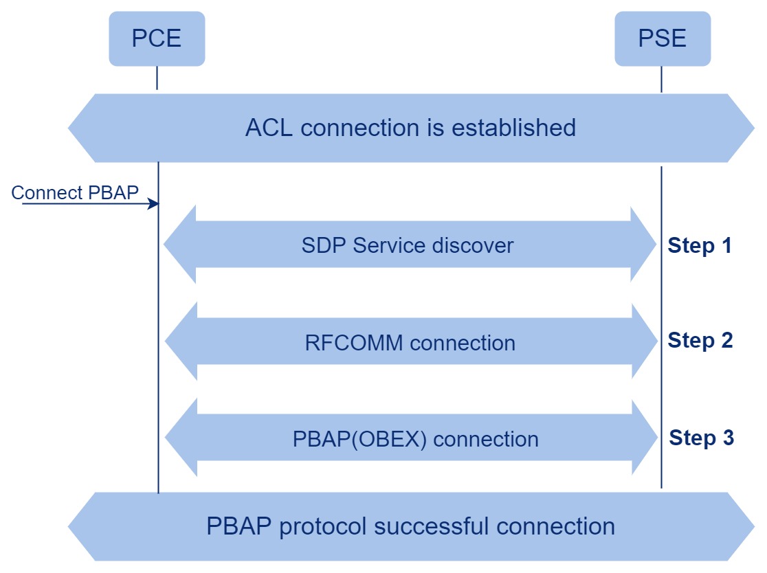
(3) Interface Description
TBD
Audio Volume Adjustment Process
At present, the volume of each audio business has been independently operated and does not affect each other.
