B80 BLE OTP SDK
SDK Overview
This SDK provides users with demos of self-timer based on B80 (TLSR820x and TLSR8373) chip development, as well as non-HID demos, on which customers can develop.
SDK File Structure
ble: BLE protocol related constants
Bluelight: Generated target files
lib: Protocol stack library file, available in 4 versions as follows.
-
liblib.a OTP, UUID16bit
-
liblib128.a OTP, UUID128bit
-
liblibFlash.a Flash, UUID16bit
-
liblibFlash128.a Flash, UUID128bit
proj: Driver source files
-
proj\common:Data structure related
-
proj\drivers:Peripheral drivers
-
proj\mcu:mcu driver
proj_lib: Third-party library files
vendor: Application related, user-written source code
-
vendor\blueLight\app_config.h:project related constant
-
vendor\blueLight\attributes.c:BLE attribute table definition
-
vendor\blueLight\attributes.h:BLE attribute table definition header file
-
vendor\blueLight\bluelight.h: BLE packet structure definition
-
vendor\blueLight\blueLight-128-uuid.h:Example of a BLE 128bit attribute table. Note that in order to keep the bin file to a minimum, liblib.a currently only supports 16bit UUIDs. To support 128bit attributes, please link liblib128.a file.
-
vendor\blueLight\emi.c:EMI test
-
vendor\blueLight\main.c:User logic code, initialization/main loop functions
project: The project is the project folder, where the .cproject, .project files are the corresponding project files, where the folders are the files generated by the compilation, for example, bluelight.bin and bluelight.lst will be generated inside the bluelight folder.
Brief steps for SDK development
Step 1 Implementation of the user_init function: configure IO and RF parameters.
Step 2 Construct gAttributes table, construct attribute table for read and write interaction according to the business requirement. Implement the attWriteCallback to enable write control.
Step 3 Implement user_loop for business logic. Call other drivers (LED, PWM, UART callbacks, and etc.).
Step 4 Implement userGpioInputInit and gpioSuspendSet callback to reduce IO leakage.
Step 5 Debug: turn on input enable for SWS, user_allowSleep returns 0. This turns off low power and allows you to use BDT to view register and variable values.
Initialization and Main Loop
The initialization and main loop are in the main.c file.
Initialization
The MCU will call user_init after system initialization to initialize the user application. In this function, the user will generally initialize the IO and configure the RF parameters. For example,

Note: the userGpioInputInit() function will be introduced later.
Main Loop
The main loop function void user_loop(u8 connected, u32 wakeuptime) is called once in each loop cycle of the system. The users implement their own logic, the default in sdk is a void function. The parameter "connected" indicates the current connected (1)/advertising (0) state. The RF wakeuptime is the time of the next wakeup trigger.
Sleep Control
void suspendWakeup (u32 deepsleep, u32 wakeup_tick, u32 wakeup_src);
Parameter deepsleep: SUSPEND_MODE == 0 means suspend. DEEPSLEEP_MODE == 0x30 means deepsleep.
Parameter wakeup_tick: The tick number needs to wake up.
Parameter wakeup_src: wake-up type. (timed or IO wake-up)
The sleep function has two callbacks, userGpioSuspendSet, and userGpioInputInit(). The former is called before going to sleep and the latter is called after the suspend wakeup (the deep wakeup will reboot for system initialization). Normally userGpioSuspendSet only needs to turn off the input enable attribute of GPIO to save power, while userGpioInputInit() restores the GPIO settings. If the user needs to perform other operations before/after sleep, they can be performed here. For example, IO pull-ups, PWM re-initialization, resetting of transmit power, and so on.
int user_allowSleep(void)
The usual use of this callback function is to return 0 when the user needs to turn off low power mode, for example when a buzzer is triggered to turn off low power mode. The default return is 1, indicating that low power mode is allowed.
int wakeupButton_dn(void)
This callback function is used to tell the system whether the wake button has been pressed. The purpose is to avoid frequent sleep and wake-ups when the wakeup button is pressed, making the system unstable and increasing power consumption. When wakeupButton_dn returns 1, the system will temporarily turn off IO wake-up and use a timer to wake up, thus saving power consumption during long time button press.
ATT Attribute Table
Usage
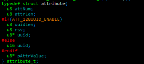
ATT attribute table: const attribute_t gAttributes[] array is defined by users. The data structure is shown as below.
Refer to the source code as below.
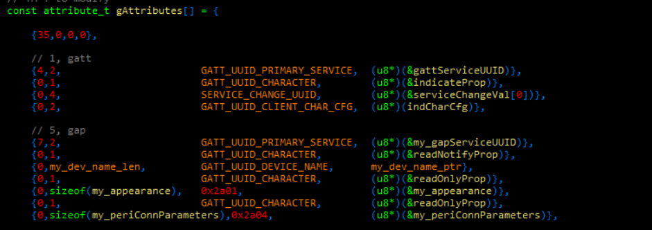
In the first row, 35 is the total number of entries.
The first segment in the first line of each subsequent section is the number of entries in this group (4 and 7 in the above screenshot), the other segments are attrLen (length of the attribute), uuid (unique identifier of the attribute), pAttrValue (pointer to the attribute value) depending on the data structure. Once properly configured, the phone can read, write and send a notify.
Usage for 128bit UUID
If the UUID is the 128bit version, the gAttributes array needs to be redefined. There are three steps.
(1) Enable the macro in App_confg.h, #define ATT_128UUID_ENABLE 1

(2) Link the lib of uuid128
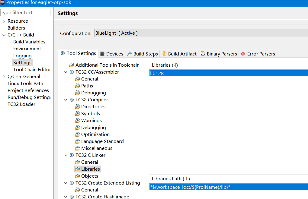
(3) Modify gAttributes array to meet the uuid128 requirement. There is an example in vendor -> blueLight -> blueLight-128-uuid.h. Then clean and recompile.
ATT attribute read and write callbacks
(1) Callback: int attWriteCallback (void *pp)
The type of pp pointer is rf_packet_att_write_t, and from the pp pointer the handle value and data can be obtained. Then the user can perform logical processing based on handle and data. If this function returns 0, the system writes the data to the pAttrValue corresponding to the handle in the att attribute table; if it returns 1, it does not write (meaning that the user has already processed it and the system ignores it).
(2) Callback: int attReadCallback (void *pp, void *pRsp)
Normally this function returns 0 directly and leaves it to the system. The system will read the value from the attribute table pAttrValue and return it.
(3) void spp_notify (u8* buf, u16 len)
The user can send a notify to the phone by calling spp_notify. This function is only an example and requires the user to fill in the correct handle value in pkt_sppNoti.
RF Parameter Setting
Mac address: void blc_ll_initAdvertising_module (u8 *public_adr)
By default, the system reads the mac address from the OTP parameter area. This function does not need to be called. If the user needs to set the mac, this function can be called.
Advertising enable: int bls_ll_setAdvEnable (int en)
The default is 1. To disable, set to 0.
Advertising interval: int bls_ll_setAdvParam (u16 interval)
The default is 200ms in milliseconds.
Advertising data setting: int bls_ll_setAdvData (u8 *data, u8 len)
Set the advertising data. The length is no greater than 31 bytes.
Scan response data setting: int bls_ll_setScanRspData (u8 *data, u8 len)
Set the scan response data. The length is no greater than 31 bytes.
Link parameter: void bls_l2cap_requestConnParamUpdate (u16 min_interval, u16 max_interval, u16 latency, u16 timeout)
When all parameters are 0, this function is disabled.
Paring enable: int bls_smp_enableParing (u8 encrypt_en)
The default is enabled. To disable, set to 0.
Other Drivers
IO control:
-
IO inputs and outputs: To save space, it is recommended to use the register settings directly. For example: reg_gpio_pa_oen = ~GPIO_LED; reg_gpio_pc_out |= GPIO_C5
-
Pull up and down: use analog registers and macros. For example: analog_write(areg_pull_b4_b7, B4_1M | B5_1M | B6_1M)
-
Wake up: directly use analog registers and macros. For example: analog_write(areg_pb_wakeup_en, GPIO_B4 | GPIO_B5 | GPIO_B6)
Keyboard:
Users can implement a simple key detection (IO high and low level determination) by themselves, or refer to kb_scan_key, this function is an example of an application where one IO is connected to 2 keys. Due to the size limitation of the OTP, there is no example of keyboard row scanning.
PWM:
This is an example of PWM setting:

then you can call pwm_start(0) and pwm_stop(0) to enable or disable PWM.
I2C:
Below is an example of the configuration and application. Note that it uses a single-byte address in the driver. If a 2-byte address is required, please modify the source code in the i2c.c.

ADC:
-
For general chn measurements, first call the adc_general_init(chn) function, then call adc_simple_get to obtain the value.
-
For battery measurement, first call the adc_vbat_init() function, then call adc_simple_get to obtain the value.
UART:
Set the macro UART_BAUD_RATE in app_config.h. Then recompile. The following is an example of configuring UART by IO in the user_init.

Call spp_check in user_loop:
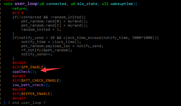
Then implement callback, do the following processing when the UART data is received.

SDK debugging
Tdebug
Check the corresponding variables through the wtcdb tool, and debug by checking the corresponding variables. Need to turn on input enable for sws, and turn off low power mode.
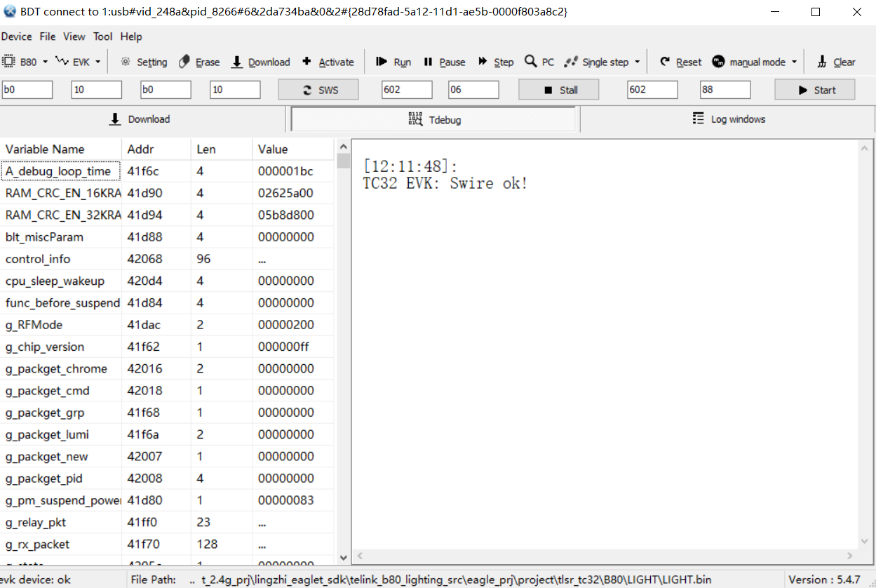
Serial print and debug

Set baudrate and gpio in printf.c and you are ready to print with printf. Due to performance, baudrate is generally not greater than 256000 bps.
Debug using flash
As debugging with OTP is very inconvenient. If a flash version is required to debug, the following steps are required.
(1) Enable in asmConfig.h: #define RUN_ON_FLASH 1

(2) Link to flash lib as below.

(3) Clean and re-compile.