Telink Secure Boot Application Note
Introduction
This application note explains the secure mechanisms such as Secure Boot, Firmware Encryption, and Secure Debug supported in TLSR952x/922x Series SoCs.
Secure Boot protects a device from running any unauthorized code by checking that the firmware that is being booted is signed. In TLSR9, Secure Boot is achieved by running the Boot-ROM code (first stage bootloader) to verify the code inside Flash, the code may include both additional second stage bootloader and application codes which can further perform chained verification. The first stage bootloader is fixed in the chip Boot-ROM at the chip manufacturer. The purpose of the first stage bootloader is to check the security bits to make sure that Encryption, Signature, and Debug Lock are enabled or disabled. These functions are implemented in the first stage bootloader.
Firmware encryption allows the firmware stored on Flash to be encrypted to protect against attacks such as cloning, this is most useful when off-chip Flash is used to store firmware code.
Secure Debug allows all debug interfaces such as SWS and JTAG to be locked so that hackers will not be able to access any on-chip information from these debug interfaces.
The following decision tree can be used to select appropriate secure mechanisms.
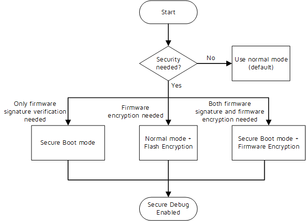
When security is needed, normally either Firmware Signature Verification + Secure Debug or Firmware Encryption + Secure Debug would be able to cover majority use cases.
There may be other possible configuration bits combinations, but we do not recommend using them except for the above cases.
Key Management
The key management is shown in the figure below.
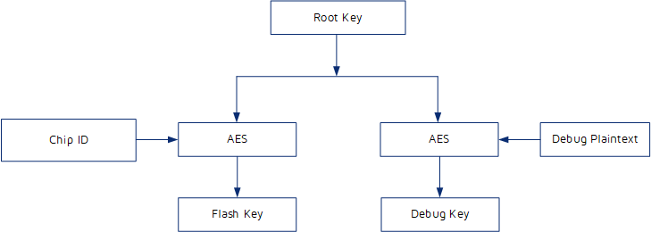
The Flash Key is used for Firmware Encryption, the Debug Key is used to re-enable debug interface, shown as the figure above. The Flash Key is derived from the Root Key (provided by customer) and the Chip ID (unmodifiable) through AES128 (ECB) derivation. The Debug Key is derived from the Root Key (provided by customer) and the Debug Plaintext (provided by customer) through AES128 (ECB) derivation.
Note:
The Root Key and the Debug Plaintext are random numbers. The customer generates and keeps them, and the security is also kept by the customer.
eFuse and Flash Layout
eFuse
The non-volatile eFuse is defined as below.
| Name | Default | Description |
|---|---|---|
| Security_Feature | 32'd0 | [31] Flash Encryption Enable [30] reserved [29] mode selection, 1: secure boot mode (verified signature), 0: normal mode [28:0] Reserved for Telink internal use |
| pub_key_hash | 256'd0 | Hash public key |
| debug_text | 128'd0 | Debug Plaintext |
| chip_id | 128'd0 | Chip ID, unmodifiable Identification of the chip, unique for each chip |
| root_key | 128'd0 | Root Key |
| Interface functions | 32'd0 | [31:16] Reserved [15] if_sws_disable: SWS function disable. 1'b1: disable; 1'b0: enable. [14] if_jtag_disable: JTAG function disable. 1'b1: disable; 1'b0: enable. [13:0] Reserved |
Note:
- The bit of eFuse can only be written from 0 to 1, not from 1 to 0. That is, once a bit is written to 1 as the way Telink specified, it cannot be changed.
- User applications cannot access eFuse directly as the read/write permission is restricted.
Flash Space in Secure Boot Mode
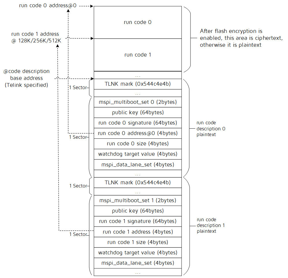
The flash may contain several segments of data including code 0 & 1, and their corresponding code description 0 & 1. When allocating flash, each segment area should not overlap. The code description is only present if secure boot with firmware signature verification is enabled.
The code, which has a fixed starting address of 0, is the firmware code to be executed. It is in plaintext if firmware encryption is not enabled; If the firmware encryption is enabled, the code is stored as ciphertext (encrypted firmware). The code is automatically loaded after power on.
The code description block provides information about the corresponding firmware code.
- The Telink Mark is a fixed string pattern stored in the register of 0x544c4e4b. The first stage bootloader only execute the corresponding code 0 or code 1 with a valid corresponding Telink Mark, and realize switching the code to be executed.
- The mspi_multiboot_set is used to set parameters related to run code address, and the details refer to How to set mspi_multiboot_set and run code address in How to generate run code description.
- The public key is used to verify the code signature.
- The run code signature is the calculated signature over the running code.
- The run code address is the starting address of the running code.
- The run code size is the length of the code field in Bytes.
- The watchdog target value is the watchdog capture value. This value should be set large enough to allow firmware signature verification process to finish before watchdog resets, please use the default value provided by Telink.
- The mspi_data_lane_set is to set the desired MSPI width for the running data. The data lane mode can be selected from 2-lane and 4-lane, please use the default value provided by Telink.
The flash space allocation for code description base address is shown in the following table.
| Flash size (bytes) | Code description base address (Telink specified) |
|---|---|
| 1M | 0xf8000 |
| 2M | 0x1f8000 |
| 4M | 0x3f8000 |
| 16M | 0xff8000 |
Flash Space in Normal Mode

There is no firmware signature verification in normal mode, therefore code description is not required.
The run code can be started at any address among 0, 128K, 256K, 512K bytes. It is in plaintext if firmware encryption is not enabled; If the firmware encryption is enabled, the code is stored as cipher- text (encrypted firmware).
Secure Boot
Secure Boot Introduction
The Elliptic Curve Digital Signature Algorithm (ECDSA) is a secure verification scheme which uses key-pair (Public/Private key) derived from elliptic curve cryptography (ECC). The public key is stored on chip in Flash and the public key hash is stored on chip in eFuse. The corresponding private key is kept at a secret place and is never accessed by the chip or any intermediaries. Only one public key can be generated and stored in the chip during manufacturing.
The Secure Boot process involves the following steps:
During power up, the Boot-ROM (first stage bootloader) loads the firmware in Flash, which can be either second stage bootloader or application code. The firmware’s signature is verified. If the verification is successful, the firmware is executed.
Most of the time, the firmware can be directly the application code for simplicity.
Note that in some case, the user may also would like to have more flexibility in controlling application code and thus prefer to use chained secure boot verification. In this case, the Boot-ROM verifies the above firmware which is a second stage bootloader. After the second stage bootloader is verified and executed and when it loads a particular application image, the application signature is verified. If the verification is successful, the application image is executed. The Second stage bootloader can use a Public/Private key mechanism selected by the customer and can be different from the default approach.
Secure Boot verifies the firmware using a dedicated control block as described in Flash Space in Secure Boot Mode, where both the public key and the signature is stored.
The Secure Boot process follows these steps:
On startup, the Boot-ROM code checks the mode selection bit in the eFuse. If Secure Boot is disabled, a normal boot will be executed. If Secure Boot is enabled, the boot will proceed according to the following steps.
The Boot-ROM code verifies the public key hash, calculates the hash value of the public key (in flash), and compares it with the public key hash (in eFuse). If they are equal, the verification passes; if not, the verification fails. When the verification has passed, the Boot-ROM code verifies the firmware’s signature. The diagram describing the process of ECDSA key pair generating and signature signing is as below.

From the above figure, we can see that the Secure Boot tool generates key pair and signature, the first stage bootloader verifies the signature and returns the result of success or fail.
The related key generating functions are as follows.
(1) Generate private public key pairs. Input: Curve (Secp256r1); output: Private key (big-endian), Public key (big-endian).
ecc_getkey (Curve, Private key, Public key)
(2) Specify the private key to generate the public key. Input: Curve (Secp256r1), Private key (big-endian); output: Public key (big-endian).
ecc_get_pubkey_from_prikey (Curve, Private key, Public key)
Note:
(1) Telink uses the standard ECC algorithm with curve parameters secp256r1 (is equivalent to prime256v1). If the ECC curve (Secp256r1) and the endianness of the key (big-endian) match, the key generated by Secure Boot tool is the same as the key generated by a third-party tool (such as Openssl). (2) If customer needs to integrate this tool to their own environment. the source code of private key generation function can be made available to customer to use for relevant functions (secure boot tool used), therefore customer can generate key pairs and signature in their own code.
How To Enable Secure Boot
How To Generate Run Code Description
Here the application for generating run code description is introduced.
(1) Implementation method
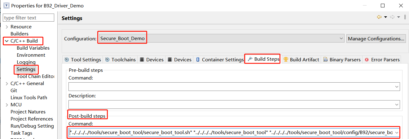
Download the SDK, import the B92 project in the IDE tool. Open settings in the Menu -> Project -> Properties -> C/C++ Build. In the Configuration drop-down list, select Secure_Boot_Demo, the Post build command is configured in the following figure, it is used to execute the script secure_boot_tool.sh and call secure_boot_tool.
Input: secure_boot_tool_cfg.ini, run code
Output: run code description and etc.
(2) Parameter configuration
Open the corresponding secure_boot_tool_cfg.ini file (if it does not link to the project, you can open it under tools\secure_boot_tool\config\B92).
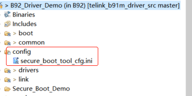
- How to produce Public Key and Private Key pair
Private key has following two methods to generate, refer to the figure below:
a. If you do not fill in the secure_boot_tool_cfg.ini (cfg.ini for short) or fill in the data length does not match, the secure_boot_tool will automatically generate a set of Private_key and write to the corresponding location in the cfg.ini file.
b. Manually write a random number (big-endian, 32 bytes) in cfg.ini as a Private Key. Ensure that there is sufficient entropy in the random number. The tool will specify the private key to generate the public key.

Public key
Once the private key is confirmed, build Secure_Boot_Demo and generate a one-to-one public key to fill in the corresponding run descriptor.
Note:
After the key pair is generated, the private key is kept at a secret place and is never accessed by the chip or any intermediaries.
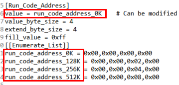
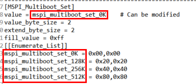
- How to set run code address and mspi_multiboot_set
As shown in secure_boot_tool_cfg.ini of the following figure.
run code address_X, in which, X represents the absolute address of run code in the flash: 0K-0x00, 128K-0x20000, 256K-0x40000, 512K-0x80000.
Configure value=[Enumerate_list], mspi_multiboot_set_X is related with run code address_X, so the X of them should be consistent.
- mspi_data_lane and watchdog target value
They are using default value, users can ignore the setting for them.
(3) Output result
The demo source is:
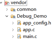
Build the configuration Secure_Boot_Demo,

The Public Key and Private Key Pair, the corresponding run code, run code description and public_key_hash.bin will be generated together. The corresponding information will be output in the console as below.

eFuse and Flash Download
eFuse burning prerequisite
As shown in the figure below, before burning eFuse, the test point EF1 of this development board should be connected to 2.5V DC power supply. For different development boards, the EF1 may be soldered with a header, and the location of EF1 may be different.
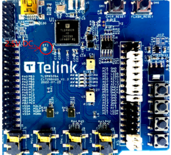
Note
No power supply required after burning.
After hardware preparation is completed, open BDT tool, click Tool -> Secure Boot Tool to open the corresponding window.
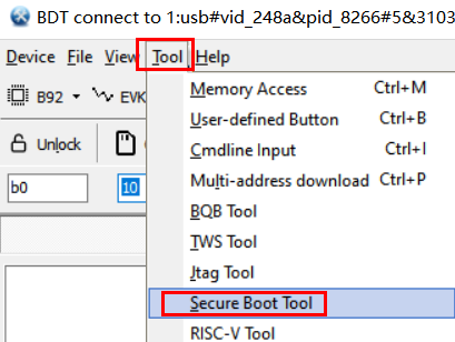
The eFuse information must be burned is as follows.
| eFuse bit | Note |
|---|---|
| mode selection | Secure boot mode enable |
| pub_key_hash | The hash calculated over the public key used by customer for firmware signature verification. It cannot be changed. |
Follow the below steps to do the burning.
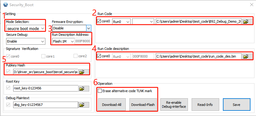
(1) For "Mode Selection", select secure boot mode (otherwise it is normal mode, no description required).
(2) Select run code 0 or run code 1 for firmware, select run code address which is consistent with Flash Space in Secure Boot Mode, and import the firmware path.
(3) Select flash size, the corresponding code description base address will be confirmed accordingly.
(4) Select run code description path and import.
(5) Public key hash will load automatically (if not, import the public_key_hash.bin manually).
(6) Operation:
a. We should click Download-All for the first burning.
b. If not for the first burning, we can click Download-Flash.
c. We can choose whether erase the TLNK mark in another run code description. For example, for run1, checking this box (Erase alternative code TLNK mark) will erase the run0 TLNK mark.
Note:
- Restrictions after Secure Boot is enabled.
- Any updated firmware will need to be signed with a key matching the public key hash already stored in eFuse.
- Generate the signing key on a system with a quality source of entropy.
- Keep the signing key private at all times. A leak of this key will compromise the Secure Boot system.
- If run code is larger than 512KB, it is not suitable to use run0 and run1 to do OTA update. Instead, a second stage bootloader scheme is recommended, where the 2nd stage bootloader starts at Flash address 0x0000 and it performs both OTA function and also subsequent signature verification for application firmware. (The corresponding application document will be released afterwards.)
Firmware Encryption
Firmware Encryption Introduction
The firmware is encrypted by hardware when it is downloaded to flash. The firmware stored in the flash is ciphertext. When the chip is running, it will decrypt the firmware in real time.
Note:
The BDT is not responsible for the conversion of plaintext to ciphertext. The hardware on chip performs the encryption when the firmware is downloaded to flash while encryption is turned on.
The OTA process for firmware encryption can be divided to two segments:
(1) Delivery process: The server delivers OTA image to device in any encryption method chosen either by customer or Telink. Upon receiving the image, it is first decrypted by Telink MCU based on the encryption algorithm.
(2) Burning process: The Telink MCU writes plain image into Flash where the image is encrypted by the on-chip hardware on the fly.
How To Enable Firmware Encryption
The eFuse information must be burned is as follows.
| eFuse bit | Note |
|---|---|
| Firmware Encryption | Enable |
| Root Key (128 bits) | Root Key, a customer provided key for Flash Key derivation. No need of repeat burning if it was burned for secure debug. |
| chip_id | unmodifiable |
Follow the below steps to do the burning.
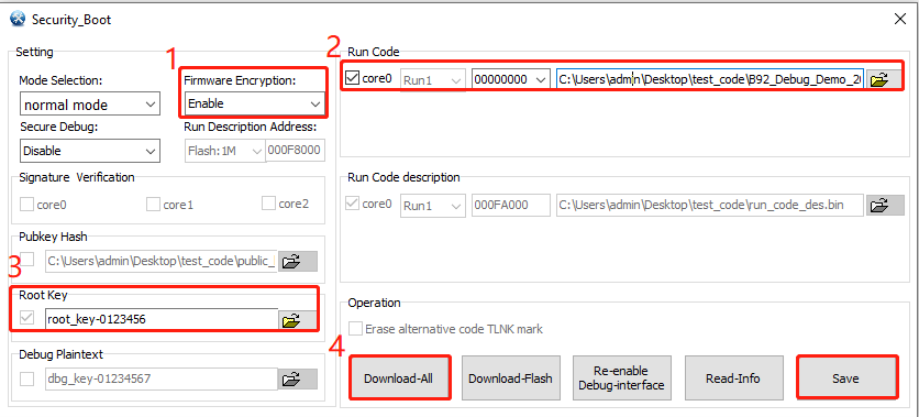
(1) For Firmware Encryption, select Enable (otherwise this function is disabled).
(2) Select run code for firmware, select run code address and import firmware path.
(3) Select Root Key, manually enter specified text (supports strings or hexadecimal).
(4) Click Download-All.
Note:
- The Root Key supports text box input and text file (strings or hexadecimal) import. The tool automatically checks the length.
- Click the Save button and the Root Key will be saved under the config\sboot\key path. If you don't want it to leak into future processes, save them to a secret place.
Secure Debug
Secure Debug Introduction
When Secure Debug is enabled, the debug interface is disabled that is no means to access any registers or memories within the chip through debug interface.
If the user wants to re-enable debug interface function, he/she needs to send Debug Key sequence according to the single wire protocol.
How to Enable Secure Debug
The eFuse information must be burned is as follows.
| eFuse bit | Note |
|---|---|
| Root Key (128 bits) | Customer provides for Debug Key derivation. No need of repeat burning if it was burned for firmware encryption. |
| Debug Plaintext (128 bits) | Customer provides for Debug Key derivation. |
Follow the below steps to do the burning.
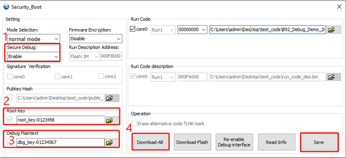
(1) For Secure Debug, select Enable (otherwise this function is disabled), the SWS interface is not disabled.
(2) Select Root Key, manually enter specified text.
(3) Select Debug Plaintext, manually enter specified text.
(4) Click Download-All.
Note:
- The Root Key and plaintext support text box input and text file (strings or hexadecimal) import. The tool automatically checks the length.
- Click the Download-All button to generate the Debug Key, which will be saved under the config\sboot\key path regardless of whether the download is successful or not.
- Click the Save button, the Root Key and the Debug Plaintext will be saved to the config\sboot\key path. If you don't want them to leak into later processes, save them to a secret place.
How to Re-enable Debug Interface
Follow the following steps to re-enable Debug Interface.
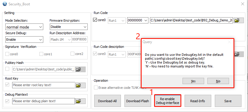
(1) Click the Re-enable Debug-interface button.
(2) The pop-up dialog box.
- Yes: use the DebugKey.txt file in the default folder as the Debug Key.
- No: manually import the DebugKey.txt file as the Debug Key.
Note:
- Before clicking re-enable Debug, we should ensure that the single wire is always in the idle state, that is, no operation is performed on the single line after powering up. The tool has already done the power down and power up after clicking the button.
- After re-powering or reset, the Debug Key will be lost and you need to re-enable the debug interface again.
Recommended Usage Options
On TLSR9 series chip, the different secure mechanisms: Secure Boot, Firmware Encryption and Secure Debug can be enabled separately and thus allowing many different combinations. However, in practice, we recommend the following combinations to be used:
- Option 1: Secure Boot + Secure Debug
- Option 2: Normal Mode + Firmware Encryption + Secure Debug
- Option 3: Secure Boot + Firmware Encryption + Secure Debug
Note that whenever the firmware encryption is used, the secure debug must be enabled to avoid information related to the flash encryption key to be exposed.
Option 1 Secure Boot + Secure Debug
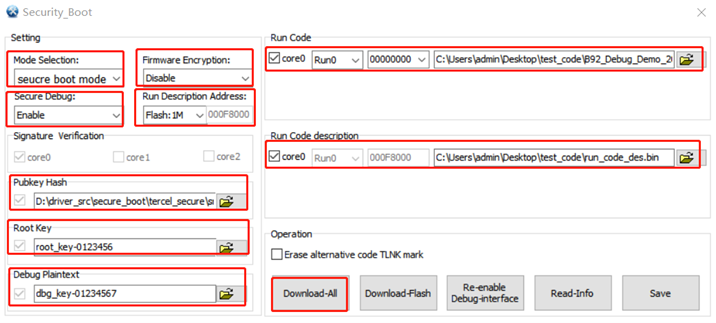
Step 1: See section How to Enable Secure Boot
Step 2: See section How to Enable Secure Debug
Step 3: Download-All
Note:
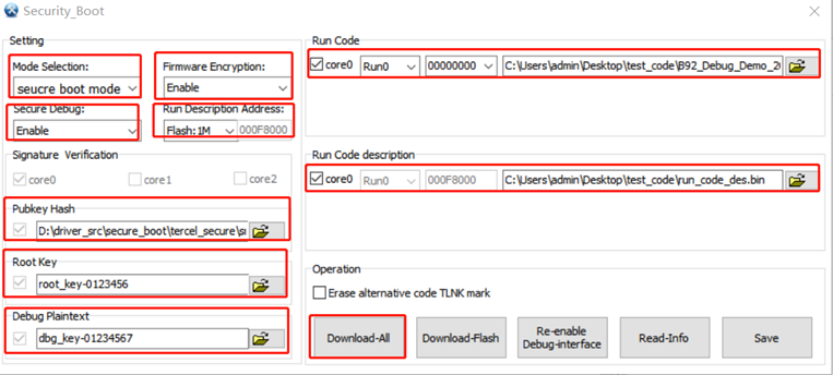
In step 1 and step 2, mode selection must be consistent (Secure Boot mode) and do not download, click Download-All in step 3, as shown in the figure below.
Option 2 Normal Mode + Firmware Encryption + Secure Debug
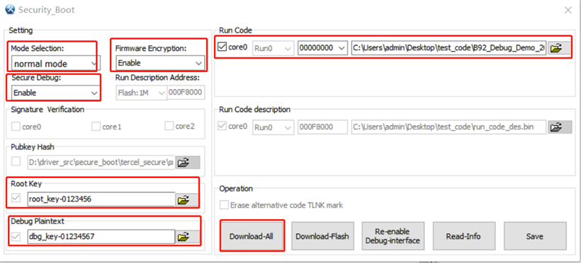
Step 1: For mode selection, select normal mode (default)
Step 2: See section How to Enable Firmware Encryption
Step 3: See section How to Enable Secure Debug
Step 4: Download-All
Note:
In step 2 and step 3, mode selection must be consistent (normal mode) and do not download, click Download-All in step 4, as shown in the figure below.
Option 3 Secure Boot + Firmware Encryption + Secure Debug
Step 1: See section How to Enable Secure Boot
Step 2: See section How to Enable Firmware Encryption
Step 3: See section How to Enable Secure Debug
Step 4: Download-All
Note:
In step 1, step 2 and step 3, mode selection must be consistent (Secure Boot mode) and do not download, click Download-All in step 4, as shown in the figure below..
Other Operation
Read-Info: Read eFuse configuration information, excluding the Root Key and the Debug Plaintext.
Save: Manually save the interface configuration information in config\sboot\.ini. The Root Key and the Debug Plaintext will be saved to the config\sboot\key path.
