Telink tl_ble_sdk Developer Handbook
SDK Overview
The tl_ble_sdk provides reference code for BLE multiple connection applications, allowing users to develop their own applications based on this foundation. Multiple connection refers to the coexistence of multiple (greater than or equal to 1) Central or Peripheral roles, such as functioning simultaneously as 4 Centrals and 3 Peripherals (referred to as C4P3). Currently the stack supports up to 4 Centrals, and up to 4 Peripherals, and does not support the free conversion of roles.
Starting from tl_ble_sdk V4.0.4.4 version, SDK and Handbook are released at the same time, and the content of this version of Handbook corresponds to tl_ble_sdk V4.0.4.4.
Starting from tl_ble_sdk V4.0.4.2 version, the release SDK has been moved from the official Wiki to Gitee and GitHub, code download or Clone do not need to login account. In order to receive timely updates of the SDK, it is recommended to watch the repository after logging in.


Applicable ICs
The current tl_ble_sdk applies to B91 (TLSR921x and TLSR951x), B92 (TLSR922x and TLSR952x), TL321X, TL721X, TL322x series MCUs.
Software Organization Structure
After importing the tl_ble_sdk in Telink IoT Studio, the displayed file structure is shown in the figure below (take B91 as an example). There are 8 top layer folders: algorithm, application, boot, common, drivers, proj_lib, stack and vendor.

algorithm: This folder contains some general algorithms, such as aes_ccm. The C files corresponding to most algorithms are supplied in the form of library files, leaving only the corresponding header files.
application: This folder contains general application program, e.g. usb, keyboard, and etc.
boot: This folder contains software bootloader for MCU and the link script .link file. The cstartup_
common: This folder contains generic across platforms definitions, such as assert, BIT(x), etc.
drivers: This folder contains MCU peripheral drivers, e.g. Clock, Flash, I2C, USB, GPIO, UART. Corresponding to the release version of tl_platform_sdk, users can refer to doc/tl_platform_sdk_Release_Note.md.
proj_lib: This folder contains library files necessary for SDK running. BLE stack, RF driver, PM driver, etc. are supplied in the form of library files. Different chips use different library files.
stack: This folder contains header files for BLE stack. Source files supplied in the form of library files are not open to users.
vendor: This folder contains example code or user's application layer code.
Vendor

The tl_ble_sdk provides 3 basic demonstrations:
-
acl_peripheral_demo: Advertising, itself as a reference code for Peripheral to be connected by other Central, default configuration is C0P4, enable SMP, deep retention sleep.
-
acl_central_demo: Scanning, itself as a reference code for Central to establish connection with other Peripheral, default configuration is C4P0, enable SMP, sleep is not configured.
-
acl_connection_demo: Both advertising and scan, itself can be used as the reference code for Peripheral or Central to connect with other devices at the same time, default configuration is C4P4, enable SMP, Suspend sleep.
The feature_test/ contains the reference code for each feature, please refer to Feature Demonstrations.
The common/ contains generic modules for the application layer, such as
-
boards/: This folder contains the generic configurations of all the development boards supported by this SDK.
-
battery_check.c/.h: It provides the handling scheme for low power protection, please refer to Low Battery Detect section for more details.
-
ble_flash.h: It declares Flash related interfaces, and definitions, such as Flash Map.
-
blt_soft_timer.c/.h: It provides the implementation scheme of software timer.
-
default_config.h: It provides the default definitions for the application layer configuration macros, users can override the default definitions by defining them in app_config.h.
-
device_manage.c/.h: Management of connection device information (e.g. connection handle, attribute handle, BLE device address, address type, etc.).
-
simple_sdp.c/.h: This file provides the simple SDP (Service Discovery Protocol) implementation scheme for the Central role.
-
tlkapi_debug.c/.h: This file provides the Debug logging interface implementation.
The following acl_connection_demo as an example to explain the demonstration file structure, the file composition is shown in the following figure:

main.c
The main.c file contains the main function and the interrupt handler function.
The main function is the entry point of program and contains the configuration required for the system to work properly. It is recommended that users do not make any modifications to it. Additionally, the tl_ble_sdk supports a minimum main frequency (CCLK) of 32MHz.
The interrupt handler function is the entry function when the system triggers an interrupt.
app_config.h
The user configuration file "app_config.h" servers to configure parameters of the whole system (e.g. BLE parameters, GPIO configuration, low power enable/disable, encryption enable/disable, etc.).
Each parameter in app_config.h will be explained in detail when each module is introduced in the following sections.
Application Files
app.c/.h: User main file for BLE system initialization, data processing and low power management.
app_att.c/.h: Provides GATT service table and profile file. GATT service table has provided the standard GATT service, standard GAP service, standard HID service and some private service. Users can refer to these to add their own service and profile.
app_ui.c/.h: Primarily provides keystroke handling interface and logic.
app_buffer.c/.h: This file is used to define the buffers used by each layer of the stack, such as: LinkLayer TX & RX buffer, L2CAP layer MTU TX & RX buffer, HCI TX & RX buffer, etc.
app_freertos.c/.h: When the FREERTOS_ENABLE macro is enabled, the interface within this file will be called to run the FreeRTOS operating system.
BLE Stack Entry
The BLE interrupt handler entry function is blc_sdk_irq_handler().
The BLE logic and data handling entry function is blc_sdk_main_loop(), which is responsible for handling data processing and event reporting related to the BLE stack.
Version Number
In older versions of tl_ble_sdk, the version number was logged using sdk_version.txt. This method has been deprecated.
Users can use the following function to get the current SDK version information, the feature of this API has been adjusted in version V4.0.4.4.
unsigned char blc_get_sdk_version(unsigned char *pbuf,unsigned char number);
The parameter pbuf is a pointer to an array storing version information, the parameter number is the length of that array, and the return value is the actual length needed for the version information string. If the return value is 0, it means that the input array length is not enough and needs to be expanded.
When used, the user needs to first define a large array to obtain the version information, passes the array and its size as parameters to the function, and then prints the return value and string, the reference code is as follows:
 u8 sdk_ver[180] = {0};
 u8 sdk_ver_len = blc_get_sdk_version(sdk_ver, 180);
 tlkapi_printf(1, "Version Info[%d]:%s\n", sdk_ver_len, sdk_ver);
After running, it prints content like "Version Info[95]:V4.0.4.4_P0001 C0.0 Develop 105b2c862 Thu Jun 19 21:09:30 2025 +0800 Dirty 2025-06-19 23:29:58", which means that the size of the string array needed for the actual version information is 95 bytes, the code can be modified to:
    u8 sdk_ver[95] = {0};
    u8 sdk_ver_len = blc_get_sdk_version(sdk_ver, 95);
    tlkapi_printf(1, "Version Info[%d]:%s\n", sdk_ver_len, sdk_ver);
MCU Basic Modules
MCU Address Space
Flash
Please refer to the corresponding Datasheet for the Flash size supported by various MCUs.
The program will be burned in the Flash starting from 0x0.
The basic unit of Flash read and write is byte, user can call flash_write_page()/flash_read_page() to achieve read and write operation.
Info
- Due to the limitation of Flash design, the basic unit of Flash read and write driver layer is page(256 bytes), so the interface name here is xx_page.
The basic unit of Flash erase is sector (4K bytes), and whole sector can be erased by calling flash_erase_sector().
Note
- Before writing, the Flash should be erased first, a page in Flash is 256 bytes, flash_write_page function supports write operation across pages.
The tl_ble_sdk reads the MID of Flash by calling blc_readFlashSize_autoConfigCustomFlashSector() during initialization to get the Flash size for the auto-configuration of the underlying Flash Map, refer to the following diagram and the vendor/common/ble_ flash.h definition (note replace [Flash Size] in the following):

-
CFG_ADR_MAC_[Flash Size]_FLASH: the location where the BLE MAC address is saved, refer to blc_initMacAddress() for usage.
-
For B91, if this section in Flash is all 0xFF, a random MAC address starting with Telink Company ID will be generated.
-
For B92, TL321x, TL721x, TL322x, if this section in Flash is all 0xFF, the built-in MAC address will be read from the corresponding location in eFuse/OTP.
-
-
CFG_ADR_CALIBRATION_[Flash Size]_FLASH: The starting location of RF calibration parameter saving, related code refer to user_calib_freq_offset().
-
FLASH_ADR_SMP_PAIRING_[Flash Size]_FLASH: The starting location of SMP pairing information storage, occupies 16KB, its storage structure refers to smp_param_save_t in stack/ble/host/smp/smp_storage.h, and the details refer to the following SMP section below.
-
FLASH_SDP_ATT_ADDRESS_[Flash Size]_FLASH: As Client, after doing simple SDP, it will store the ATT information of the remote Server in Flash.
Note
- The areas defined above are occupying the whole sector, users are not allowed to use these sectors for other purposes.
In addition, if user configures Secure Boot on B92, TL321x or TL721x chips, a fixed Flash area will be used for the Secure Boot configuration, see the above figure. Users can customize the storage space of these sectors if they don't need Secure Boot.
SRAM
The SRAM size supported by various MCUs, please refer to the corresponding Datasheet. I-SRAM can store instructions and data, D-SRAM can only store data.
For different models of B92 and TL721x series MCUs, there will be differences in SRAM resources, which require users to configure the definitions of IRAM and DRAM sizes in the boot/[Chip Name]/cstartup_[Chip Name].S file according to the actual I-SRAM and D-SRAM. Take the B92 as an example:
##define SRAM_SIZE      SRAM_128K

##if (SRAM_SIZE == SRAM_256K)
    .equ __IRAM_2_EN,   1
    .equ __DRAM_1_EN,   0
    .equ __DRAM_2_EN,   0
    .equ __DRAM_DIS,    1
##elif (SRAM_SIZE == SRAM_384K)
    .equ __IRAM_2_EN,   1
    .equ __DRAM_1_EN,   1
    .equ __DRAM_2_EN,   0
    .equ __DRAM_DIS,    0
##elif (SRAM_SIZE == SRAM_512K)
    .equ __IRAM_2_EN,   1
    .equ __DRAM_1_EN,   1
    .equ __DRAM_2_EN,   1
    .equ __DRAM_DIS,    0
##else
    .equ __IRAM_2_EN,   0
    .equ __DRAM_1_EN,   0
    .equ __DRAM_2_EN,   0
    .equ __DRAM_DIS,    1
##endif
Note
- The I-SRAM and D-SRAM configurations only have a few fixed configurations listed in cstartup_[Chip Name].S and are not freely combinable by the user.
MCU Address Space Allocation
For the Memory Map of various MCUs, please refer to the corresponding Datasheet. Taking the TLSR9218A of B91 as an example, in the Datasheet's 4.1.1 SRAM chapter, which introduces its Memory Map. The SDK focuses on the following address spaces:

-
Address range of CPU accessing I-SRAM (ILM_CPU): 0x00000000~0x00020000
-
Address range of CPU accessing D-SRAM (DLM_CPU): 0x00080000~0x000A0000
-
Address range of Flash space (FLASH): 0x20000000~0x21000000
-
Address range of registers (USB, AUDIO, ZB, etc.): 0x80100000~0x82000000
-
Address range of bus access to I-SRAM (ILM): 0xC0000000~0xC0020000
-
Address range of bus access D-SRAM (DLM): 0xC0200000~0xC0220000
Info
- From the above figure, it can be seen that I-SRAM or D-SRAM can be accessed through CPU or through bus (e.g. DMA, Swire), and the different access addresses are used to distinguish the way of accessing. As seen in the above figure, CPU can also access through bus.
Flash and SRAM Space Allocation
The tl_ble_sdk will configure the mode of deepsleep retention by calling blc_app_setDeepsleepRetentionSramSize() based on the size of the actual SRAM to be used for retention (e.g., DEEPSLEEP_MODE_RET_SRAM_ LOW32K). The following figure shows the corresponding SRAM and Firmware space allocation for the case where both I-SRAM and D-SRAM are used at the same time in the deepsleep retention 32K mode, using the B91 as an example.

The SRAM space allocation related files in the above figure are cstartup_B91.S and boot_general.link.
The compiled and generated Firmware is downloaded to the Flash and its contents include vectors, retention_reset, retention_data, ram_code, text, rodata and data initial value.
After power-on startup, part of the contents of the Flash are carried to the I-SRAM and D-SRAM.
The I-SRAM contains retention_reset, aes_data, retention_data, ram_code, and unused I-SRAM area. The retention_reset/retention_data/ram_code in the I-SRAM is a copy of retention_reset/retention_data/ram_code in Flash.
The D-SRAM contains data, sdata, bss, sbss, heap, unused D-SRAM area and stack. The initial value of data in D-SRAM is the data initial value in Flash.
Segments Introduction
data, sdata and data initial value
The "data" or "sdata" segment stores a global variable with a non-zero initial value. The sdata is the abbreviation of small data. Its initial value is stored in the "data initial value" segment of the Flash Firmware and it will be copied to the corresponding SRAM address of the variable when the bootloader is running.
sbss and bss
The "sbss" and "bss" segments store global variables that the programme has not been initialized or has been initialized to 0, i.e. global variables with an initial value of 0. The sbss is the abbreviation for small bss. When running the bootloader, the whole SRAM of this segment will be set to 0 directly.
text
The "text" segment is the segment that functions in a program are compiled to by default. Instructions that access the "text" segment must pass through the I-Cache. Instructions that need to be executed must first be loaded into the I-Cache before they can be executed.
rodata
The "rodata" segment stores readable, non-rewritable variables defined in the programme and located in Flash, such as variables defined with the keyword "const".
ram_code
The "ram_code" segment is a memory-resident code in the Firmware, which is copied from Flash to the ram_code area of the I-SRAM by the MCU after power-on, and its content contains the functions defined in the SDK with the keyword _attribute_ram_code_ xxx, such as the rf_irq_handler function:
_attribute_ram_code_ void rf_irq_handler(void);
Functions are memory-resident for three reasons:
(1). Some functions must be memory-resident because they involve timing multiplexing with the four Flash MSPI pins, and if they are put into Flash, there will be timing conflicts, resulting in a crash, such as all functions related to Flash operation;
(2). The function that is executed in ram does not need to be re-read from Flash when it is called each time, which can save time, so for some functions with execution time requirements can be put into the memory-resident to improve the execution efficiency. In the SDK, some functions related to BLE timing that are frequently executed are resident in memory, which greatly reduces the execution time and saves power consumption.
Note
- The tl_ble_sdk supports interrupt nesting feature, please refer to Interrupt Nesting chapter for details, if user added LEV3 priority interrupt entry function, it must be put into the "ram_code" segment.
If users need to make a function memory-resident, they can follow the example of rf_irq_handler above, add the keyword _attribute_ram_code_ to the function, and then they can see the function in the ram_code segment in the objdump file after compiling.
retention_data
The "retention_data" segment is the data that needs to be resident in the memory of the Firmware, which is copied from Flash to the retention_data area of the I-SRAM by the MCU after power-on or normal deepsleep wake-up. After deepsleep retention hibernation, the data in the specified retention area of the I-SRAM is kept not power down (refer to definition pm_sleep_mode_e).
By default, global variables in the programme are assigned to the "data", "sdata", "sbss", or "bss" segments. They are not restricted for storage in the retention area of the I-RAM, and will be lost when entering the deepsleep retention.
If users want some specific variables to be maintained during deepsleep retention mode, it is necessary to assign them to the "retention_data" segment by adding the keyword _attribute_data_retention_ when defining the variable. The following are a few examples:
_attribute_data_retention_  int     AA;
_attribute_data_retention_  unsigned int BB = 0x05;
_attribute_data_retention_  int CC[4];
_attribute_data_retention_  unsigned int DD[4] = {0,1,2,3};
vectors and retention_reset
The "vectors" segment and the "retention_reset" segment are programs corresponding to the assembly file cstartup_
aes_data
The "aes_data" segment stores the cached data of the hardware AES module. The aes_data segment is on the I-SRAM and is fixed to 32 bytes in length, which cannot be changed by the user. When running the bootloader, this segment will be all set to zero.
_retention_size_
The "retention_reset + aes_data + retention_data + ram_code" of the I-SRAM are 4 segments sequentially arranged in the front of the I-SRAM, and their total size is "_retention_size_". After the MCU is powered up or woken up from a normal deepsleep, as long as the program does not enter a normal deepsleep (only suspend/deepsleep retention) during execution, the content of "_retention_size_" will remain on the I-SRAM, and MCU doesn't need to read it from the Flash again.
The method to evaluate "_retention_size_" is to add the "Size" and "VMA" of the "ram_code" segment according to the "Sections" at the beginning of the objdump file, which is the actual size of the "_retention_size_". For example, the size of "_retention_size_" in the following figure is 0x5b02 + 0xf00, about 26.5KB.

If users select the configuration using deepsleep retention 32K mode, but the defined "_retention_size_" exceeds the defined 32K, for example, the size of "_retention_size_" in the following figure is 0x5b02 + 0x3700, which is about 36.5KB, it exceeds 32K, so the compilation check will report an error.

Users can modify it in the following ways:
(1). Reduce the content of the defined "_attribute_data_retention_" segment or "_attribute_ram_code_" segment attribute.
(2). Switch to a mode with a larger size than deepsleep retention according to the chip support conditions.
Cache
This cache is high-speed cache, and it is divided into I-Cache and D-Cache, each with a fixed size of 8KB, and the access address is not visible to the user.
Cache is enabled by default and is configured in the cstartup_
  /* Enable I/D-Cache */
    csrr   t0,  mcache_ctl
    ori    t0,  t0,  1  #/I-Cache
    ori    t0,  t0,  2  #/D-Cache
    csrw   mcache_ctl,  t0
    fence.i
Memory-resident code can be read and executed directly from SRAM, but only part of the code in Firmware can be resident in SRAM, and most of the rest is still in Flash. According to the principle of program locality, a part of Flash code can be loaded into Cache, if the code that needs to be executed now is in Cache, it will be read and executed directly from Cache; if it is not in Cache, it will be read from Flash and loaded into Cache and then executed.
Firmware's "text" and "rodata" segments are not put into SRAM, this part of the code satisfies the principle of programme locality, and needs to be always loaded into the Cache to be executed.
Since the Cache is relatively large, users are not allowed to use the pointer form to read Flash, because the data read in the form of pointer is cached in the Cache, if the data in the Cache is not covered by other contents, even if the Flash data at the location has been rewritten and there is a new request to access the data, in this case, the MCU will directly use the cached content in the Cache as the result.
heap
The "heap" area is allocated to the heap, the heap is growing upwards, generally it is set to the unused space behind the bss, if you call sprintf/malloc/free such memory management functions, these functions will call the _sbrk function for the allocation of heap memory, and _sbrk will determine from where to start allocating heap space by using the _end symbol. It is defined in the link file as follows.
PROVIDE (_BSS_VMA_END = .);
    ...
    . = ALIGN(8);
    /* end is the starting address of the heap, the heap grows upward */
    _end = .;
    PROVIDE (end = .);
stack
For 128KB D-SRAM, the "stack" starts from the highest address 0x000A0000, and its direction extends from the bottom to the top, i.e., the stack pointer SP is self-decreasing when data enters the stack and self-adding when data exits the stack.
If stack is used too large, then there may be a stack overflow situation, which overlaps with the .bss segment, resulting in a program running error. See Appendix 2 for the principle and method of checking the stack.
Taking the B91 as an example, the boot_general.link file contains the stack top location _STACK_TOP:
PROVIDE (_STACK_TOP = 0x00a0000);/*Need to prevent stack overflow*/
The stack pointer sp register is initialized in the cstartup_B91.S file:
/* Initialize stack pointer */
la     t0, _STACK_TOP
mv     sp, t0
If users want all of the 128KB D-SRAM space to be reserved for users to use or the D-SRAM is not used, the all data and instructions occupied by the SDK can be put into the I-SRAM.
Clock Module
The clock module refers to the Clock chapter in the Datasheet of each MCU.
Call API blc_app_system_init() to configure pll_clk/cclk/hclk/pclk/clk_mspi during initialization, take TL321x for example:

Note
- The CCLK of multi-connect SDK is configured with at least 24 MHz system clock, other clocks can not satisfy the operation of multi-connect SDK.
- In the TL_BLE_SDK, the default CCLK for the TL321x is up to 48 MHz. For higher CCLK, please refer to the LPC_demo in the tl_platform_sdk and make the necessary modifications.
- In the TL_BLE_SDK, the default CCLK for the TL322x is up to 96 MHz. For higher CCLK, please refer to the LPC_demo in the tl_platform_sdk and make the necessary modifications.
The frequency of System Timer of B91 is fixed at 16MHz, and the frequency of System Timer of B92, TL321x, TL721x, TL322x is fixed at 24MHz. Since System Timer is the base of BLE timing, all BLE time related parameters and variables in SDK when they involve the expression of time are expressed as "SYSTEM_TIMER_TICK_xxx", and the following values are used to express s, ms, and us (take TL321x as an example):
enum
{
    SYSTEM_TIMER_TICK_1US = 24,
    SYSTEM_TIMER_TICK_1MS = 24000,
    SYSTEM_TIMER_TICK_1S  = 24000000,

    SYSTEM_TIMER_TICK_625US  = 15000, //625*24
    SYSTEM_TIMER_TICK_1250US = 30000, //1250*24
};
The following APIs in the SDK are related to some operations of System Timer, and these APIs internal already use the above similar "xxx_TIMER_TICK_xxx" way to represent the time. When the user operates these APIs, input us or ms according to the formal parameter prompt.
void delay_us(unsigned int microsec);
void delay_ms(unsigned int millisec);
_Bool clock_time_exceed(unsigned int ref, unsigned int us)
Usage of System Timer
After the initialization of sys_init in main function, System Timer starts to work, and users can read the value of System Timer counter (abbreviated as System Timer tick).
System Timer tick every clock cycle increase one, its length is 32bit, the minimum value 0x00000000, the maximum value 0xffffffff. System Timer just start, tick value is 0. B91 every 1/16 us increase 1, to the maximum value of 0xffffffff the time required is: (1/16) us * (2^32) which is approximated to 268 seconds, and every 268 seconds System Timer ticks one turn. B92 increases 1 every 1/24 us, and the time needed to reach the maximum value 0xffffffff is: (1/24) us * (2^32) which is approximated to 178 seconds, and every 178 seconds System Timer ticks one turn.
The system tick does not stop when the MCU is running the programme.
The reading of System Timer tick can be obtained by clock_time() function:
u32 current_tick = clock_time();
Interrupt Nesting
Function Introduction
The tl_ble_sdk supports interrupt nesting functionality, which involves three concepts: interrupt priority, interrupt threshold, and interrupt preemption.
(1) Interrupt priority refers to the level assigned to each interrupt, which needs to be configured during interrupt initialization.
(2) The interrupt threshold is the level that determines which interrupts are responded to; only interrupts with a priority higher than the interrupt threshold will be triggered.
(3) Interrupt preemption occurs when two interrupts have priorities above the interrupt threshold. If a lower-priority interrupt is currently being handled, a higher-priority interrupt can be triggered, preempting the lower-priority interrupt. Once the higher-priority interrupt is completed, the system will resume handling the lower-priority interrupt.
Note
- The interrupt nesting feature is enabled by default, and the interrupt threshold is set to 0 by default.
The range for setting interrupt priority is from 1 to 3. Currently, the highest priority level that can be set is 3, with a higher number indicating a higher priority. The priority enumeration is as follows:
typedef enum{
    IRQ_PRI_LEV0,//Never interrupt
    IRQ_PRI_LEV1,
    IRQ_PRI_LEV2,
    IRQ_PRI_LEV3,
}irq_priority_e;
As shown in the diagram below, the BLE SDK has defined three types of interrupt priorities, and users must adhere to this classification. Interrupt priority LEV1 has the lowest level and is assigned to user-defined APP normal interrupts. Interrupt priority LEV2 is of intermediate level and is reserved for BLE interrupts; user-defined interrupts cannot use LEV2. Interrupt priority LEV3 has the highest level and is generally not recommended for use, except in specific situations that require real-time response; it is also assigned to user-defined APP advanced interrupts.

In the initialization function blc_ll_initBasicMCU, the BLE SDK has set the interrupt priority of the BLE interrupts ("rf_irq" and "stimer_irq") to IRQ_PRI_LEV2, and the interrupt threshold is set to 0 (interrupts with priorities LEV1 to LEV3 can be triggered).
User-defined APP normal interrupts need to have their interrupt priority set to IRQ_PRI_LEV1, and there are no execution time constraints. BLE interrupts and APP advanced interrupts can preempt APP normal interrupts.
If users require APP advanced interrupts, they need to set the interrupt priority to IRQ_PRI_LEV3. When using APP advanced interrupts, please note the following:
-
The interrupt handler function must be placed in the ram_code section.
-
Accessing Flash memory is not allowed within the interrupt handler function.
-
The execution time of the interrupt handler function must be less than 50 us.
When performing erase, read, and write operations in Flash memory, the interrupt threshold will be set to 1. After completing the Flash operation functions, the interrupt threshold will be reset to 0. This allows BLE interrupts and user APP advanced interrupts to be interleaved during Flash read and write operations. If the BLE interrupt and user APP advanced interrupt functions are stored in Flash, timing conflicts may arise between the Flash prefetch operations and the read/write operations, potentially leading to a system freeze. Similarly, if there are read/write operations within the BLE interrupt and user APP advanced interrupt functions, multiple Flash operations may also lead to timing conflicts and cause a freeze. Therefore, it is essential to place the BLE interrupt and user APP advanced interrupt functions in the ram_code section, and access to Flash memory must be prohibited within these functions. Since user APP advanced interrupts can preempt BLE interrupts and APP normal interrupts, users must also ensure that the execution time of advanced interrupt functions is less than 50 us to avoid impacting BLE interrupts.
Using Interrupt Nesting
App Normal Interrupt
For example, if a user wants to set a PWM APP normal interrupt, they should define the interrupt priority as IRQ_PRI_LEV1 during the configuration. The method is as follows:
plic_set_priority(IRQ16_PWM, IRQ_PRI_LEV1);
There are no restrictions on the type of interrupt response function.
void pwm_irq_handler(void)
{
        ……
}
APP Advanced Interrupt
For example, if a user wants to set a Timer0 APP advanced interrupt, they should define the interrupt priority as IRQ_PRI_LEV3 during the configuration. The method is as follows:
plic_set_priority(IRQ4_TIMER0, IRQ_PRI_LEV3);
The interrupt response function must be defined in the ram_code section. The method is as follows:
_attribute_ram_code_ void timer0_irq_handler(void)
{
        ……
}
Interrupt Usage Restrictions
BLE interrupts require timely responses. Therefore, whether it's an APP interrupt with a priority of IRQ_PRI_LEV3 or a situation where the user disables global interrupts, the maximum duration is limited to 50 us. Users need to pay special attention to this point.
BLE Module
This handbook refers to Bluetooth Core Specification version 6.0.
BLE SDK Software Architecture
Standard BLE SDK Software Architecture
According to Bluetooth Core Specification, a standard BLE SDK architecture is shown in the figure below.

In the architecture shown above, the BLE protocol stack is divided into two parts, Host and Controller.
-
The Controller works as the lower layer protocol of BLE, including Physical Layer (PHY) and Link Layer (LL). Host Controller Interface (HCI) is the only communication interface between Controller and Host, and all data interaction between Controller and Host is completed through this interface.
-
The Host works as BLE upper layer protocol, the protocol has Logic Link Control and Adaption Protocol (L2CAP), Attribute Protocol (ATT), Security Manager Protocol (SMP), Profile includes Generic Access Profile (GAP) and Generic Attribute Profile (GATT).
-
The application layer (APP) contains the user's own related application code and various service corresponding profiles, and the user controls access to the Host through the GAP. The Host completes data interaction with the Controller through the HCI, as shown in the following figure.

(1) The BLE Host operates and sets the Controller through HCI cmd.
(2) The Controller reports various HCI events to the Host through HCI.
(3) The Host transmits the data that needs to be sent to the other party device to the Controller through HCI, and the Controller drops the data directly to the Physical Layer for sending.
(4) The Controller in the Physical Layer received RF data, first determine whether the data belongs to the Link Layer or Host: If it is Link Layer data, process the data directly; If it is the data of the Host, the data will be transmitted to the Host through HCI.
Telink BLE SDK Software Architecture
Telink BLE Multiple Connection Controller
The tl_ble_sdk supports standard BLE controller, including HCI, PHY (Physical Layer) and LL (Link Layer).
The tl_ble_sdk contains the five standard states of the Link Layer (standby, advertising, scanning, initiating, connection), The connection state supports up to 4 Central roles and 4 Peripheral roles at the same time.
The controller architecture is as follows:

Telink BLE Multiple Connection Whole Stack (Controller+Host)
The tl_ble_sdk provides BLE multiple connection Whole Stack (Controller + Host) reference design, Only for Central SDP (service discovery) can not be fully supported, which will be introduced in detail in the following chapters.
Telink BLE stack architecture will do some simplification to the standard structure above, so that the system resource overhead (including Sram, Running time, Power consumption, etc.) of the whole SDK is minimized, and its architecture is shown in the figure below. The demos provided in the SDK are based on this architecture.

The data interaction shown by the solid arrow in the figure can be operated and controlled by the user through various interfaces, and the user API will be provided. The hollow arrow is the data interaction completed within the protocol stack, and the user cannot participate.
HCI is the data communication interface between Controller and Host (docking with L2CAP layer), but it is not the only interface. APP application layer can also directly interact with Link Layer for data. The Power Management (PM) low power management unit is embedded into the Link layer, and the application layer can call the relevant interfaces of PM to set the power management.
Considering the efficiency, the data interaction between the application layer and Host is not controlled through GAP to access, the protocol stack provides relevant interfaces in ATT, SMP and L2CAP, which can interact directly with the application layer. However, all Events of Host need to interact with the application layer through the GAP layer.
The Host layer is based on Attribute Protocol and implements Generic Attribute Profile (GATT). The application layer is based on GATT and defines the various profiles and services that the user needs. This BLE SDK provides several basic profiles, including HIDS, BAS, OTA, etc.
Based on this architecture, the following is a basic introduction to each part of the BLE multiple connection protocol stack, and give the user API of each layer.
The Physical Layer is completely controlled by the Link Layer and does not require any participation from the application layer, so this part is not introduced.
Although the Host and Controller part of the data interaction or rely on HCI to complete, basically completed by the host and controller protocol stack, the application layer is almost not involved, only needs to register the HCI data callback processing function in the L2CAP layer, so the HCI part is not introduced.
Controller
Connection Number Configuration
supportedMaxCentralNum & supportedMaxPeripheralNum
The tl_ble_sdk refers to the maximum number of Connection Central roles as supportedMaxCentralNum and the maximum number of Connection Peripheral roles as supportedMaxPeripheralNum. They are determined by the library, as shown in the following table:
Table: Correspondence between the maximum number of supported Centrals and Peripherals and the library
IC library supportedMaxCentral-Num supportedMaxPeripheralNum
B91 liblt_9518 4 4
B92 liblt_9528 4 4
TL721X liblt_TL721X 4 4
TL321X liblt_TL321X 4 4
The SDK can query the number of Central and Peripheral supported by the current stack through the following API.
int blc_ll_getSupportedMaxConnNumber(void);
appMaxCentralNum & appMaxPeripheralNum
With the premise that supportedMaxCentralNum and supportedMaxPeripheralNum have been determined, users can set the maximum number of Central and Peripheral they want in their applications through the following API, which are called appMaxCentralNum and appMaxPeripheralNum respectively.
ble_sts_t blc_ll_setMaxConnectionNumber(int max_master_num, int max_slave_num);
This API is only allowed to be called during initialization, that is, the number of relevant connections needs to be determined before the Link Layer runs, and it is not allowed to be modified later.
The user's appMaxCentralNum and appMaxPeripheralNum must be less than or equal to supportedMaxCentralNum and supportedMaxPeripheralNum.
The reference example design uses this API during initialization:
blc_ll_setMaxConnectionNumber(ACL_CENTRAL_MAX_NUM, ACL_PERIPHR_MAX_NUM);
Users need to define their own appMaxCentralNum and appMaxPeripheralNum in app_config.h, which are ACL_CENTRAL_MAX_NUM and ACL_PERIPHR_MAX_NUM in the SDK.
##define ACL_CENTRAL_MAX_NUM       4
##define ACL_PERIPHR_MAX_NUM       4
appMaxCentralNum and appMaxPeripheralNum can save various resources of MCU, for example, for the C4P 4 library, if the user only needs to use C3P2, after setting ACL_CENTRAL_MAX_NUM and ACL_PERIPHR_MAX_NUM to 3 and 2 respectively:
(1) Save SRAM resources
Link Layer TX Central FIFO and TX Peripheral FIFO, L2CAP Central MTU buffer and L2CAP Peripheral MTU buffer are allocated according to appMaxCentralNum and appMaxPeripheralNum, so it can save some Sram resources. For details, please refer to the TX FIFO related introduction at the back of the document.
(2) Save time resources and power consumption
For C4P4, Stack must wait until currentCentralNum is 4 to stop the Scan action, and must wait until currentPeripheralNum is 4 to stop the Advertising action. For C3P2, Stack waits until the currentCentralNum is 3 to stop the Scan action, and the currentPeripheralNum is 2 to stop the Advertising action, so that there is less unnecessary Scan and Advertising, which can save the PHY layer bandwidth and reduce MCU power consumption.
currentMaxCentralNum & currentMaxPeripheralNum
After the user defines appMaxCentralNum and appMaxPeripheralNum, the maximum number of Central and Peripheral created at Link Layer runtime is determined. However, the number of Central and Peripheral at a given moment is still uncertain, for example, if appMaxCentralNum is 4, the number of Central at any moment may be 0,1,2,3,4.
The SDK provides the following 3 APIs for users to query the current number of Central and Peripheral on the Link Layer in real time.
int blc_ll_getCurrentConnectionNumber(void);    //Central + Peripheral connection number
int blc_ll_getCurrentCentralRoleNumber(void);   //Central role number
int blc_ll_getCurrentPeripheralRoleNumber(void);//Peripheral  role number
Link Layer State Machine
Users can first refer to the introduction of the Link Layer state machine in the Telink B91 BLE Single Connection SDK, the five basic states of Link Layer are supported. If the Connection state is divided into Connection Peripheral role and Connection Central role, Link Layer must be and can only be one of the following six states at any time: Standby, Advertising, Scanning, Initiating, Connection Peripheral role, Connection Central role.
For tl_ble_sdk, because to support multiple Central and Peripheral at the same time, Link Layer can't be in only one state at a certain moment, it must be a combination of several states.
The Link Layer state machine of the tl_ble_sdk is complex. Just a general introduction can meet the user's basic understanding of the lower layer and the use of the corresponding API.
Link Layer State Machine Initialization
The tl_ble_sdk designs each basic state according to modularity, and the modules that need to be used need to be initialized in advance.
MCU initialization is necessary. The API is as follows:
void blc_ll_initBasicMCU (void);
The Add API for the Standby module is as follows, this is necessary and all BLE applications need to be initialized.
void blc_ll_initStandby_module (u8 *public_adr);
The actual parameter public_adr is the pointer to BLE public mac address.
The initialization APIs of the corresponding modules for several other states (Advertising, Scanning, ACL Central, ACL Peripheral) are as follows:
void   blc_ll_initLegacyAdvertising_module(void);
void   blc_ll_initLegacyScanning_module(void);
void   blc_ll_initAclConnection_module(void);
void   blc_ll_initAclCentralRole_module (void);
void   blc_ll_initAclPeripheralRole_module(void);
Link Layer State Combination
The Initiating state is relatively simple. when the Scan state needs to initiate a connection to a advertising device, the Link Layer enters the Initiating state, and within a certain period of time (this time is called create connection timeout) either the connection is established successfully and there is an additional Connection Central role, or the connection is established unsuccessfully and the Link Layer returns to the Scanning state. In order to simplify the introduction of Link Layer state machine and make it easier for users to understand, the brief temporary state of Initiating is ignored in the following introductions.
The Link Layer state machine in the tl_ble_sdk can be described from two perspectives: one is the transition between Advertising and Peripheral; the second is the transition between Scanning and Central; these two perspectives do not affect each other.
Take C1P1 as an example analysis, assuming that the user's appMaxCentralNum and appMaxPeripheralNum are both 1. The state machine for C1P1 Advertising and Peripheral switching is as follows:

In the figure, adv_enable and adv_disable refer to the state set by the user's last call to blc_ll_setAdvEnable(adv _enable) when the condition occurs.
The state machine for C1P1 Scanning and Central switching is as follows:

In the figure, scan_enable and scan_disable refer to the state set by the user's last call to blc_ll_setScanEnable (scan_enable, filter_duplicate) when the condition occurs.
The Advertising and Peripheral, Scanning and Central, each of them have 3 states, and since the logic between the two is completely independent and does not affect each other, then the final Link Layer combination state has a total of 3*3=9, as shown in the following table:
Table: C1P1 Link Layer Combination Status
2A 2B 2C
1A Standby Scanning Central
1B Advertising Advertising + Scanning Advertising + Central
1C Peripheral Peripheral + Scanning Peripheral + Central
Take a more complex C4P4 analysis, assuming that the user's appMaxCentralNum and appMaxPeripheralNum are 4 and 4 respectively, the state machine for C4P4 Advertising and Peripheral switching is as follows:

The state machine for C4P4 Scanning and Central switching is as follows:

Advertising and Peripheral have 9 possible states, and Scanning and Central have 9 possible states. Since the logic between the two is completely independent and does not affect each other, then the final Link Layer combination state has a total of 9*9=81 kinds, as shown in the following table:
Table: C4P4 Link Layer Combination Status
| / | 2A | 2B | 2C | 2D | 2E | 2F | 2G | 2H | 2I |
|---|---|---|---|---|---|---|---|---|---|
| 1A | Standby | Scanning | Scanning Central*1 |
Scanning Central*2 |
Scanning Central*3 |
Central*4 | Central*1 | Central*2 | Central*3 |
| 1B | Adv | Adv Scanning |
Adv Scanning Central*1 |
Adv Scanning Central*2 |
Adv Scanning Central*3 |
Adv Central*4 |
Adv Central*1 |
Adv Central*2 |
Adv Central*3 |
| 1C | Adv Periphr*1 |
Adv Periphr*1 Scanning |
Adv Periphr*1 Scanning Central*1 |
Adv Periphr*1 Scanning Central*2 |
Adv Periphr*1 Scanning Central*3 |
Adv Periphr*1 Central*4 |
Adv Periphr*1 Central*1 |
Adv Periphr*1 Central*2 |
Adv Periphr*1 Central*3 |
| 1D | Adv Periphr*2 |
Adv Periphr*2 Scanning |
Adv Periphr*2 Scanning Central*1 |
Adv Periphr*2 Scanning Central*2 |
Adv Periphr*2 Scanning Central*3 |
Adv Periphr*2 Central*4 |
Adv Periphr*2 Central*1 |
Adv Periphr*2 Central*2 |
Adv Periphr*2 Central*3 |
| 1E | Adv Periphr*3 |
Adv Periphr*3 Scanning |
Adv Periphr*3 Scanning Central*1 |
Adv Periphr*3 Scanning Central*2 |
Adv Periphr*3 Scanning Central*3 |
Adv Periphr*3 Central*4 |
Adv Periphr*3 Central*1 |
Adv Periphr*3 Central*2 |
Adv Periphr*3 Central*3 |
| 1F | Periphr*4 | Periphr*4 Scanning |
Periphr*4 Scanning Central*1 |
Periphr*4 Scanning Central*2 |
Periphr*4 Scanning Central*3 |
Periphr*4 Central*4 |
Periphr*4 Central*1 |
Periphr*4 Central*2 |
Periphr*4 Central*3 |
| 1G | Periphr*1 | Periphr*1 Scanning |
Periphr*1 Scanning Central*1 |
Periphr*1 Scanning Central*2 |
Periphr*1 Scanning Central*3 |
Periphr*1 Central*4 |
Periphr*1 Central*1 |
Periphr*1 Central*2 |
Periphr*1 Central*3 |
| 1H | Periphr*2 | Periphr*2 Scanning |
Periphr*2 Scanning Central*1 |
Periphr*2 Scanning Central*2 |
Periphr*2 Scanning Central*3 |
Periphr*2 Central*4 |
Periphr*2 Central*1 |
Periphr*2 Central*2 |
Periphr*2 Central*3 |
| 1I | Periphr*3 | Periphr*3 Scanning |
Periphr*3 Scanning Central*1 |
Periphr*3 Scanning Central*2 |
Periphr*3 Scanning Central*3 |
Periphr*3 Central*4 |
Periphr*3 Central*1 |
Periphr*3 Central*2 |
Periphr*3 Central*3 |
If the user's appMaxCentralNum/appMaxPeriphrNum is not C1P1 or C4P4, please analyze according to the above analysis method.
The concepts of supportedMaxCentralNum/supportedMaxPeripheralNum and appMaxCentralNum/appMaxPeripheralNum were introduced earlier, corresponding to the number of Central and Peripheral in the above state machine combination table, two concepts currentCentralNum and currentPeripheralNum were defined to indicate the actual number of Central and Peripheral in the Link Layer at the current moment, for example, in the '1D2E' combination state in the above table, currentCentralNum is 3 and currentPeripheralNum is 2.
Link Layer Timing
Link Layer timing is complex, here is only the introduction of some of the most basic knowledge, enough for users to understand, and rational use of related APIs.
The five basic single states of Link Layer are Standby, Advertising, Scanning, Initiating, and Connection. Ignoring the short Initiating, which is only used when the Central create connection, we only briefly introduce the timing of the remaining four states.
In this section, we use the C4P4 state as an example to illustrate, assuming that appMaxCentralNum and appMaxPeripheralNum are 4 and 4, respectively.
Each sub-state (Advertising, Central0 \~ Central3, Peripheral0 \~ Peripheral3, Scanning, UI task) will be indicated by the following figure:

Standby State Timing
Corresponds to the 1A2A state of C4P4 in the table 3.3.
When the Link Layer is in Idle state, the Link Layer and Physical Layer do not have any tasks to process, and the blc_sdk_main_loop function does not work at all and does not produce any interrupts. It can be considered that UI entry (UI task) occupies the whole main_loop time.

Scanning only, no Adverting, no Connection Timing
Corresponds to the 1A2B state of C4P4 in the table 3.3.
At this time, only the Scanning state needs to be processed and Scan is the most efficient. The Link Layer switches channel 37/38/39 according to the Scan interval, and the timing diagram is as follows:

According to the size of the Scan window to determine the true Scan time, if the Scan window is equal to the Scan interval, all the time in the Scan; if the Scan window is less than the Scan interval, select the time equal to the Scan window from the front in the Scan interval to Scan.
The Scan window shown in the figure is about 60% of the Scan interval, , in the first 60% of the time, the Link Layer is in the Scanning state, and the PHY layer is receiving packets, at the same time, the user can use this time to execute their UI task in main_loop. The last 40% of the time is not in the Scanning state, the PHY layer stops working, the user can use this time to execute their UI task in main_loop. For the design of the low power management to be described later, this time also allows the MCU to enter into suspend to reduce the power consumption of the whole machine.
Advertising only, no Scanning, no Connection Timing
Corresponds to the 1B2A state of C4P4 in the table 3.3.
The Advertising Event is allocated to the timeline according to the Adv interval and the timing diagram is as follows:

For all the details of Adv Event, just refer to the details of Adv Event in the Telink B91 BLE Single Connection SDK, both of them are the same.
Users can use non-Adv time to execute their own UI task in main_loop.
Advertising, Scanning, no Connection Timing
Corresponds to the 1B2B state of C4P4 in the table 3.3.
First, according to the Adv interval, the Advertising Event is first allocated to the timeline, and then the Scanning is allocated, the timing diagram is as follows:

Since the application requires higher timing accuracy for advertising than scan, Adv Event has higher priority at this time, first allocate the timing of Adv Event, then use the remaining time between Adv Event for Scan, while the users can use this remaining time to execute their own UI task in main_loop. When the Scan window set by the user is equal to the Scan interval, the Scan duration in the figure will fill the remaining time; when the Scan window set by the user is less than the Scan interval, the Link Layer will automatically calculate and get a Scan duration that satisfies the following condition: Scan duration/(Adv interval + rand_dly) should be equal to Scan window/Scan interval as much as possible.
Connection, Advertising, Scanning Timing
The number of Connection connections has not yet reached the set maximum, and the advertising and scanning states still exist at this time.
The following figure corresponds to the 1C2C state C4P4 in the table 3.3.

The allocation of connection tasks (whether Central or Peripheral) is done first and will be allocated according to the timing of the respective connections. If multiple tasks occupy the same time slot and conflict occurs, they will be allocated according to the priority and preempted with high priority. Abandoned tasks are automatically increased in priority to ensure that they are not always discarded.
Then the adv task is allocated, the principle is:
(1) The time interval from the last adv event should be greater than the set minimum adv interval time.
(2) The time between and the next task is greater than a certain value (3.75ms), because adv takes a certain amount of time to complete.
(3) The allocated time period is not occupied by other connection tasks.
Finally the allocation of scan tasks, the principle is: as long as there is more than enough time between the two tasks, this time is allocated to the scan tasks, and the percentage of the scan is also confirmed according to the scan window/Scan interval.
Connection, no Advertising, no Scanning Timing
The number of Connection connections has reached the set maximum, and there are no advertising and scanning states at this time.
The following figure corresponds to the 1G2H state of C4P4 in the table 3.3.

The following figure corresponds to the 1I2F state of C4P4 in the table 3.3.

At this time, only connected tasks are assigned according to the respective connected timings. If a conflict occurs, it will be allocated according to the priority, the high priority tasks will preempt, abandoned tasks are automatically given increased priority, increasing the chances of grabbing them in the next conflict.
ACL TX FIFO & ACL RX FIFO
ACL TX FIFO Definition and Setting
Application layer and BLE Host all the data eventually need to complete the RF data sent through the Controller's Link Layer, in the Link Layer according to the number of connections set by the user, the corresponding TX FIFO is defined.
The ACL TX FIFO is defined as follows:
u8  app_acl_cen_tx_fifo[ACL_CENTRAL_TX_FIFO_SIZE * ACL_CENTRAL_TX_FIFO_NUM * ACL_CENTRAL_MAX_NUM] = {0};
u8  app_acl_per_tx_fifo[ACL_PERIPHR_TX_FIFO_SIZE * ACL_PERIPHR_TX_FIFO_NUM * ACL_PERIPHR_MAX_NUM] = {0};
The TX FIFO of ACL Central and ACL Peripheral are defined separately. Take ACL Peripheral as an example, ACL Central principle is the same, and so on.
The size of the array app_acl_per_tx_fifo is related to three macros:
(1) ACL_PERIPHR_MAX_NUM is the maximum number of connections, i.e. appMaxPeripheralNum. Users can modify this value in app_config.h as needed.
(2) ACL_PERIPHR_TX_FIFO_SIZE is the size of each sub_buffer, which is related to the possible maximum value of data sent by the ACL Peripheral. Use the following macro to define the implementation in the SDK.
##define ACL_PERIPHR_TX_FIFO_SIZE CAL_LL_ACL_TX_FIFO_SIZE(ACL_PERIPHR_MAX_TX_OCTETS)
Among them, CAL_LL_ACL_TX_FIFO_SIZE is a formula, which is related to the implementation of MCU. Different MCU calculation methods may be different. Please refer to the notes in app_buffer.h for details.
ACL_PERIPHR_MAX_TX_OCTETS is the user-defined PERIPHRMaxTxOctets. if the client uses DLE (Data Length Extension), this value needs to be modified accordingly; the default value is 27, which corresponds to the minimum value when DLE is not used, which is used to save Sram. For details, please refer to the comments in app_buffer.h and the detailed description in Bluetooth Core Specification.
(3) ACL_PERIPHR_TX_FIFO_NUM, the number of sub_buffer, please refer to the comments in app_buffer.h for the selection of this value. This value has a certain relationship with the amount of data sent in the client application, if the amount of data sent is large and the real-time requirement is high, you can consider a larger number.
The user defines the TX FIFO according to the actual situation, and the Central TX FIFO and the Peripheral TX FIFO are defined separately, so that one is for each connection's data are cached in their own TX FIFO, the TX data between each connection will not interfere with each other; the second is also according to the actual situation, flexible definition TX FIFO size, corresponding to reduce the consumption of ram. For example:
- The Peripheral needs the DLE function, while the Central does not need DLE, so that the FIFOs can be defined separately to save ram space. For the explanation of DLE, please refer to "MTU and DLE".
- For example, if the customer is actually using 3 Central and 2 Peripheral, the customer can define only 3 Central tx fifo and 2 Peripheral tx fifo, thus reducing the use of ram and saving ram space:
##define ACL_CENTRAL_MAX_NUM                        3
##define ACL_PERIPHR_MAX_NUM                        2
Below we describe the settings of the TX FIFO in various states with a diagram, so that you can have a more intuitive understanding. Here we Take B91 as an example, other chips are the same principle, and so on.
(1) C4P4, ACL Central, ACL Peripheral do not use DLE
Assume that the relevant definitions are as follows:
##define ACL_CENTRAL_MAX_NUM                    4
##define ACL_PERIPHR_MAX_NUM                    4
##define ACL_CENTRAL_MAX_TX_OCTETS          27
##define ACL_PERIPHR_MAX_TX_OCTETS          27

##define ACL_CENTRAL_TX_FIFO_SIZE        CAL_LL_ACL_TX_FIFO_SIZE(ACL_CENTRAL_MAX_TX_OCTETS)
##define ACL_CENTRAL_TX_FIFO_NUM                8
##define ACL_PERIPHR_TX_FIFO_SIZE        CAL_LL_ACL_TX_FIFO_SIZE(ACL_PERIPHR_MAX_TX_OCTETS)
##define ACL_PERIPHR_TX_FIFO_NUM                8
Then the TX FIFO is defined as the following value:
u8  app_acl_cen_tx_fifo[48 * 8 * 4] = {0};
u8  app_acl_per_tx_fifo[48 * 8 * 4] = {0};
The figure is as follows:
Each connection corresponds to a tx fifo, and the number of each connection fifo is 8 (0 \~ 7), and the size of 0 \~ 7 is the same (48B):

(2) C4P4, ACL Central uses DLE and CentralMaxTxOctets is maximum 251, ACL Peripheral does not use DLE.
Assume that the relevant definitions are as follows:
##define ACL_CENTRAL_MAX_NUM                    4
##define ACL_PERIPHR_MAX_NUM                    4
##define ACL_CENTRAL_MAX_TX_OCTETS          251
##define ACL_PERIPHR_MAX_TX_OCTETS          27

##define ACL_CENTRAL_TX_FIFO_SIZE        CAL_LL_ACL_TX_FIFO_SIZE(ACL_CENTRAL_MAX_TX_OCTETS)
##define ACL_CENTRAL_TX_FIFO_NUM                8
##define ACL_PERIPHR_TX_FIFO_SIZE        CAL_LL_ACL_TX_FIFO_SIZE(ACL_PERIPHR_MAX_TX_OCTETS)
##define ACL_PERIPHR_TX_FIFO_NUM                8
Then the TX FIFO is defined as the following value:
u8  app_acl_cen_tx_fifo[272 * 8 * 4] = {0};
u8  app_acl_per_tx_fifo[48 * 8 * 4] = {0};
As can be seen from the figure, the number of FIFOs for each connection of Central and Peripheral is the same, which is 8 (0 ~ 7). However, each FIFO size of the Central is 272B, while the FIFO size of the Peripheral is 48B.

(3) C3P2, ACL Central, ACL Peripheral do not use DLE

ACL RX FIFO Definition and Setting
The ACL RX FIFO is defined as follows:
u8 app_acl_rx_fifo[ACL_RX_FIFO_SIZE * ACL_RX_FIFO_NUM] = {0};
The ACL Central and ACL Peripheral share the ACL RX FIFO. Take ACL Peripheral as an example, ACL Central principle is the same, and so on.
The size of the array app_acl_rx_fifo is related to two macros:
(1) ACL_RX_FIFO_SIZE is buffer size, which is related to the possible maximum value of data received by the ACL Peripheral. Use the following macro definitions in the SDK to implement.
##define ACL_RX_FIFO_SIZE CAL_LL_ACL_RX_FIFO_SIZE(ACL_CONN_MAX_RX_OCTETS)
Among them, CAL_LL_ACL_RX_FIFO_SIZE is a formula, which is related to the MCU implementation, different MCU calculation methods may be different, you can refer to the notes in app_buffer.h for details.
ACL_CONN_MAX_RX_OCTETS is the user-defined PeripheralMaxRxOctets. If the client uses DLE (Data Length Extension), this value needs to be modified accordingly; the default value is 27, which corresponds to the minimum value when DLE is not used, which is used to save Sram. For details, please refer to the comments in app_buffer.h and the detailed description in Bluetooth Core Specification.
(2) ACL_RX_FIFO_NUM, buffer number, please refer to the comments in app_buffer.h for the selection of this value. This value is related to the amount of data received in the client applications, if the amount of data received is large and the real-time requirement is high, you can consider a larger number.
Assume that the C4P4 ACL RX FIFO is defined as follows:
##define ACL_CENTRAL_MAX_NUM                    4
##define ACL_PERIPHR_MAX_NUM                    4

##define ACL_CONN_MAX_RX_OCTETS             27
##define ACL_RX_FIFO_SIZE               CAL_LL_ACL_RX_FIFO_SIZE(ACL_CONN_MAX_RX_OCTETS)
##define ACL_RX_FIFO_NUM                        16
The corresponding ACL RX FIFO allocation is shown below:

RX Overflow Analysis
Refer to the introduction in Telink B91 BLE Single Connection Handbook, the principle is the same.
MTU and DLE Concepts and Usage
MTU and DLE Concepts Description
Bluetooth Core Specification adds data length extension (DLE) from core_4.2.
The Link Layer in the tl_ble_sdk supports data length extension and rf_len length supports the maximum length of 251 bytes in the Bluetooth Core Specification. For details, please refer to Bluetooth Core Specification V5.4, Vol 6, Part B, 2.4.2.21 LL_LENGTH_REQ and LL_LENGTH_RSP.
Before the specific explanation, we need to figure out what the concepts of MTU and DLE are. First look at a picture:

The following figure shows the specific contents of MTU and DLE:

-
MTU stands for Maximum Transmission Unit and is used in computer networking to define the maximum size of a Protocol Data Unit (PDU) that can be sent by a specific protocol.
-
The Attribute MTU (ATT_MTU as defined by the specification) is the largest size of an ATT payload that can be sent between a client and a server. The Bluetooth Core Specification specifies that the minimum value of MTU is 23 bytes.
The DLE is data length extension. The BLE spec specifies that the minimum value of DLE is 27 bytes.
To carry more data in a packet requires negotiation between Central and Peripheral, interacting the DLE size through LL_LENGTH_REQ and LL_LENGTH_RSP.
The Bluetooth Core Specification specifies that the minimum length of DLE is 27 bytes and the maximum is 251 bytes. 251 bytes is because the rf length field is a byte, and the maximum length that can be represented is 255, If it is an encrypted link, it also requires 4 bytes MIC field: 251 + 4 = 255.
MTU and DLE Automatic Interaction Method
If User needs to use the data length extension function, set it as follows. The SDK also provides the corresponding MTU&DLE usage demo, refer to feature_dle in the feature_test project.
Define macro in vendor/feature_test/feature_config.h:
##define FEATURE_TEST_MODE TEST_LL_DLE
(1) MTU size exchange
First, you need to interact with MTU, just modify CENTRAL_ATT_RX_MTU and PERIPHR_ATT_RX_MTU, which represent the RX MTU size of ACL Central and ACL Peripheral respectively. The default is the minimum value of 23, just change it to the desired value. CAL_MTU_BUFF_SIZE is a fixed calculation formula and can not be modified.
The process of MTU size exchange ensures that the minimum MTU size of both parties takes effect, preventing the peer device from being unable to process long packets at the BLE L2cap layer and greater than or equal to 23.
##define CENTRAL_ATT_RX_MTU             23
##define PERIPHR_ATT_RX_MTU             23


##define    CENTRAL_L2CAP_BUFF_SIZE         CAL_L2CAP_BUFF_SIZE(CENTRAL_ATT_RX_MTU)
##define    PERIPHR_L2CAP_BUFF_SIZE         CAL_L2CAP_BUFF_SIZE(PERIPHR_ATT_RX_MTU)
Then the following API is called inside the initialization to set the RX MTU size of ACL Central and ACL Peripheral respectively.
Note
- These two APIs need to be placed in blc_gap_init() to take effect.
blc_att_setCentralRxMTUSize(CENTRAL_ATT_RX_MTU);
blc_att_setPeripheralRxMTUSize(PERIPHR_ATT_RX_MTU);
For the implementation of MTU size exchange, please refer to the detailed description in the "ATT & GATT" section of this document --- Exchange MTU Request, Exchange MTU Response, and also refer to the writing method of feature_dle in the feature_test project.
(2) Set connMaxTxOctets and connMaxRxOctets
Secondly, you need to set the size of the DLE of the Central and Peripheral, refer to the introduction of ACL TX FIFO and ACL RX FIFO, you only need to modify the following macros, and change 27 to the desired value.
##define ACL_CONN_MAX_RX_OCTETS         27
##define ACL_CENTRAL_MAX_TX_OCTETS      27
##define ACL_PERIPHR_MAX_TX_OCTETS          27
Then the following API is called in the initialization to set the rx DLE size and tx DLE size of ACL Central and ACL Peripheral respectively.
ble_sts_t blc_ll_setAclConnMaxOctetsNumber(u8 maxRxOct, u8 maxTxOct_Central, u8 maxTxOct_Peripheral)
(3) Operation of sending and receiving long packets
Please refer to some instructions in the "ATT & GATT" section of this document, including Handle Value Notification and Handle Value Indication, Write request and Write Command, etc.
On the basis that all the above 3 steps are completed correctly, you can start sending and receiving long packets.
To send a long packet, call the APIs corresponding to Handle Value Notification and Handle Value Indication of the ATT layer, as shown below, and bring the address and length of the data to be sent into the following formal parameters "*p" and "len".
ble_sts_t  blc_gatt_pushHandleValueNotify (u16 connHandle, u16 attHandle, u8 *p, int len);
ble_sts_t  blc_gatt_pushHandleValueIndicate (u16 connHandle, u16 attHandle, u8 *p, int len);
To receive long packets, just needs to process the callback function "w" corresponding to Write request and Write Command, and in the callback function, reference the data pointed to by the formal parameter pointer.
MTU and DLE Manual Interaction Method
If the user does not want the stack to automatically interact with MTU/DLE due to some special circumstances, the SDK also provides the corresponding API, and the user decides when to interact with MTU/DLE according to the specific situation. Most of the settings for manual interaction are the same as for automatic interaction, with the differences handled as described below.
For MTU, call API blc_att_setCentralRxMTUSize(23) and blc_att_setPeripheralRxMTUSize(23) when initialization, set the initial MTU to the minimum value of 23, and no automatic interaction is performed after stack comparison. When the user needs to interact with the MTU, call these two APIs (blc_att_setCentralRxMTUSize and blc_att_setPeripheralRxMTUSize) to set the MTU to the actual value, and then just call the API blc_att_requestMtuSizeExchange() to trigger the MTU interaction.
For DLE, you can use API blc_ll_setAutoExchangeDataLengthEnable(0) to disable automatic interaction during initialization, and then call API blc_ll_sendDateLengthExtendReq() to trigger DLE interaction when you need to interact. Refer to the Controller API for specific descriptions of these two APIs.
Coded PHY/2M PHY
Coded PHY and 2M PHY are new features added in Core_v5.0, which largely extend the application scenarios of BLE, Coded PHY includes S2 (500 kbps) and S8 (125 kbps) to adapt to longer distance applications, and 2M PHY (2 Mbps) greatly improves the BLE bandwidth. 2M PHY/Coded PHY can be used in the advertising channel or the data channel in the connected state.
Code PHY/2M PHY API Introduction
(1) API blc_ll_init2MPhyCodedPhy_feature()
void blc_ll_init2MPhyCodedPhy_feature(void);
Used to enable Coded PHY/2M PHY.
(2) API blc_ll_setPhy()
ble_sts_t blc_ll_setPhy( u16 connHandle, le_phy_prefer_mask_t all_phys, le_phy_prefer_type_t tx_phys, le_phy_prefer_type_t rx_phys, le_ci_prefer_t phy_options);
Bluetooth Core Specification standard interface, please refer to Bluetooth Core Specification V5.4, Vol 4, Part E, 7.8.49 LE Set PHY command. Used to trigger the local device to actively apply for PHY exchange. If the determination result of PHY exchange is that the new PHY can be used, the Central device will trigger a PHY update and the new PHY will take effect in a short time.
connHandle: Central/Peripheral connHandle is filled according to the actual situation, refer to "Connection Handle".
For other parameters, please refer to the Bluetooth Core Specification definition, combined with the enumeration type definition on the SDK and the demo usage to understand.
Channel Selection Algorithm #2
Channel Selection Algorithm #2 is a new Feature added in Bluetooth Core Specification V5.0, which has stronger anti-interference capability. For the specific instructions of the channel selection algorithm, please refer to Bluetooth Core Specification V5.3, Vol 6, Part B, 4.5.8.3 Channel Selection algorithm #2.
In the tl_ble_sdk, Channel Selection Algorithm #2 is disabled by default and can be enabled manually if the user chooses to use this Feature, which needs to call the following API enable in user_init().
void blc_ll_initChannelSelectionAlgorithm_2_feature(void);
Channel Selection Algorithm #2 can only be used if both the local device and the peer device support it.
Controller API
In the standard BLE protocol stack architecture shown, the application layer cannot data interact directly with the Link Layer of Controller, the data must be sent down through the Host, and finally the Host transmits the control commands to the Link Layer through the HCI. All Controller control commands issued by the Host through the HCI interface are strictly defined in the Bluetooth Core Specification. For details, please refer to Bluetooth Core Specification V5.4, Vol 4, Part E: Host Controller Interface Functional Specification.
The tl_ble_sdk adopts the Whole Stack architecture, and the application layer directly operates and sets the Link Layer across the Host, but the APIs used are strictly in accordance with the HCI part of the Bluetooth Core Specification standard.
The declaration of the Controller API is in the header file in the stack/ble/controller directory and is classified according to the Link Layer state machine functions as ll.h, leg_adv.h, leg_scan.h, leg_init.h, acl_Peripheral.h, acl_Central.h, acl_conn.h, etc. Users can search according to the function of Link Layer, for example, APIs related to legacy advertising should be declared in leg_adv.h.
The enumeration type ble_sts_t is defined in stack/ble/ble_common.h., this type is used as the return value type for most of the APIs in the SDK, BLE_SUCCESS (value 0) is returned only when the setup parameters of the API call are all correct and accepted by the protocol stack; all other non-zero values returned indicate setting errors, and each different value corresponds to an error type. In the following API specific description, all possible return values of each API will be listed, and the specific error reasons of each error return value will be explained.
This return value type ble_sts_t is not limited to the API of Link Layer, but also applies to some APIs of Host layer.
BLE MAC Address Initialization
The most basic types of BLE MAC address in this document include public address and random static address.
Call the following API to obtain public address and random static address:
void blc_initMacAddress(int flash_addr, u8 *mac_public, u8 *mac_random_static);
The flash_addr can fill in the address of the MAC address stored on the flash, refer to the document in front of the introduction "Flash and SRAM Space Allocation". If you do not need random static address, the mac_random_static obtained above can be ignored.
After the BLE public MAC address is successfully obtained, the API for Link Layer initialization is called and the MAC address is passed into the BLE protocol stack:
blc_ll_initStandby_module (mac_public); //mandatory
bls_ll_setAdvData
For details, please refer to Bluetooth Core Specification V5.4, Vol 4, Part E, 7.8.7 LE Set Advertising Data command.

In the BLE stack, the format of the advertising packet is shown above, the first two bytes are the Header, followed by the Advertising PDU, up to 37 bytes, including AdvA (6B) and AdvData (up to 31B).
The following API is used to set the data in the AdvData section:
ble_sts_t blc_ll_setAdvData (u8 *data, u8 len);
The data pointer points to the first address of the PDU, and len is the length of the data.
The possible results returned by the return type ble_sts_t are shown in the table below:
| ble_sts_t | Value | ERR Reason |
|---|---|---|
| BLE_SUCCESS | 0 | Success |
The return value ble_sts_t is only BLE_SUCCESS, the API will not carry out parameter reasonableness check, the user needs to pay attention to the reasonableness of setting parameters.
The user can call this API to set the advertising data during initialization, and can also call this API at any time in the main_loop to modify the advertising data when the program is running.
bls_ll_setScanRspData
For details, please refer to Bluetooth Core Specification V5.4, Vol 4, Part E, 7.8.8 LE Set Scan Response Data command.
Similar to the advertising packet PDU settings above, the scan response PDU settings use the API:
ble_sts_t blc_ll_setScanRspData (u8 *data, u8 len);
The data pointer points to the first address of the PDU, and len is the length of the data.
The return type ble_sts_t may return the results shown in the table below:
| ble_sts_t | Value | ERR Reason |
|---|---|---|
| BLE_SUCCESS | 0 | Success |
The return value ble_sts_t is only BLE_SUCCESS, the API will not carry out parameter reasonableness check, the user needs to pay attention to the reasonableness of setting parameters.
The user can call this API to set the scan response data during initialization, and can also call this API at any time in the main_loop to modify the scan response data when the program is running.
bls_ll_setAdvParam
For details, please refer to Bluetooth Core Specification V5.4, Vol 4, Part E, 7.8.5 LE Set Advertising Parameters command.

The Advertising Event (Adv Event) in the BLE stack is shown in the figure above, which means that at each T_advEvent, the Peripheral performs a advertising round, sending a packet on each of the three advertising channels (channel 37, channel 38, channel 39).
The following API sets the parameters related to Adv Event.
ble_sts_t   blc_ll_setAdvParam( adv_inter_t intervalMin, adv_inter_t intervalMax,
adv_type_t advType, own_addr_type_t ownAddrType,
u8 peerAddrType, u8 *peerAddr, adv_chn_map_t adv_channelMap, adv_fp_type_t advFilterPolicy);
(1) intervalMin & intervalMax
Set the range of advertising interval adv interval, with 0.625 ms as the basic unit, the range is between 20ms ~ 10.24S, and intervalMin is less than or equal to intervalMax.
The SDK uses intervalMin for advertising intervals in the connected state and intervalMax for advertising intervals in the non-connected state.
If intervalMin > intervalMax is set, intervalMin will be forced to equal intervalMax.
According to different advertising packet types, the values of intervalMin and intervalMax are limited. Please refer to (Vol 6/Part B/ 4.4.2.2 "Advertising Events").
(2) advType
Referring to Bluetooth Core Specification, the four basic types of advertising events are as follows:

In the above figure, the Allowable response PDUs for advertising event section uses YES and NO to indicate whether the various types of advertising events respond to Scan request and Connect Request from other devices, for example: the first Connectable Undirected Event can respond to both Scan request and Connect Request, while the Non-connectable Undirected Event does not respond to either of them.
Note that the second Connectable Directed Event adds a "*" sign in the upper right corner of the "YES" response to the Connect Request, indicating that it will definitely respond as long as it receives a matching Connect Request, and will not be whitelist filter. The remaining three "YES" means that you can respond to the corresponding request, but the actual need to rely on the settings of the whitelist, according to the whitelist filter conditions to determine whether the final response, the latter will be described in detail in the whitelist.
Among the above four advertising events, Connectable Directed Event is further divided into Low Duty Cycle Directed Advertising and High Duty Cycle Directed Advertising, so that a total of five types of advertising events can be obtained, as defined below (stack/ble/ble_common.h):
/* Advertisement Type */
typedef enum{
ADV_TYPE_CONNECTABLE_UNDIRECTED          = 0x00, // ADV_IND
ADV_TYPE_CONNECTABLE_DIRECTED_HIGH_DUTY  = 0x01, //ADV_INDIRECT_IND (high duty cycle)
ADV_TYPE_SCANNABLE_UNDIRECTED            = 0x02 //ADV_SCAN_IND
ADV_TYPE_NONCONNECTABLE_UNDIRECTED       = 0x03, //ADV_NONCONN_IND
ADV_TYPE_CONNECTABLE_DIRECTED_LOW_DUTY   = 0x04, //ADV_INDIRECT_IND (low duty cycle)
}adv_type_t;
The default most commonly used advertising type is ADV_TYPE_CONNECTABLE_UNDIRECTED.
(3) ownAddrType
When specifying the advertising address type, the 4 optional values of ownAddrType are as follows:
typedef enum{
  OWN_ADDRESS_PUBLIC = 0,
  OWN_ADDRESS_RANDOM = 1,
  OWN_ADDRESS_RESOLVE_PRIVATE_PUBLIC = 2,
  OWN_ADDRESS_RESOLVE_PRIVATE_RANDOM = 3,
}own_addr_type_t;
Only the first two parameters are described here.
OWN_ADDRESS_PUBLIC means the public MAC address is used when advertising, the actual address comes from the setting of API blc_initMacAddress(flash_sector_mac_address, mac_public, mac_random_static) when MAC address is initialized.
OWN_ADDRESS_RANDOM indicates the use of random static MAC address when advertising, which is derived from the value set by the following API:
ble_sts_t blc_ll_setRandomAddr(u8 *randomAddr);
(4) peerAddrType & *peerAddr
When advType is set to direct advertising packet type directed adv (ADV_TYPE_CONNECTABLE_DIRECTED_HIGH _DUTY and ADV_TYPE_CONNECTABLE_DIRECTED_LOW_DUTY), peerAddrType and *peerAddr are used to specify the type and address of the peer device MAC Address.
When advType is of other type, the values of peerAddrType and *peerAddr are invalid and can be set to 0 and NULL.
(5) adv_channelMap
Set the advertising channel, you can select any one or more of channel 37, 38, 39. The value of Adv_Channelmap can be set as follows 3 or arbitrarily or combined with them.
typedef enum{
 BLT_ENABLE_ADV_37 =  BIT(0),
 BLT_ENABLE_ADV_38 =  BIT(1),
 BLT_ENABLE_ADV_39 =  BIT(2),
 BLT_ENABLE_ADV_ALL =  (BLT_ENABLE_ADV_37 | BLT_ENABLE_ADV_38 | BLT_ENABLE_ADV_39),
}adv_chn_map_t;
(6) advFilterPolicy
It is used to set the filtering policy for scan request and connect request of other devices when sending advertising packets. The filtered addresses need to be stored in the whitelist in advance. It is explained in detail later in the whitelist introduction.
The four filter types that can be set are as follows, if you do not need the whitelist filter function, select ADV_FP_NONE.
typedef enum {
 ADV_FP_ALLOW_SCAN_ANY_ALLOW_CONN_ANY = 0x00,
    ADV_FP_ALLOW_SCAN_WL_ALLOW_CONN_ANY = 0x01,
 ADV_FP_ALLOW_SCAN_ANY_ALLOW_CONN_WL = 0x02,
 ADV_FP_ALLOW_SCAN_WL_ALLOW_CONN_WL = 0x03,
    ADV_FP_NONE = ADV_FP_ALLOW_SCAN_ANY_ALLOW_CONN_ANY
} adv_fp_type_t;
The possible values and reasons for the return value ble_sts_t are shown in the following table:
| ble_sts_t | Value | ERR Reason |
|---|---|---|
| BLE_SUCCESS | 0 | Success |
The return value ble_sts_t is only BLE_SUCCESS, the API will not carry out parameter reasonableness check, the user needs to pay attention to the reasonableness of setting parameters.
According to the design of the Host command in the HCI part of the Bluetooth Core Specification, Set Advertising parameters set the above 8 parameters at the same time. The idea of setting them at the same time is reasonable, because there is a coupling relationship between some different parameters, such as advType and advInterval, the range limits for intervalMin and intervalMax will be different under different advType, so there will be different range checks, if set advType and set advInterval are split into two different APIs, the range checks between each other cannot be controlled.
bls_ll_setAdvEnable
For details, please refer to Bluetooth Core Specification V5.4, Vol 4, Part E, 7.8.9 LE Set Advertising Enable command.
ble_sts_t blc_ll_setAdvEnable(adv_en_t adv_enable);
When en is 1, Enable Advertising; when en is 0, Disable Advertising.
For the state machine changes of Enable or Disable Advertising, please refer to "Link Layer State Combination".
The possible values and reasons for the return value ble_sts_t are shown in the following table:
| ble_sts_t | Value | ERR Reason |
|---|---|---|
| BLE_SUCCESS | 0 | Success |
| HCI_ERR_CONN_REJ_LIMITED_RESOURCES | 0x0D | appMaxPeripheralNum is 0, not allowed to set |
blc_ll_setAdvCustomizedChannel
This API is used to customize special advertising channel & scanning channel, which is only meaningful for some very special applications, such as BLE mesh.
void blc_ll_setAdvCustomizedChannel(u8 chn0, u8 chn1, u8 chn2);
For chn0/chn1/chn2, fill in the frequency points that need to be customized, the default standard frequency points are 37/38/39, for example, set 3 advertising channel for 2420 MHz, 2430 MHz, 2450 MHz respectively, can be called as follows.
blc_ll_setAdvCustomizedChannel (8, 12, 22);
Regular BLE applications can use this API to achieve such a function, if the user wants to use single-channel advertising & single-channel scanning in some usage scenarios, for example, fixing the advertising channel & scanning channel to 39, you can call as follows:
blc_ll_setAdvCustomizedChannel (39, 39, 39);
Note that this API will change both the advertising and scan channels.
blc_ll_setScanParameter
For details, please refer to Bluetooth Core Specification V5.4, Vol 4, Part E, 7.8.10 LE Set Scan Parameters command.
ble_sts_t   blc_ll_setScanParameter ( scan_type_t scan_type,
u16 scan_interval, u16 scan_window,
own_addr_type_t ownAddrType,
scan_fp_type_t scanFilter_policy);
Parameter description:
(1) scan_type
You can choose passive scan and active scan, the difference is that active scan will send scan_req based on receiving adv packet to get more information about scan_rsp of the device, and the scan rsp packet will also be sent to BLE Host through adv report event; passive scan does not send scan req.
typedef enum {
  SCAN_TYPE_PASSIVE = 0x00,
  SCAN_TYPE_ACTIVE = 0x01,
} scan_type_t;
(2) scan_interval/scan window
The scan_interval sets the switching time of the frequency point when Scanning state, unit is 0.625 ms, scan_window is the scan window time. If the scan_window > scan_interval is set, the actual scan window is set to scan_interval.
The bottom layer will calculate scan_percent according to scan_window / scan_interval to achieve the purpose of reducing power consumption. For details of Scanning, please refer to "3.2.3.2" and "3.2.3.4" and "3.2.3.5".
(3) ownAddrType
When specifying the scan req packet address type, the ownAddrType has four optional values as follows:
typedef enum{
 OWN_ADDRESS_PUBLIC = 0,
 OWN_ADDRESS_RANDOM = 1,
 OWN_ADDRESS_RESOLVE_PRIVATE_PUBLIC = 2,
 OWN_ADDRESS_RESOLVE_PRIVATE_RANDOM = 3,
}own_addr_type_t;
OWN_ADDRESS_PUBLIC indicates that the public MAC address is used during Scan, and the actual address comes from the setting of the API blc_initMacAddress(int flash_addr, u8 mac_public, u8mac_random_static) when the MAC address is initialized.
OWN_ADDRESS_RANDOM indicates that the random static MAC address is used during Scan, which is derived from the value set by the following API:
ble_sts_t blc_llms_setRandomAddr(u8 *randomAddr);
(4) scan filter policy
typedef enum {
 SCAN_FP_ALLOW_ADV_ANY=0x00,//except direct adv address not match
 SCAN_FP_ALLOW_ADV_WL=0x01,//except direct adv address not match
 SCAN_FP_ALLOW_UNDIRECT_ADV=0x02,//and direct adv address match initiator's resolvable private MAC
 SCAN_FP_ALLOW_ADV_WL_DIRECT_ADV_MATCH=0x03, //and direct adv address match initiator's resolvable private MAC
} scan_fp_type_t;
The currently supported scan filter policies are the following two:
SCAN_FP_ALLOW_ADV_ANY indicates that Link Layer does not filter the scanned adv packet and reports it directly to the BLE Host.
SCAN_FP_ALLOW_ADV_WL requires that the scanned adv packet must be in the whitelist before reporting to the BLE Host.
The possible values and reasons for the return value ble_sts_t are shown in the following table:
| ble_sts_t | Value | ERR Reason |
|---|---|---|
| BLE_SUCCESS | 0 | Success |
The return value ble_sts_t is only BLE_SUCCESS, the API will not carry out parameter reasonableness check, the user needs to pay attention to the reasonableness of setting parameters.
blc_ll_setScanEnable
For details, please refer to Bluetooth Core Specification V5.4, Vol 4, Part E, 7.8.11 LE Set Scan Enable command.
ble_sts_t blc_ll_setScanEnable(scan_en_t scan_enable, dupFilter_en_t filter_duplicate);
The scan_enable parameter type has the following two optional values:
typedef enum {
 BLC_SCAN_DISABLE = 0x00,
 BLC_SCAN_ENABLE  = 0x01,
} scan_en_t;
When scan_enable is 1, Enable Scanning; when scan_enable is 0, Disable Scanning.
For the state machine changes of Enable/Disable Scanning, please refer to "Link Layer State Combination".
The filter_duplicate parameter type has the following two optional values:
typedef enum {
 DUP_FILTER_DISABLE = 0x00,
 DUP_FILTER_ENABLE  = 0x01,
} dupFilter_en_t;
When filter_duplicate is 1, it means that duplicate packet filtering is enabled, at this time, for each different adv packet, the Controller will only report the adv report event to the Host once; when filter_duplicate is 0, duplicate packet filtering is not enabled, and the adv packet scanned is always reported to the Host.
The return value ble_sts_t is shown in the following table:
| ble_sts_t | Value | ERR Reason |
|---|---|---|
| BLE_SUCCESS | 0 | Success |
After setting scan_type to active scan (blc_ll_setScanParameter) and Enable Scanning, read scan_rsp once for each device and report it to Host. Because after each Enable Scanning, the Controller will record the scan_rsp of different devices and store them in the scan_rsp list to ensure that the scan_req of the device will not be read again later.
If the user needs to report the scan_rsp of the same device multiple times, you can set Enable Scanning repeatedly by blc_ll_setScanEnable, because each Enable/Disable Scanning, the scan_rsp list of the device will be cleared to 0.
blc_ll_createConnection
For details, please refer to Bluetooth Core Specification V5.4, Vol 4, Part E, 7.8.12 LE Create Connection command.
ble_sts_t blc_ll_createConnection(u16 scan_interval,u16 scan_window,
    init_fp_type_t initiator_filter_policy,
    u8 adr_type, u8 *mac, u8 own_adr_type,
    u16 conn_min, u16 conn_max,u16 conn_latency,
    u16 timeout, u16 ce_min, u16 ce_max )
(1) scan_interval/scan window
The scan_interval/scan_window is not handled in this API for now. If you need to set it, you can use "blc_ll_setScanParameter".
(2) initiator_filter_policy
Specifies the policy of the currently connected device, the following two options are available:
typedef enum {
 INITIATE_FP_ADV_SPECIFY = 0x00,  //connect ADV specified by host
 INITIATE_FP_ADV_WL = 0x01,  //connect ADV in whiteList
} init_fp_type_t;
INITIATE_FP_ADV_SPECIFY indicates that the connected device address is followed by adr_type/mac.
INITIATE_FP_ADV_WL means to connect according to the devices in the whitelist, at this time adr_type/mac is meaningless.
(3) adr_type/ mac
When initiator_filter_policy is INITIATE_FP_ADV_SPECIFY, the device with address type adr_type(BLE_ADDR_ PUBLIC or BLE_ADDR_RANDOM) and address mac[5...0] is connected.
(4) own_adr_type
Specifies the type of MAC address used by the Central role that establishes the connection. The four optional values of ownAddrType are as follows.
typedef enum{
  OWN_ADDRESS_PUBLIC = 0,
  OWN_ADDRESS_RANDOM = 1,
  OWN_ADDRESS_RESOLVE_PRIVATE_PUBLIC = 2,
  OWN_ADDRESS_RESOLVE_PRIVATE_RANDOM = 3,
}own_addr_type_t;
OWN_ADDRESS_PUBLIC indicates that the public MAC address is used when connecting, and the actual address comes from the setting of the API blc_llms_initStandby_module(mac_public) when the MAC address is initialized.
OWN_ADDRESS_RANDOM indicates that the random static MAC address is used when connecting, which is derived from the value set by the following API:
ble_sts_t blc_llms_setRandomAddr (u8 *randomAddr);
(5) conn_min/ conn_max/ conn_latency/ timeout
These four parameters specify the connection parameters of the Central role after the connection is established, at the same time, these parameters will also be sent to the Peripheral through the connection request, and the Peripheral will be the same connection parameters.
The conn_min/conn_max specifies the range of conn interval in 1.25 ms. If appMaxCentralNum > 1, the conn_min/conn_max parameter is invalid, the Central role conn interval in the SDK is fixed to 25 by default(the actual interval is 31.25 ms = 25 × 1.25 ms), in which case the setting can be changed by calling blc_ll_setAclCentralConnectionInterval before establishing the connection; if appMaxCentralNum is 1, the value of conn_max is used directly for the Central role conn interval in the SDK.
The conn_latency specifies connection latency, generally set to 0.
The timeout specifies connection supervision timeout with a unit of 10 ms.
(6) ce_min/ ce_max
The tl_ble_sdk does not handle ce_min/ce_max yet.
Return value list:
ble_sts_t Value ERR Reason
BLE_SUCCESS 0 Success
HCI_ERR_CONN_REJ_ LIMITED_RESOURCES 0x0D Link Layer is already in the Initiating state, no longer receiving new create connection or the current device is in the Connection state
The API does not check the rationality of parameters, and users need to pay attention to the rationality of setting parameters.
ble_ll_setCreateConnectionTimeout
ble_sts_t blc_ll_setCreateConnectionTimeout(u32 timeout_ms);
The return value is BLE_SUCCESS, and the unit of timeout_ms is ms.
After blc_ll_createConnection is triggered to enter the Initiating state, if the connection cannot be established for a long time, it will trigger Initiate timeout and exit the Initiating state.
The default Initiate timeout of tl_ble_sdk is 5 seconds. If the User does not want to use this default time, they can call blc_ll_setCreateConnectionTimeout to set the initiate timeout they need.
blc_ll_setAclCentralConnectionInterval
ble_sts_t blc_ll_setAclCentralConnectionInterval(u16 conn_interval);
The return value is BLE_SUCCESS and the conn interval unit is 1.25 ms.
This API sets the Central base connection interval benchmark, through which the timing of multiple Central can be staggered, ensuring that the timing does not conflict when multiple Central are connected at the same time, and improving the efficiency of data transmission. The actual Central connection interval in effect is 1/2/3/4/6/8/12 times this benchmark.
blc_ll_setAutoExchangeDataLengthEnable
void blc_ll_setAutoExchangeDataLengthEnable(int auto_dle_en)
auto_dle_en: 0, Disables the stack to automatically interact with DLE; 1, stack actively interacts with DLE.
By default, if the length of the initialized DLE is not 27, stack will automatically perform DLE interaction after connection. If users do not want stack active interaction, he can use this API to turn it off. When interaction is needed, the user calls the relevant API blc_ll_sendDateLengthExtendReq to interact.
Note
- If you want to prevent stack automatic interaction DLE, you need to call this API when initialization.
blc_ll_sendDateLengthExtendReq
ble_sts_t blc_ll_sendDateLengthExtendReq (u16 connHandle, u16 maxTxOct)
connHandle: specify the connection that needs to update the connection parameters.
maxTxOct: the length of the DLE to be set.
The possible results returned by the return type ble_sts_t are shown in the following table:
| ble_sts_t | Value | ERR Reason |
|---|---|---|
| BLE_SUCCESS | 0 | Success |
The return value ble_sts_t is only BLE_SUCCESS, the API will not carry out parameter reasonableness check, the user needs to pay attention to the reasonableness of setting parameters.
blc_ll_setDataLengthReqSendingTime_after_connCreate
void blc_ll_setDataLengthReqSendingTime_after_connCreate(int time_ms)
Set the pending time.
Used to set the interaction to perform DLE after waiting time_ms (unit: milliseconds) after connecting.
blc_ll_disconnect
ble_sts_t blc_ll_disconnect(u16 connHandle, u8 reason);
Call this API to send a terminate on Link Layer to peer Central/Peripheral device to actively disconnect the connection.
The connHandle is the handle value of the current connection.
Reason is the reason for disconnection, please refer to Bluetooth Core Specification V5.4, Vol 1, Part F, 2 Error code descriptions for details of the reason setting.
If termination is not caused by system operation exception, the application layer generally specifies the reason as HCI_ERR_REMOTE_USER_TERM_CONN = 0x13, blc_ll_disconnect(connHandle, HCI_ERR_REMOTE_USER_TERM_CONN).
After calling this API to initiate disconnection, the HCI_EVT_DISCONNECTION_COMPLETE event must be triggered, you can see in the callback function of this event that the corresponding terminate reason is the same as the manually set reason.
In general, a direct call to this API can successfully send terminate and disconnect, but there are some special cases that will cause the API call to fail, according to the return value ble_sts_t can understand the corresponding error cause. It is recommended that when the application layer calls this API, check whether the return value is BLE_SUCCESS.
The return value is as follows:
| ble_sts_t | Value | ERR Reason |
|---|---|---|
| BLE_SUCCESS | 0 | Success |
| HCI_ERR_UNKNOWN_CONN_ID | 0x02 | connHandle error or cannot find the corresponding connection |
| HCI_ERR_CONN_REJ_LIMITED _RESOURCES | 0x3E | A large amount of data is being sent, the command cannot be accepted at the moment |
rf_set_power_level_index
The tl_ble_sdk provides an API for setting the energy of BLE RF packet.
The API prototype of b85m is as follows:
void rf_set_power_level_index (rf_power_level_index_e idx);
The idx setting of B91 refers to the enumeration variable rf_power_level_index_e defined in drivers/B91/rf.h.
This RF packet-sending energy set by this API is valid for both advertising packets and connection packets, and can be set anywhere in the program, the actual packet-sending energy is based on the most recent setting in time.
Note
- The rf_set_power_level_index function internally sets some registers related to MCU RF, and once the MCU enters sleep (including suspend/deepsleep retention), the values of these registers will be lost. So the user needs to pay attention that this function has to be set again after each sleep wake-up. For example, the BLT_EV_FLAG_SUSPEND_EXIT event callback is used in the SDK demo to ensure that the rf power is reset every time the suspend wakes up.
Whitelist & Resolvinglist
As mentioned earlier, the filter_policy of Advertising/Scanning/Initiating state all involve Whitelist, and the corresponding operations will be performed according to the devices in the Whitelist. The actual Whitelist concept includes two parts, Whitelist and Resolvinglist.
Whether the peer device address type is RPA (resolvable private address) can be determined by peer_addr_type and peer_addr. Use the following macro to determine.
##define IS_NON_RESOLVABLE_PRIVATE_ADDR(type, addr)
((type)==BLE_ADDR_RANDOM && (addr[5] & 0xC0) == 0x00)
Only non-RPA addresses can be stored in whitelist. Currently, the whitelist in the tl_ble_sdk can store up to 4 devices.
Whitelist related APIs are as follows:
ble_sts_t blc_ll_clearWhiteList(void);
Reset whitelist, the return value is BLE_SUCCESS.
ble_sts_t blc_ll_addDeviceToWhiteList(u8 type, u8 *addr);
Add a device to whitelist, return a list of values:
| ble_sts_t | Value | ERR Reason |
|---|---|---|
| BLE_SUCCESS | 0 | Success |
| HCI_ERR_MEM_CAP_EXCEEDED | 0x07 | whitelist is full, add failed |
ble_sts_t blc_ll_removeDeviceFromWhiteList(u8 type, u8 *addr);
Delete the previously added device from Whitelist, and the return value is BLE_SUCCESS.
RPA (resolvable private address) device needs to use ResolvingList. In order to save ram usage, currently the Resolvinglist in the tl_ble_sdk can store up to 2 devices:
##define MAX_RESOLVING_LIST_SIZE 2
Resolvinglist related APIs are as follows:
ble_sts_t blc_ll_clearResolvingList(void);
Reset Resolvinglist. the return value is BLE_SUCCESS.
ble_sts_t blc_ll_setAddressResolutionEnable (addr_res_en_t resolution_en);
Device address parsing and use, if you want to use Resolvelist to parse the address, you must open the enable. You can disable it when you do not need to parse.
ble_sts_t blc_ll_addDeviceToResolvingList(ida_type_t peerIdAddrType, u8 *peerIdAddr, u8 *peer_irk, u8 *local_irk);
Add the device that uses the RPA address, and fill in the identity address and irk declared by the peer device for peerIdAddrType/ peerIdAddr and peer-irk, this information will be stored in Flash during the pairing encryption process, the user can find the interface to get this information in "SMP", for local_irk, the SDk is not handled for now, just fill in NULL.
ble_sts_t ll_resolvingList_delete(u8 peerIdAddrType, u8 *peerIdAddr);
Delete the previously added device. Return value BLE_SUCCESS.
Whitelist/Resolvinglist implements the use of address filtering, please refer to the feature_test/feature_whitelist project.
Define macros in vendor/feature_test/app_config.h:
##define FEATURE_TEST_MODE TEST_WHITELIST
Host Controller Interface
HCI (Host Controller Interface) is the bridge between Host and Controller, it defines the various types of data that Host and Controller interact with, such as CMD, Event, ACL, SCO, ISO, etc. HCI makes it possible to implement Bluetooth Host and Controller on different hardware platforms. For details of the HCI, see Bluetooth Core Specification V5.4, Vol 4: Host Controller Interface.
HCI Transport is the transport layer of HCI and is responsible for the transport of data of the various data types of HCI. HCI Transport defines the Type Indicator for the different data types of HCI, as shown in the figure below.

HCI Software Structure
The architecture of the HCI software in the tl_ble_sdk is shown in the figure below; HCI Transport is the software implementation of the HCI Transport Layer, the source code of which is completely open to users; Controller HCI mainly implements the parsing and processing of HCI CMD and HCI ACL, and generates HCI Events, and provides functional interfaces for HCI Transport. This section will describe the use of Telink HCI in detail around the HCI Transport and Controller HCI interfaces.

HCI Transport is used to transport HCI protocol packets, it does not need to parse HCI protocol packets, it only needs to receive HCI protocol packets according to HCI Type and then hand them over to Controller HCI for processing. HCI Transport supports various hardware interfaces, such as USB, UART, SDIO, etc., among which UART is commonly used. The tl_ble_sdk currently only provides HCI Transport for the UART interface, the software implementation of Telink BLE HCI transport can be found in the vendor/common/hci_transport folder of the SDK.
HCI UART Transport supports two protocols, H4 and H5, both of which are supported by the tl_ble_sdk and are available as open source code. The software architecture of the Telink SDK HCI Transport is shown in the figure below.

H4 Protocol is the software implementation of the HCI UART Transport H4 protocol; H5 Protocol is the software implementation of the HCI UART Transport three-wire UART transport layer; HCI Transport Control is the configuration management layer of HCI Transport and provides everything a user needs to use HCI Transport, so users using HCI Transport need only focus on this layer.
H4 Protocol
H4 PDU
The H4 PDU format is shown in the figure below.

The H4 PDU consists of the HCI Type Indicator and Payload. The HCI Type Indicator specifies the content of the Payload, and the value of the HCI Type Indicator as shown below; the Payload can be Protocol packets such as HCI CMD, HCI ACL, HCI Event, etc.
The Host sends H4 PDUs to the Controller, and the H4 Protocol software implements the receiving and parsing of H4 PDUs, which can be found in the hci_tr_h4.c and hci_tr_h4.h files in the vendor/common/hci_transport folder.
The user needs to configure the UART Rx Buffer size and the number of buffers according to the requirements when using the H4 protocol software. This can be configured via the macros HCI_H4_TR_RX_BUF_SIZE and HCI_H4_TR_RX_BUF_NUM in the hci_tr_h4.h file. In fact, the SDK calculates the H4 UART Buffer Size automatically for the user's convenience. the user only needs to configure the macro HCI_TR_RX_BUF_SIZE in the hci_tr.h file. HCI_H4_TR_RX_BUF_NUM does not normally need to be modified by the user, unless there is a special requirement.
H4 API
H4 Protocol provides 3 API:
void HCI_Tr_H4Init(hci_fifo_t *pFifo);
void HCI_Tr_H4RxHandler(void);
void HCI_Tr_H4IRQHandler(void);
void HCI_Tr_H4Init(hci_fifo_t *pFifo)
Function: This function is the initialization of H4, including UART, RX Buffer, etc.
Parameter:
| Parameter | Description |
|---|---|
| pFifo | Points to the Controller HCI Rx FIFO, which is used to store the received and parsed HCI protocol packets for processing by the Controller. This parameter is provided by the Controller HCI. |
!!! note This function is not normally called by the user, it is called by the HCI Transport Control layer.
void HCI_Tr_H4RxHandler(void)
Function: This function implements the parsing and processing of H4 PDUs.
Parameter: none.
!!! note This function is not normally called by the user, it is called by the HCI Transport Control layer.
void HCI_Tr_H4IRQHandler(void)
Function: This function implements the UART RX/TX interrupt handling.
Parameter: none.
!!! note This function is not normally called by the user, it is called by the HCI Transport Control layer.
H5 Protocol
H5, also known as 3-wire UART, supports software flow control and retransmission mechanisms. H5 has higher reliability than H4, but is not as efficient as H4. See Bluetooth Core Specification V5.4, Vol 4, Part D: Three-wire UART Transport Layer for details.
H5 PDUs (Protocol Data Units) need to be encoded before transmission and decoded before the H5 PDUs can be parsed, the encoding and decoding of H5 PDUs is done by Slip Layer.
The Telink H5 software architecture is shown as follows: UART is used for sending and receiving data; Slip layer implements the encoder and decoder of H5 PDUs, which is responsible for encoding and decoding H5 PDUs; H5 Handler implements the parsing and processing of H5 PDUs, creation of H5 Link, and traffic control and retransmission control. Users can view the H5 implementation in the hci_tr_h5.c, hci_slip.c and hci_h5.c files in the vendor/common/hci_transport folder.

Slip Layer
(1) Slip Encode
Slip layer encoding will place a byte of C0 at the beginning and end of each H5 packet, all C0s appearing in the H5 packet will be encoded as DB DC sequences; all DBs appearing in the H5 packet will be encoded as DB DD sequences; here DB DCs and DB DDs are called Slip's escape sequences, and all Slip's escape sequences start with DBs. The table of Slip's escape sequences is shown below.


The encoding of the Slip in the tl_ble_sdk is done via the API HCI_Slip_EncodePacket(u8 *p, u32 len). The encoded data will be stored in the Slip Encode buffer. The Encode Buffer Size of the Slip can be set by the macro HCI_SLIP_ENCODE_BUF_SIZE, which is automatically calculated by the SDK for the convenience of the user. It does not need to be configured by the user. The user only needs to configure the macro HCI_TR_RX_BUF_SIZE in the vendor/common/hci_transport/hci_tr.h file.
(2) Slip Decode
Once the Slip packet is received, a complete Slip packet is obtained by using the Slip packet start and end flags C0. Then the DB DC and DB DD sequences are converted to C0 and DB according to the Slip escape byte table, so that the Slip is decoded and the H5 PDU is parsed next.
The decoding of the Slip in tl_ble_sdk is implemented by void HCI_Slip_DecodePacket(u8 *p, 32 len) and the decoded data is stored in the Slip Decode Buffer. The size of the Slip Decode Buffer can be set by the macro HCI _SLIP_DECODE_BUF_SIZE. For user convenience, the SDK has implemented automatic calculation of HCI_SLIP_DECODE_BUF_SIZE, which does not require user configuration. The user only needs to configure the macro HCI_TR_RX_BUF_SIZE in the vendor/common/hci_transport/hci_tr.h file.
H5 Handle
The H5 Handler implements the parsing and processing of H5 PDUs, H5 Link creation and traffic control and retransmission control.
(1) H5 PDU
H5 PDU (Protocol Data Unit). The H5 PDU contains 3 fields, Packet Header, Payload and an optional Data Integrity Check.

The H5 PDU Header is constructed as follows.

Sequence Number(SEQ): For unreliable packets, SEQ should be set to 0. For reliable packets, SEQ indicates the serial number of the packet. For each new packet received, SEQ should be added by 1 . The range of SEQ is 0 ~ 7. SEQ remains unchanged to indicate retransmission.
Acknowledgment Number(ACK): ACK should be set to the next packet sequence number expected by the device, in the range 0 ~ 7.
Data Integrity Check Present: Set to 1 to indicate that the PDU's Payload segment needs to be CRC-checked, that is, the Data Integrity Check in the PDU is present, otherwise it is not present.
Reliable Packet: Set to 1, use reliable transmission and SEQ will take effect.
Packet Type: H5 defines 8 packet types.

Payload length: The length of the payload segment in the PDU.
Header CheckSum: The sum check value of the H5 PDU Header.
H5 Handler implements the parsing and processing of H5 PDUs through the function void HCI_H5_PacketHandler(u8 *p, u32 len), which is a function used internally by H5 and does not need to be called by the user.
(2) H5 Link establish and configuration information exchange
The Host and Controller need to establish an H5 connection and negotiate configuration information before exchanging H5 packets. The H5 link is established using the SYNC message, SYNC_RSP message, CONFIG message and CONFIG_RSP message.
Initially, the H5 is in the Uninitialized state and keeps sending SYNC messages. When the SYNC_RSP message is received, the H5 enters the Initialized state and keeps sending the CONFIG message. When the CONFIG_RSP message is received, the H5 enters the Active state. At this point the H5 link is successfully established and data can be sent and received.
Telink H5 initially sends a SYNC message at 250 ms intervals. After receiving the SYNC_RSP message, it enters the Initialized state and sends a CONFIG message at 250 ms intervals. After receiving the CONFIG_RSP message, it enters the connected state.
The CONFIG message and the CONFIG_RSP message contain the connection parameters used by the Host and the Controller, with the common parts being the final connection parameters. The configuration information for H5 connections mainly includes Sliding Window Size, OOF Flow Control, Data Integrity Check Type and Version.
Sliding Window Size: Sets the maximum number of packets that do not require an immediate ACK. When Sliding Window Size = 1, it means that after the Controller sends a packet, it must wait for the Host ACK before transmitting the next packet. When Sliding Window Size = N (N>1), the Controller can send N packets without waiting for an ACK from the Host, but after the Controller sends the Nth packet, it must wait for an ACK from the Host before sending other packets. The purpose of Sliding Window Size is to improve the efficiency of H5 transmission. Currently the Telink SDK only supports the case where Sliding Window = 1, and the case where Sliding Window > 1 is easily extended.
OOF Flow Control: Enabling software flow control, this is not commonly used and therefore will not be detailed.
Data Integrity Check Type: Set to 1, the segments associated with Data Integrity Check in the H5 PDU will all be enabled.
Version: Set the H5 (3 wire UART) version. Currently it is v1.0.
In tl_ble_sdk, users can configure the H5 connection parameters with the following macros.
##define HCI_H5_SLIDING_WIN_SIZE         1
##define HCI_H5_OOF_FLW_CTRL             HCI_H5_OOF_FLW_CTRL_NONE
##define HCI_H5_DATA_INTEGRITY_LEVEL     HCI_H5_DATA_INTEGRITY_LEVEL_NONE
##define HCI_H5_VERSION                  HCI_H5_VERSION_V1_0
(3) H5 data interaction and retransmission
Once an H5 connection has been established between the Host and Controller, the packets can be exchanged between them. H5 supports flow control and retransmission mechanisms, which are implemented through the SEQ and ACK fields in the H5 PDU Header. The following diagram shows an example of H5 data interaction and retransmission.
Device A sends a SEQ of 6 and an ACK of 3 to Device B. A SEQ of 6 means that Device B expects packet number 6 and an ACK of 3 means that Device A expects the next packet number to be 3. Device B receives a packet from device A and sends a SEQ of 3 and an ACK of 7 to device A. The SEQ of device B is 3 because device A expects a packet of 3; the ACK of device B is 7 because device B has received a packet with serial number 6 and expects a new packet of 7 and so on.
Device A sends a packet with SEQ 0 and ACK 5 to Device B, but for some reason Device B does not receive this packet. Device B will retransmit the previous packet after some time because it has not received the packet from Device A.

Flow control:
After the Host and Controller have established an H5 connection, the main interaction is between Data packets and pure ACK packets, which are packets with an H5 Packet Type of 0. Under normal circumstances, the peer device sends a Data packet, the local device replies with a Data packet, and then the two devices repeat this process, but there is always a time when the peer device and the local device have no Data packets to send, so the device can send a pure ACK packet instead of a Data packet. For example, if the host enables scan, the controller will keep reporting adv reports, the controller will have a constant stream of Data packets, but the Host does not have a large number of Data packets to send, if the controller sends data packets to the host, but does not receive a reply from the host, then it will cause the controller to keep retransmitting, the host will never receive a new adv report. The host needs to send a pure ACK packet instead of a Data packet, which is equivalent to a reply to the controller, so that the host will keep receiving new adv reports.
Retransmission:
There are several cases of retransmission: after the local device sends a data packet, if it does not receive a reply (data packet or pure ACK packet) from the other device before the timeout is reached, the local device will resend; if the ACK value in the data packet or pure ACK packet received from the other device indicates that a local retransmission is required, the local device will resend. The SEQ should remain the same.
H5-related APIs
H5 has two important APIs.
void HCI_H5_Init(hci_fifo_t *pHciRxFifo, hci_fifo_t *pHciTxFifo);
void HCI_H5_Poll(void);
void HCI_H5_Init(hci_fifo_t *pHciRxFifo, hci_fifo_t *pHciTxFifo)
Function: This function is used to initialize H5.
Parameters
| Parameter | Description |
|---|---|
| pHciRxFifo | Point to Controller HCI Rx FIFO |
| pHciTxFifo | Point to Controller HCI Tx FIFO, H5 will take over the HCI Tx FIFO and does not need to be managed by the user, reducing the ease of use. Note: This function does not normally need to be called by the user, it is called by the HCI Transport Control layer. |
!!! note This function is not normally called by the user, it is called by the HCI Transport Control layer.
void HCI_H5_Poll(void)
Function: This function is used to manage the parsing, sending, resend and flow control of H5 packets.
Parameter: none.
!!! note This function is not normally called by the user, it is called by the HCI Transport Control layer.
HCI Transport Control
HCI Transport Control is the centralized management layer of Telink HCI Transport, it is the bridge between HCI Transport and Controller HCI, and it also provides the macros and APIs needed for the user to configure and use HCI Transport. For those using the Telink Controller project, it is only necessary to focus on the HCI Transport Control layer. The macros and APIs provided by HCI Transport Control can be found in hci_tr.h in the Controller project.
HCI Transport Configuration
HCI Transport Control provides a range of configuration macros, which are described in detail below.
The user can select the transport protocol to be used by using the following macros. The tl_ble_sdk uses HCI_TR_H4 by default.
/*! HCI transport layer protocol selection. */
##define HCI_TR_H4            0
##define HCI_TR_H5            1
##define HCI_TR_USB           2 /*!< Not currently supported */
##define HCI_TR_MODE          HCI_TR_H4
The user can set the maximum Size of the UART buffer on the Transport Rx Path and Tx Path with the following macros. HCI_TR_RX_BUF_SIZE should be set to the size of the maximum possible HCI packet to be received; HCI_TR_TX_BUF_SIZE should be set to the size of the maximum possible HCI packet to be sent, which applies for both H4 and H5. For example, if the maximum Rx HCI ACL is 27B and the maximum Rx HCI Cmd Payload is 65B, then HCI_TR_RX_BUF_SIZE should be set to 1B (HCI Type length) + 4B (HCI ACL Header Length) + MAX(27, 65) = 70B, and HCI_TR_TX _BUF_SIZE is calculated in the same way.
##define HCI_TR_RX_BUF_SIZE    HCI_RX_FIFO_SIZE
##define HCI_TR_TX_BUF_SIZE    HCI_TX_FIFO_SIZE
/*! HCI UART transport pin define */
##define HCI_TR_RX_PIN        GPIO_PB0
##define HCI_TR_TX_PIN        GPIO_PA2
##define HCI_TR_BAUDRATE      (1000000)
HCI_TR_RX_PIN, HCI_TR_TX_PIN are used to set the UART Tx/Rx pins. HCI_TR_BAUDRATE is used to set the UART baud rate.
Regarding the UART baud rate selection, it should be noted that since BLE can use 1M and 2M, the UART baud rate should be matched accordingly, otherwise there may not be enough buffer when transmitting a large amount of ACL data. In addition, when the baud rate is low, increasing the buffer and the number of buffer will consume more RAM, so a good baud rate matching is needed. We recommend that when the BLE rate is 1M, the UART baud rate should be greater than or equal to 1M; when the BLE rate is 2M, the UART baud rate should be greater than or equal to 2M.
HCI Transport API
In order to make it easier for users, HCI Transport eventually leaves the necessary APIs available to users, who only need to call them when actually using it.
void HCI_TransportInit(void);
void HCI_TransportPoll(void);
void HCI_TransportIRQHandler(void);
void HCI_TransportInit(void)
Function: This function is a wrapper for the initialisation of the various Transport protocols. This function is required to initialise HCI Transport before the user can use the HCI Transport function.
Parameter: none.
void HCI_TransportPoll(void)
Function: This function is a wrapper around the various Transport protocol task handlers and needs to be called by the user in the main loop.
Parameter: none.
void HCI_TransportIRQHandler(void)
Function: This function is a wrapper for the various Transport protocols using interrupts. The user needs to call this API from within an interrupt.
Parameter: none.
Controller HCI
The Controller HCI interface implements the parsing and processing of HCI protocol packets and generates HCI Events, see Bluetooth Core Specification V5.4 Vol4 for details of HCI. This section will explain a few important APIs.
The Controller HCI provides the necessary APIs for users to use.
ble_sts_t blc_ll_initHciRxFifo(u8 *pRxbuf, int fifo_size, int fifo_number);
ble_sts_t blc_ll_initHciTxFifo(u8 *pTxbuf, int fifo_size, int fifo_number);
ble_sts_t blc_ll_initHciAclDataFifo(u8 *pAclbuf, int fifo_size, int fifo_number);
int blc_hci_handler(u8 *p, int n);
blc_ll_initHciRxFifo(u8 *pRxbuf, int fifo_size, int fifo_number)
Function: This function is used to initialize the HCI Rx FIFO. The HCI Rx FIFO can manage multiple sets of Rx buffer. The HCI Rx FIFO is used to store incoming HCI packets. HCI Rx Buffer needs to be defined by the user at the application level and registered by this function. HCI Rx Buffer is defined in the controller project, you can refer to the app_buffer.c and app_buffer.h files in the project.
Parameter:
| Parameter | Description |
|---|---|
| pRxbuf | Point to Rx buffer |
| fifo_size | Size of each buffer in the Rx FIFO, must be 16 bytes aligned. |
| fifo_number | Number of buffer in Rx FIFO, must be exponential power of 2. |
!!! note The user needs to call when initialization.
blc_ll_initHciTxFifo(u8 *pTxbuf, int fifo_size, int fifo_number)
Function: This function is used to initialize the HCI Tx FIFO, which can manage multiple Tx buffer sets, and to store the HCI Evt and HCI ACL that the controller will send to the Host. The HCI Tx Buffer needs to be defined by the user at the application level and registered with this function. The HCI Tx Buffer is already defined in the controller project, you can refer to the app_buffer.c and app_buffer.h files in the project.
Parameter:
| Parameter | Description |
|---|---|
| pTxbuf | Point to Tx buffer |
| fifo_size | Size of each buffer in the Tx FIFO, must be 4 bytes aligned. |
| fifo_number | Number of buffer in Tx FIFO, must be exponential power of 2. |
!!! note The user needs to call when initialization.
blc_ll_initHciAclDataFifo(u8 *pAclbuf, int fifo_size, int fifo_number)
Function: This function is used to initialize the HCI ACL FIFO, which can manage multiple ACL buffer sets. The HCI ACL FIFO is used to store the ACL data sent from the Host to the Controller. The HCI ACL buffer needs to be defined by the user at the application level and registered by this function. The HCI ACL Buffer is already defined in the controller project, you can refer to the app_buffer.c and app_buffer.h files in the project.
Parameter:
| Parameter | Description |
|---|---|
| pAclbuf | Point to Acl buffer |
| fifo_size | Size of each buffer in the Acl FIFO, must be 4 bytes aligned. |
| fifo_number | Number of buffer in Acl FIFO, must be exponential power of 2. |
!!! note The user needs to call when initialization.
int blc_hci_handler(u8 *p, int n)
Function: This function is the Controller HCI packet processor and implements the parsing and processing of HCI CMD and ACL packets.
Parameter:
| Parameter | Description |
|---|---|
| p | Point to incoming HCI protocol packets (using H4 PDU format) |
| n | Not used because of the length information contained in the HCI protocol package. |
!!! note This function is called by the HCI Transport Control layer and does not normally need to be called by the user.
Controller Event
In order to satisfy the recording and processing of some key actions on the bottom layer of Multiple Connection Ble Stack in the application layer, the SDK provides two types of events as shown below: one is the standard HCI event defined by the BLE controller; the second is the BLE host defined by some protocol stack process interaction event notification type GAP event (can also be considered as host event, please refer to the "GAP event" of this document for details). This section mainly introduces Controller event.

Note
- In the Telink B91 BLE Single Connection SDK, Telink provides a set of controller event defined by itself, which are mostly the same as the HCI event specified in the Bluetooth Core Specification, and in the tl_ble_sdk, the event defined by Telink in the repeated part is removed, and the user can use the standard event.
Controller HCI Event Classification
The Controller HCI event is designed according to the Bluetooth Core Specification standard.
The Host + Controller architecture is shown in the figure below, the Controller HCI event reports all events of the Controller to the Host through HCI.

For the definition of Controller HCI event, please refer to Bluetooth Core Specification V5.4, Vol 4, Part E, 7.7 Events for details. Among them, the 7.7.65 LE Meta Event refers to HCI LE(low energy) Event, and the others are ordinary HCI events. The tl_ble_sdk also divides Controller HCI event into two categories: HCI Event and HCI LE event. Since tl_ble_sdk mainly focuses on low-power Bluetooth, only a few basic HCI events are supported, while the vast majority of HCI LE events are supported.
Controller HCI event related macro definitions, interface definitions, etc. please refer to the header file in the stack/ble/hci directory.
If the user needs to receive Controller HCI event in Host or App layer, first need to register the callback function of Controller HCI event, and then open the mask of the corresponding event, mask open API see below event analysis.
The callback function prototype and registration interface of the Controller HCI event are:
typedef int (*hci_event_handler_t) (u32 h, u8 *para, int n);
void  blc_hci_registerControllerEventHandler(hci_event_handler_t  handler);
The u32 h in the callback function prototype is a marker, which is used in many places in the lower layer protocol stack. The user only needs to know the following one:
##define HCI_FLAG_EVENT_BT_STD (1<<25)
The HCI_FLAG_EVENT_BT_STD flag indicates that the current event is a Controller HCI event.
In the callback function prototype, para and n represent the data and data length of the event, which is consistent with that defined in the Bluetooth Core Specification. Users can refer to the following usage in the code and the specific implementation of the app_controller_event_callback function.
blc_hci_registerControllerEventHandler(app_controller_event_callback);
Common Controller HCI Event
Most HCI events are supported in the tl_ble_sdk, and the following are the events that clients may use.
##define HCI_EVT_DISCONNECTION_COMPLETE                         0x05
##define HCI_EVT_LE_META                                        0x3E
(1) HCI_EVT_DISCONNECTION_COMPLETE
For details, please refer to Bluetooth Core Specification V5.4, Vol 4, Part E, 7.7.5 Disconnection Complete event. The data structure pointed to by the callback pointer is as follows:
typedef struct {
 u8         status;
 u16        connHandle;
 u8         reason;
} hci_disconnectionCompleteEvt_t;
(2) HCI_EVT_LE_META
It indicates that the current event is HCI LE event, and the specific event type is determined according to the following sub event code.
In HCI event, except for HCI_EVT_LE_META (HCI_EVT_LE_META uses blc_hci_le_setEventMask_cmd to open the event mask), all others have to open the event mask through the following API.
ble_sts_t blc_hci_setEventMask_cmd(u32 evtMask); //eventMask: BT/EDR
The definition of event mask is shown below:
##define HCI_EVT_MASK_DISCONNECTION_COMPLETE 0x0000000010
If the user does not set the HCI event mask through this API, the SDK only opens the mask corresponding to HCI_EVT_MASK_DISCONNECTION_COMPLETE by default, that is, to ensure the reporting of Controller disconnect event.
Common HCI LE Event
When the event code in the HCI event is HCI_EVT_LE_META, it is the HCI LE event. The subevent code is the most commonly used and the user may need to understand the following, the others will not be introduced.
##define HCI_SUB_EVT_LE_CONNECTION_COMPLETE                           0x01
##define HCI_SUB_EVT_LE_ADVERTISING_REPORT                            0x02
##define HCI_SUB_EVT_LE_CONNECTION_UPDATE_COMPLETE                    0x03
##define HCI_SUB_EVT_LE_PHY_UPDATE_COMPLETE                           0x0C
(1) HCI_SUB_EVT_LE_CONNECTION_COMPLETE
For details, please refer to Bluetooth Core Specification V5.4, Vol 4, Part E, 7.7.65.1 LE Connection Complete event. The data structure pointed to by the callback pointer is as follows:
typedef struct {
 u8         subEventCode;
 u8         status;
 u16        connHandle;
 u8         role;
 u8         peerAddrType;
 u8         peerAddr[6];
 u16        connInterval;
 u16        PeripheralLatency;
 u16        supervisionTimeout;
 u8         CentralClkAccuracy;
} hci_le_connectionCompleteEvt_t;
(2) HCI_SUB_EVT_LE_ADVERTISING_REPORT
For details, please refer to Bluetooth Core Specification V5.4, Vol 4, Part E, 7.7.65.2 LE Advertising Report event. The data structure pointed to by the callback pointer is as follows:
typedef struct {
 u8 subcode;
 u8 nreport;
 u8 event_type;
 u8 adr_type;
 u8 mac[6];
 u8 len;
 u8 data[1];
} event_adv_report_t;
After the controller's Link Layer scans the correct adv packet, it is reported to the Host through HCI_SUB_EVT_LE_ADVERTISING_REPORT.
The data length of this event is variable (depending on the payload of the adv packet), as shown below, please refer to the Bluetooth Core Specification directly for the specific data meaning.

Note
- The LE Advertising Report Event in the tl_ble_sdk only reports one adv packet at a time, that is, i is 1 in the above figure.
(3) HCI_SUB_EVT_LE_CONNECTION_UPDATE_COMPLETE
For details, please refer to Bluetooth Core Specification V5.4, Vol 4, Part E, 7.7.65.3 LE Connection Update Complete event.
When the connection update on Controller takes effect, report HCI_SUB_EVT_LE_CONNECTION_UPDATE_ COMPLETE to the Host. The data structure pointed to by the callback pointer is as follows:
typedef struct {
 u8         subEventCode;
 u8         status;
 u16        connHandle;
 u16        connInterval;
 u16        connLatency;
 u16        supervisionTimeout;
} hci_le_connectionUpdateCompleteEvt_t;
(4) HCI_SUB_EVT_LE_PHY_UPDATE_COMPLETE
For details, please refer to Bluetooth Core Specification V5.4, Vol 4, Part E, 7.7.65.12 LE PHY Update Complete event.
The data structure pointed to by the callback pointer is as follows:
typedef struct {
 u8         subEventCode;
 u8         status;
 u16        connHandle;
 u8      tx_phy;
 u8     rx_phy;
} hci_le_phyUpdateCompleteEvt_t;
HCI LE event needs to enable the mask through the following API.
ble_sts_t blc_hci_le_setEventMask_cmd(u32 evtMask); //eventMask: LE
The definition of evtMask also corresponds to some given above, and other event users can check in HCI_Const.h.
##define HCI_LE_EVT_MASK_CONNECTION_COMPLETE             0x00000001
##define HCI_LE_EVT_MASK_ADVERTISING_REPORT              0x00000002
##define HCI_LE_EVT_MASK_CONNECTION_UPDATE_COMPLETE      0x00000004
If the user does not set the HCI LE event mask through this API, all HCI LE events are not open by the SDK by default.
Host
L2CAP
The logical link control and adaptation protocol is usually referred to as L2CAP (Logical Link Control and Adaptation Protocol), which connects the application layer upward and the controller layer downward, and plays the role of an adapter between the host and the controller, enabling the upper-layer application to operate no need to care about the controller's data processing details.
The L2CAP layer of BLE is a simplified version of the classic Bluetooth L2CAP layer, in the basic mode, it does not perform Segmentation and Reassembly, does not involve flow control and retransmission mechanism, and only uses fixed channels for communication. The simplified structure of L2CAP is shown in the figure below, which simply means that the application layer data is fragmented and sent to the BLE controller, and the data received by the BLE controller is packetized into different CID data and reported to the host layer.

The L2CAP is designed according to the Bluetooth Core Specification, the main function is to complete the data docking of Controller and Host, most of which is done at the bottom of the protocol stack, and there are very few places where user participates. The user can set it according to the following APIs.
Register L2CAP Data Processing Function
In the tl_ble_sdk architecture, the data of the Controller is interfaced with Host through HCI, and data from HCI to Host is first processed at the L2CAP layer, using the following API to register this processing function:
void blc_hci_registerControllerDataHandler (hci_data_handler_t handle);
The functions of the L2CAP layer to process Controller data are:
int blc_l2cap_pktHandler(u16 connHandle, u8 *raw_pkt);
This function has been implemented in the protocol stack, it parses the received data and transmit it upwards to ATT, SIG or SMP.
Initialization:
blc_hci_registerControllerDataHandler (blt_l2cap_pktHandler);
Update Connection Parameters
(1) Peripheral request to update connection parameters
In the BLE protocol stack, The Peripheral applies a set of new connection parameters to the Central through the L2CAP layer CONNECTION PARAMETER UPDATE REQUEST command. The command format is shown below, please refer to Bluetooth Core Specification V5.4, Vol 3, Part A, 4.20 L2CAP_CONNECTION_PARAMETER_UPDATE_REQ (code 0x12) for details.

The tl_ble_sdk provides an API for the Peripheral to actively apply for updating connection parameters, which is used to send the CONNECTION PARAMETER UPDATE REQUEST command to the Central.
void bls_l2cap_requestConnParamUpdate (u16 connHandle, u16 min_interval, u16 max_interval, u16 latency, u16 timeout);
This API is only used by Peripheral. The unit of min_interval and max_interval is 1.25 ms, and the unit of timeout is 10 ms.
The tl_ble_sdk provides an API for the Peripheral to set the time to send requests to update connection parameters:
void bls_l2cap_setMinimalUpdateReqSendingTime_after_connCreate( u16 connHandle, int time_ms)
Taking the connection establishment moment as the time reference point, the connection parameter update request will be sent out after time_ms has passed, this API is not called, and the default setting is 1000 ms.
If the API bls_l2cap_requestConnParamUpdate is called after time_ms after the connection is established, the connection parameter update request is sent immediately.

In the application, the SDK provides a gap event "GAP_EVT_L2CAP_CONN_PARAM_UPDATE_RSP" to obtain the connection request result, which is used to notify the user whether the connection parameter request applied by the Peripheral is accepted or not, as shown in the figure above, the Central accepts the Connection_Param_Update_Req parameter of the Peripheral.
The app_host_event_callback function reference is as follows:
int app_host_event_callback(u32 h, u8 *para, int n)
{
    u8 event = h & 0xFF;
    switch(event){
        .......
        case GAP_EVT_L2CAP_CONN_PARAM_UPDATE_RSP:
        {
            (gap_l2cap_connParamUpdateRspEvt_t*) p= (gap_l2cap_connParamUpdateRspEvt_t*) para;
            if( p->result == CONN_PARAM_UPDATE_ACCEPT ){
                //the LE Central Host has accepted the connection parameters
            }
            else if( p->result == CONN_PARAM_UPDATE_REJECT ){
                //the LE Central Host has rejected the connection parameter
            }
        }
        Break;
        ......
  }
  return 0;
}
(2) Central responds to update requests
After the peer Peripheral applies for new connection parameters, the Central receives the command and returns the CONNECTION PARAMETER UPDATE RESPONSE command. For details, please refer to Bluetooth Core Specification V5.4, Vol 3, Part A, 4.21 L2CAP_CONNECTION_PARAMETER_UPDATE _RSP (code 0x13).
Regarding whether the actual Android and iOS devices accept the connection parameters applied by the user, it has to do with the practice of each manufacturer's BLE Central, and the standard is not uniform among them.
In the tl_ble_sdk, regardless of whether the Peripheral's parameter request is accepted or not, the following API is used to reply to this request:
void blc_l2cap_SendConnParamUpdateResponse(u16 connHandle, u8 req_id, conn_para_up_rsp result);
This API is only available to Central. connHandle specifies the current connection handle, req->id is the Identifier value in the connection parameter update request, and connParaRsp reference is as follows:
typedef enum{
  CONN_PARAM_UPDATE_ACCEPT = 0x0000,
  CONN_PARAM_UPDATE_REJECT = 0x0001,
}conn_para_up_rsp;
In the tl_ble_sdk, after the Central determines the appropriate connection parameter request, if the user has registered GAP_EVT_L2CAP_CONN_PARAM_UPDATE_REQ, determines whether to agree to the connection parameter update to be performed by the user in the event callback, if not registered, the Central will directly enter the connection parameter update process at the bottom layer.
When GAP_EVT_L2CAP_CONN_PARAM_UPDATE_REQ takes effect, if the user does not agree to the connection parameter request, blc_l2cap_SendConnParamUpdateResponse needs to be called in the callback and the third parameter set to CONN_PARAM_UPDATE_REJECT. If the user agrees to the connection parameter request, you need to first call blc_l2cap_SendConnParamUpdateResponse in the callback and set the third parameter to CONN_PARAM_UPDATE_ACCEPT, and then call blm_l2cap_processConnParamUpdatePending to enter the connection parameter update process.
void blm_l2cap_processConnParamUpdatePending(u16 connHandle, u16 min_interval, u16 max_interval, u16 latency, u16 timeout);
(3) update connection parameters on Link Layer
The Central can perform connection parameter updates directly, or the Peripheral can send conn para update req, and after the Central replies the conn para update rsp to accept the request, there will be the following process.
The Central will send the LL_CONNECTION_UPDATE_REQ command of the link layer layer, as shown in the following figure.

After the Peripheral receives the update request, it updates the connection parameters. Both the Central and the Peripheral will trigger the HCI event of HCI_SUB_EVT_LE_CONNECTION_UPDATE_COMPLETE.
ATT & GATT
GATT Basic Unit Attribute
GATT defines two roles: Server and Client. In the tl_ble_sdk, the Peripheral device is the Server, and the Android, iOS or Central device is the Client. Server needs to provide multiple services for Client to access.
The essence of GATT's service is composed of multiple Attributes, each of which has a certain amount of information, When multiple Attributes of different kinds are combined together, a basic service can be reflected.

The basic content and attributes of an Attribute include the following:
(1) Attribute Type: UUID
UUID is used to distinguish the type of each attribute, and its full length is 16 bytes. The UUID length in the BLE standard protocol is defined as 2 bytes, because the peer devices follow the same set of conversion methods to convert the UUID of 2 bytes into 16 bytes.
When the user directly uses the 2 bytes UUID of the Bluetooth standard, the Central device knows the device type represented by these UUIDs. Some standard UUIDs have been defined in the SDK and distributed in the following files: tack/ble/service/uuid.h
Telink private some profiles (OTA, SPP, MIC, etc.) are not supported in standard Bluetooth. These private UUID are defined in stack/ble/service/uuid.h with a length of 16 bytes.
(2) Attribute Handle
The service has multiple Attributes, and these Attributes form an Attribute Table. In the Attribute Table, each Attribute has an Attribute Handle value, which is used to distinguish each different Attribute. After the Peripheral and Central establish connection, the Central parses and reads the Attribute Table of the Peripheral through the Service Discovery process, and corresponds to each different Attribute according to the value of the Attribute Handle, so that the data communication behind them as long as they bring Attribute Handle, the other party will know which Attribute's data.
(3) Attribute Value
Each Attribute has a corresponding Attribute Value, which is used as data for request, response, notification, and indication. In this SDK, Attribute Value is described by a pointer and the length of the area pointed to by the pointer.
Attribute and ATT Table
In order to implement the Peripheral's GATT service, the SDK designs an Attribute Table, which consists of multiple basic Attributes. The basic Attribute is defined as:
typedef struct attribute
 {
  u16  attNum;
  u8   perm;
  u8   uuidLen;
  u32  attrLen;    //4 bytes aligned
  u8*  uuid;
  u8*  pAttrValue;
  att_readwrite_callback_t  w;
  att_readwrite_callback_t  r;
 } attribute_t;
Combined with the current SDK reference Attribute Table to illustrate the meaning of the above. The Attribute Table code can be found in app_att.c, as shown in the following screenshot:

Please note that const is added before the definition of attribute table:
const attribute_t my_Attributes[ ] = { ... };
The const keyword will cause the compiler to store the data of this array in flash to save ram space. All the contents of this Attribute Table definition on flash are read-only and cannot be rewritten.
(1) attNum
attNum has two functions.
The first role of attNum is to indicate the number of all valid Attributes in the current Attribute Table, i.e., the maximum value of Attribute Handle, which is only used in the invalid Attribute in the item 0 of the Attribute Table array:
{57,0,0,0,0,0}, // ATT_END_H – 1 = 57
attNum = 57 indicates that there are 57 attributes in the current Attribute Table.
In BLE, the Attribute Handle value starts from 0x0001 and increases by one, while the subscript of the array starts from 0, adding the above virtual attribute in Attribute Table makes the subscript number of each attribute in the data equal to the value of its Attribute Handle. After defining the Attribute Table, count the subscript of the Attribute in the current Attribute Table array to know the current Attribute Handle value of the Attribute.
After counting all the Attribute in Attribute Table, the last number is the number attNum of valid Attributes in the current Attribute Table, which is currently 57 in the SDK. If the user adds or deletes Attribute, this attNum needs to be modified, you can refer to the enumeration ATT_HANDLE of vendor/acl_connection_demo/app_att.h.
The second role of attNum is to specify that the current service consists of several Attributes.
The UUID of the first Attribute of each service must be GATT_UUID_PRIMARY_SERVICE(0x2800), and the attNum on this Attribute specifies the count from the current Attribute, and there are a total of attNum Attributes that belong to the component of the service.
As shown in the figure above, the gap service UUID is the first Attribute of GATT_UUID_PRIMARY_SERVICE, and its attNum is 7, then the 7 attributes of Attribute Handle 0x0001 ~ Attribute Handle 0x0007 belong to the description of the gap service.
Similarly, after the attNum of the first Attribute of the HID service in the above graph is set to 27, the 27 consecutive Attributes from this Attribute are HID services.
Except for the 0th Attribute and each service's first Attribute, the attNum value of all other Attribute must be set to 0.
(2) perm
The perm is the abbreviation of permission.
The perm is used to specify the permission of the current Attribute to be accessed by the Client.
There are 10 permissions as follows, and the permissions of each Attribute must be the following value or their combination.
##define ATT_PERMISSIONS_READ                 0x01
##define ATT_PERMISSIONS_WRITE                0x02
##define ATT_PERMISSIONS_AUTHEN_READ          0x61
##define ATT_PERMISSIONS_AUTHEN_WRITE         0x62
##define ATT_PERMISSIONS_SECURE_CONN_READ     0xE1
##define ATT_PERMISSIONS_SECURE_CONN_WRITE    0xE2
##define ATT_PERMISSIONS_AUTHOR_READ          0x11
##define ATT_PERMISSIONS_AUTHOR_WRITE         0x12
##define ATT_PERMISSIONS_ENCRYPT_READ         0x21
##define ATT_PERMISSIONS_ENCRYPT_WRITE        0x22
Note
- Currently, the tl_ble_sdk does not support authorized read and authorized write.
(3) uuid and uuidLen
As mentioned earlier, there are two types of UUIDs: BLE standard 2 bytes UUID and Telink proprietary 16 bytes UUID. Both UUIDs can be described simultaneously by uuid and uuidLen.
uuid is a u8 type pointer, uuidLen means the content of consecutive uuidLen byte from the beginning of the pointer is the current UUID. Attribute Table is existed on flash, all the UUID is also existed on flash, so uuid is a pointer to flash.
a) BLE standard 2 bytes UUID:
If Attribute Handle = devNameCharacter attribute of 0x0002, the relevant code is as follows:
##define GATT_UUID_CHARACTER              0x2803
static const u16 my_characterUUID = GATT_UUID_CHARACTER;
static const u8 my_devNameCharVal[5] = {
    CHAR_PROP_READ,
    U16_LO(GenericAccess_DeviceName_DP_H), U16_HI(GenericAccess_DeviceName_DP_H),
    U16_LO(GATT_UUID_DEVICE_NAME), U16_HI(GATT_UUID_DEVICE_NAME)
};
{0,ATT_PERMISSIONS_READ,2,sizeof(my_devNameCharVal),(u8*)(&my_characterUUID), (u8*)(my_devNameCharVal), 0},
UUID = 0x2803 means character in BLE, uuid points to my_devNameCharVal address in flash, uuidLen is 2, when peer Central comes to read this Attribute, UUID will be 0x2803.
b) Telink's private 16 bytes UUID:
Such as OTA's Attribute, related code:
##define TELINK_SPP_DATA_OTA
0x12,0x2B,0x0d,0x0c,0x0b,0x0a,0x09,0x08,0x07,0x06,0x05,0x04,0x03,0x02,0x01,0x00
static const u8 otaOutUuid[16]      = {TELINK_SPP_DATA_OTA};
static u8 my_OtaData        = 0x00;
{0,ATT_PERMISSIONS_RDWR,16,sizeof(my_OtaData),(u8*)(&my_OtaUUID),   (&my_OtaData), &otaWrite, NULL},
The uuid points to the address of otaOutUuid in flash, uuidLen is 16, when Central comes to read this Attribute, UUID will be 0x000102030405060708090a0b0c0d2b12.
(4) pAttrValue and attrLen
Each Attribute will have a corresponding Attribute Value. pAttrValue is a u8 pointer to the address of the RAM/Flash where the Attribute Value is located, and attrLen is used to reflect the length of that data on the RAM/Flash. When the Central reads the Attribute Value of an Attribute of the Peripheral, the SDK starts from the area (RAM/Flash) pointed to by the pAttrValue pointer of the Attribute, and takes attrLen data back to Central.
UUID is read-only, so uuid is a pointer to flash; and Attribute Value may involve write operation, if there is write operation must be put on RAM, so pAttrValue may point to RAM, or to Flash.
Attribute Handle=0x0027 hid Information's Attribute, relevant code:
const u8 hidInformation[] =
{
 U16_LO(0x0111), U16_HI(0x0111), // bcdHID (USB HID version), 0x11,0x01
 0x00,       // bCountryCode
 0x01       // Flags
};
{0,ATT_PERMISSIONS_READ,2, sizeof(hidInformation),(u8*)(&hidInformationUUID),   (u8*)(hidInformation), 0},
In practical applications, hidInformation 4 bytes 0x01 0x00 0x01 0x11 are read-only and do not involve write operations, so it can be stored on Flash using the const keyword when defined. pAttrValue points to the address of hidInformation on the flash, at this time attrlen takes the value of the actual length of hidInformation. When Central reads the Attribute, it returns 0x01000111 to Central based on pAttrValue and attrLen.
When the Central reads the Attribute, the BLE sniffer packet as shown in the figure below, the Central uses the ATT_Read_Req command, assuming that AttHandle = 0x0023 = 35 is set to be read, which corresponds to the hid information in the Attribute Table in the SDK.

Attribute Handle=0x002C Attribute of battery value, related code:
u8 my_batVal[1]     = {99};
{0,ATT_PERMISSIONS_READ,2,sizeof(my_batVal),(u8*)(&my_batCharUUID),     (u8*)(my_batVal), 0}
In practical applications, the my_batVal value which reacts to the current battery level will change according to the power level sampled by the ADC, and then transmitted to Central by Peripheral active notify or Central active read, so my_batVal should be placed in the memory, at this time pAttrValue points to the address of my_batVal on RAM.
(5) callback function w
The callback function w is the write function. Function prototype:
typedef int (*att_readwrite_callback_t)(void* p);
If user needs to define a callback writing function, it needs to follow the above format. The callback function w is optional, for a specific Attribute, user can set the callback write function or not set the callback (when the callback is not set, it is represented by a null pointer 0).
The callback function w trigger condition is: when the Attribute Opcode of the Attribute PDU received by the Peripheral is the following three, the Peripheral will check whether the callback function w is set:
a) opcode = 0x12, Write Request.
b) opcode = 0x52, Write Command.
c) opcode = 0x18, Execute Write Request.
After the Peripheral receives the above write command, if the callback function w is not set, the Peripheral will automatically write the value passed by the Central to the area pointed to by the pAttValue pointer, and the length of the write is l2capLen-3 in the Central data packet format; if the user sets the callback function w, the Peripheral executes the user's callback function w after receiving the above write command, and no longer writes data to the area pointed to by the pAttrValue pointer. These two write operations are mutually exclusive, and only one can take effect.
The user sets the callback function w to process the Central's Write Request, Write Command and Execute Write Request commands at the ATT layer, if the callback function w is not set, it is necessary to evaluate whether the area pointed to by pAttrValue can complete the processing of the above commands (for example, pAttrValue points to flash cannot complete the write operation; or the length of attrLen is not enough, the Central's write operation will be out of bounds, causing other data to be incorrectly rewritten).


The void-type p pointer to the callback function w points to the specific value of the Central write command. The actual p points to a piece of memory, and the value on the memory is shown in the following structure.
typedef struct{
 u8 type;
 u8 rf_len;  //User do not use this member, because it may be changed by stack layer.
 u16 l2capLen;
 u16 chanId;

 u8 opcode;
 u16 handle;

 u8 dat[20];
}rf_packet_att_t;
The p points to the first element type. The valid length of the written data is l2capLen - 3, and the first valid data is dat[0].
int my_WriteCallback(u16 connHandle, void * p)
{
 rf_packet_att_t *pw = (rf_packet_att_t *)p;
 int len = pw->l2capLen - 3;
 //add your code
 //valid data is pw->dat[0] ~ pw->dat[len-1]
 return 1;
}
The location of the above structure rf_packet_att_t is stack/ble/ble_format.h.
Note
- The rf_len in the structure rf_packet_att_t should not be used by the user, rf_len may be rewritten when assembling the package, please use l2capLen conversion before use.
(6) callback function r
The callback function r is a read function. Function prototype:
typedef int (*att_readwrite_callback_t)(void* p);
If user needs to define a callback read function, it needs to follow the above format. The callback function r is optional, for a specific Attribute, the user can set the callback read function, or not set the callback (when no callback is set, it is represented by a null pointer 0).
The callback function r trigger condition is: when the Attribute Opcode of the Attribute PDU received by Peripheral is the following two, the Peripheral will check whether the callback function R is set:
a) opcode = 0x0A, Read Request.
b) opcode = 0x0C, Read Blob Request.
After the Peripheral receives the above read command:
a) If the user sets the callback read function, execute the function, and decide whether to reply Read Response/Read Blob Response according to the return value of the function:
-
If the return value is 1, Peripheral does not reply Read Response/Read Blob Response to Central.
-
If the return value is other values, the Peripheral reads attrLen values from the area pointed to by the pAttrValue pointer and replies to the Central with Read Response/Read Blob Response.
b) If the user does not set the callback read function, the Peripheral reads attrLen values from the area pointed to by the pAttrValue pointer and replies to the Central with Read Response/Read Blob Response.
If the user wants to modify the content of the Read Response/Read Blob Response that will be replied to after receiving the Central's Read Request/Read Blob Request, he can register the corresponding callback function r and modify the content of the ram pointed to by the pAttrValue pointer in the callback function, and the value of return can only be 0.
(7) Attribute Table structure
According to the above detailed description of Attribute, use Attribute Table to construct the Service structure as shown in the following figure. The attnum of the first Attribute is used to indicate the current number of ATT Table Attributes, the remaining Attributes are firstly grouped by Service, and the first Attribute of each group is the declaration of the Service, and the attnum is used to specify how many of the immediately following Attribute belongs to the specific description of the Service. The first one of each group of services is a Primary Service.
##define GATT_UUID_PRIMARY_SERVICE        0x2800     //!< Primary Service
const u16 my_primaryServiceUUID = GATT_UUID_PRIMARY_SERVICE;

(8) ATT table Initialization
GATT & ATT initialization only needs to transmit the pointer of the Attribute Table of the application layer to the protocol stack. The API provided:
void bls_att_setAttributeTable (u8 *p);
p is the pointer of Attribute Table.
(9) ATT HANDLE
Each attribute corresponds to a handle, the specific enumeration of the handle is located in the ATT_HANDLE of the app_att.h file, for example, the GAP service corresponds to the att handle enumeration as follows:
static const attribute_t my_Attributes[] = {
    ...
    // 0001 - 0007  gap
    {7, ATT_PERMISSIONS_READ,   2,  2,  (u8 *)(size_t)(&my_primaryServiceUUID), (u8 *)(size_t)(&my_gapServiceUUID), 0,  0},
    {0, ATT_PERMISSIONS_READ,   2,  sizeof(my_devNameCharVal),  (u8 *)(size_t)(&my_characterUUID),  (u8 *)(size_t)(my_devNameCharVal),  0,  0},
    {0, ATT_PERMISSIONS_READ,   2,  sizeof(my_devName), (u8 *)(size_t)(&my_devNameUUID),    (u8 *)(size_t)(my_devName), 0,  0},
    {0, ATT_PERMISSIONS_READ,   2,  sizeof(my_appearanceCharVal),   (u8 *)(size_t)(&my_characterUUID),  (u8 *)(size_t)(my_appearanceCharVal),   0,  0},
    {0, ATT_PERMISSIONS_READ,   2,  sizeof(my_appearance),  (u8 *)(size_t)(&my_appearanceUUID), (u8 *)(size_t)(&my_appearance), 0,  0},
    {0, ATT_PERMISSIONS_READ,   2,  sizeof(my_periConnParamCharVal),    (u8 *)(size_t)(&my_characterUUID),  (u8 *)(size_t)(my_periConnParamCharVal),    0,  0},
    {0, ATT_PERMISSIONS_READ,   2,  sizeof(my_periConnParameters),  (u8 *)(size_t)(&my_periConnParamUUID),  (u8 *)(size_t)(&my_periConnParameters), 0,  0},
    ...
}
typedef enum
{
    ATT_H_START = 0,
    //// Gap ////

    /**************************************************/
    GenericAccess_PS_H,            //UUID: 2800,   VALUE: uuid 1800
    GenericAccess_DeviceName_CD_H, //UUID: 2803,   VALUE:              Prop: Read | Notify
    GenericAccess_DeviceName_DP_H, //UUID: 2A00,   VALUE: device name
    GenericAccess_Appearance_CD_H, //UUID: 2803,   VALUE:              Prop: Read
    GenericAccess_Appearance_DP_H, //UUID: 2A01,   VALUE: appearance
    CONN_PARAM_CD_H,               //UUID: 2803,   VALUE:              Prop: Read
    CONN_PARAM_DP_H,               //UUID: 2A04,   VALUE: connParameter
    ...
}
(10) How to add a new att service, the following is a simple example
a) Add the newly-added service information to the my_Attributes array in app_att.c as shown in the example below:
  /////////////// CUSTOM DEFINE EXAMPLE //////////////////
##define TELINK_CUSTOM_DEFINE_EXAMPLE   0x23, 0x23, 0x23, 0x23, 0x23, 0x23, 0x23, 0x23, 0x23, 0x23, 0x23, 0x23, 0x23, 0x23, 0x23, 0x23
static const u8 TelinkCustomDefineExampleUUID[16] = WRAPPING_BRACES(TELINK_CUSTOM_DEFINE_EXAMPLE);

static const u8     TelinkBrithday[]    = "20100630";
static const u8     mood_of_today[]     = {'E', 'x', 'c', 'i', 't', 'i', 'n', 'g'};

static const attribute_t my_Attributes[] = {
    ......
    // 0040 - 0042 custom_define_example
    {3, ATT_PERMISSIONS_READ,   2,  16, (u8 *)(size_t)(&my_primaryServiceUUID), (u8 *)(size_t)(&TelinkCustomDefineExampleUUID), 0,  0},
    {0, ATT_PERMISSIONS_RDWR,   2,  sizeof(TelinkBrithday), (u8 *)(size_t)(&my_characterUUID),  (u8 *)(size_t)(TelinkBrithday), 0,  0},
    {0, ATT_PERMISSIONS_RDWR,   2,  sizeof(mood_of_today),  (u8 *)(size_t)(&userdesc_UUID),     (u8 *)(size_t)(&mood_of_today), 0,  0},
};
b) Add the enumeration of the newly added service to ATT_HANDLE in app_att.h.
typedef enum
{
    ...
    //// CUSTOM DEFINE ////
    /************************************************/
    CUSTOM_DEFINE_PS_H,     //UUID: TELINK_CUSTOM_DEFINE_EXAMPLE,   VALUE:  TELINK CUSTOM DEFINE UUID
    TELINK_BRITHDAY_CD_H,   //UUID: 2803,   VALUE:TelinkBrithday    Prop: Read | write
    MOOD_OF_TODAY_DP_H,     //UUID: 2901,   VALUE: mood_of_today
    ...
} ATT_HANDLE;
GATT Service Security
Before introducing GATT Service Security, users can learn about SMP related contents.
Please refer to the relevant detailed introduction in the "SMP" to understand the basic knowledge of LE pairing method and encryption level, etc.
The picture below is a mapping relationship between the GATT service security level service request given by Bluetooth Core Specification, you can refer to core5.0 (Vol3/Part C/10.3 AUTHENTICATION PROCEDURE) for details.

Users can clearly see:
-
The first column is related to whether the currently connected Peripheral device is in the encrypted state or not;
-
The second column (local Device's Access Requirement for service) is related to the permission (Permission Access) setting of the characteristic in the ATT table set by the user, as shown in the following figure;
-
The third column is divided into four sub-columns, and these four sub-columns correspond to the four levels of the current LE security mode 1 (specifically, whether the current device pairing status is one of the following four):
a) No authentication and no encryption
b) Unauthenticated pairing with encryption
c) Authenticated pairing with encryption
d) Authenticated LE Secure Connections

The final implementation of GATT service security is related to the parameter configuration during SMP initialization, including the highest supported security level setting, the characteristic permission settings in the ATT table, etc., and it is also related to the Central, for example, the highest level that the SMP set by the Peripheral can support is Authenticated pairing with encryption, but the highest security level of Central is Unauthenticated pairing with encryption, at this time if the authority of a writing characteristic in the ATT table is ATT_PERMISSIONS_AUTHEN_WRITE, then when the Central writes this characteristic, we will reply to the mistake of insufficient encryption level.
The user can set characteristic permissions in the ATT table to achieve the following applications:
For example, the highest security level supported by the Peripheral device is Unauthenticated pairing with encryption, but don 't want to use the method of sending a Security Request to trigger the Central to start pairing after connecting, then the client can set the permissions of some client characteristic configuration (CCC) attributes that have notify attributes to ATT_PERMISSIONS_ENCRYPT_WRITE, then Central only writes the CCC, the Peripheral will reply that its security level is not enough, which will trigger the Central to start the pairing encryption process.
Note
- The security level set by the user only represents the highest security level that the device can support, as long as the permissions of the characteristic (ATT Permission) in the ATT table does not exceed the highest level that is actually in effect, it can be controlled by GATT service security. For level 4 in LE security mode 1, if the user only sets one level of Authenticated LE Secure Connections, it means that the current setting supports LE Secure Connections only.
Attribute PDU and GATT API
According to the Bluetooth Core Specification, the tl_ble_sdk currently supports Attribute PDUs in the following categories:
-
Requests: the data request sent by the client to the server.
-
Responses: the data reply sent by the server after receiving the client's request.
-
Commands: The commands sent by the client to the server.
-
Notifications: the data sent by the server to the client.
-
Indications: the data sent by the server to the client.
-
Confirmations: the confirmation of the server Indication data by the client.
The following is an analysis of all the ATT PDUs in the ATT layer in conjunction with the Attribute structure and Attribute Table structure introduced previously.
Read by Group Type Request, Read by Group Type Response
For details of Read by Group Type Request and Read by Group Type Response, please refer to Bluetooth Core Specification V5.4, Vol 3, Part F, 3.4.4.9 ATT_READ_BY_GROUP_TYPE_REQ/3.4.4.10 ATT_READ_BY_GROUP_TYPE_RSP.
The Central sends Read by Group Type Request, specify the initial and ending attHandle in this command, and specify attGroupType. After the Peripheral receives the Request, it iterates through the current Attribute table, finds the Attribute Group that conforms the attGroupType in the specified starting and ending attHandle, and replies to the Attribute Group information through Read by Group Type Response

As shown in the figure above, the Central queries the Peripheral for the Attribute Group information of the primaryServiceUUID whose UUID is 0X2800.
##define GATT_UUID_PRIMARY_SERVICE        0x2800
const u16 my_primaryServiceUUID = GATT_UUID_PRIMARY_SERVICE;
Referring to the current demo code, the Attribute table has the following sets that meet this requirement:
(1) attHandle is the Attribute Group from 0x0001 ~ 0x0007, and the Attribute Value is SERVICE_UUID_GENERIC _ACCESS(0x1800).
(2) attHandle is the Attribute Group from 0x0008 ~ 0x000B, and the Attribute Value is SERVICE_UUID_GENERIC _ATTRIBUTE(0x1801).
(3) attHandle is the Attribute Group from 0x000C ~ 0x000E, and the Attribute Value is SERVICE_UUID_DEVICE_ INFORMATION(0x180A).
(4) attHandle is the Attribute Group from 0x000F ~ 0x0029, and the Attribute Value is SERVICE_UUID_HUMAN_ INTERFACE_DEVICE(0x1812).
(5) attHandle is the Attribute Group from 0x002A ~ 0x002D, and the Attribute Value is SERVICE_UUID_BATTERY (0x180F).
(6) attHandle is the Attribute Group from 0x002E ~ 0x0035, and the Attribute Value is TELINK_SPP_UUID_ SERVICE(0x10,0x19,0x0d,0x0c,0x0b,0x0a,0x09,0x08,0x07,0x06,0x05,0x04,0x03,0x02,0x01,0x00).
(7) attHandle is the Attribute Group from 0x0036 ~ 0x0039, and the Attribute Value is TELINK_OTA_UUID_ SERVICE(0x12,0x19,0x0d,0x0c,0x0b,0x0a,0x09,0x08,0x07,0x06,0x05,0x04,0x03,0x02,0x01,0x00).
The Peripheral replies the information of attHandle and attValue of the above 7 sets to the Central through Read by Group Type Response, the last ATT_Error_Response indicates that all Attribute Sets have been replied, the Response is over, and the Central will also stop sending Read by Group Type Request when it sees this packet.
Use the following API to implement Read by Group Request:
ble_sts_t blc_gatt_pushReadByGroupTypeRequest(u16 connHandle, u16 start_attHandle, u16 end_attHandle, u8 *uuid, int uuid_len);
The data of Read by Group Response can be read and processed in the app_gatt_data_handler function.
Find by Type Value Request, Find by Type Value Response
For details of Find by Type Value Request and Find by Type Value Response, please refer to Bluetooth Core Specification V5.4, Vol 3, Part F, 3.4.3.3 ATT_FIND_BY_TYPE_VALUE_REQ/3.4.3.4 ATT_FIND_BY_TYPE_VALUE_RSP.
The Central sends Find by Type Value Request, specifying the starting and ending attHandle, AttributeType and Attribute Value in this command. After the Peripheral receives the Request, it iterates through the current Attribute table and finds the Attribute that matches the AttributeType and Attribute Value in the specified starting and ending attHandle, and reply Attribute with Find by Type Value Response.

Use the following API to implement Find by Type Value Request:
ble_sts_t blc_gatt_pushFindByTypeValueRequest(u16 connHandle, u16 start_attHandle, u16 end_attHandle, u16 uuid, u8 *attr_value, int len);
The data of Find by Type Value Response can be read and processed in the app_gatt_data_handler function.
Read by Type Request, Read by Type Response
For details of Read by Type Request and Read by Type Response, please refer to Bluetooth Core Specification V5.3, Vol 4, Part F, 3.4.4.1 ATT_READ_BY_TYPE_REQ/3.4.4.2 ATT_READ_BY_TYPE_RSP.
The Central sends Read by Type Request, specifying the start and end attHandle in the command, and specifies AttributeType. After Peripheral receives the Request, it traverses the current Attribute table, finds the Attribute that matches AttributeType in the specified starting and ending attHandle, and replies to Attribute through Read by Type Response.

As shown in the figure above, Central reads Attribute with attType 0x2A00, Attribute Handle in Peripheral is 0x0003 Attribute:
static const u8 my_devName[] = {'m','u','l','t','i','_','c','o','n','n'};
##define GATT_UUID_DEVICE_NAME            0x2a00
const u16 my_devNameUUID = GATT_UUID_DEVICE_NAME;
{0,ATT_PERMISSIONS_READ,2,sizeof(my_devName), (u8*)(&my_devNameUUID), (u8*)(my_devName), 0}
The length of Read by Type response is 8, the first two bytes in attData are the current attHandle 0003, and the last six bytes are the corresponding Attribute Value.
Use the following API to implement Read by Type Request:
ble_sts_t blc_gatt_pushReadByTypeRequest(u16 connHandle, u16 start_attHandle, u16 end_attHandle, u8 *uuid, int uuid_len);
The data of Read by Type Response can be read and processed in the app_gatt_data_handler function.
Find information Request, Find information Response
For details of Find information request and Find information response, please refer to Bluetooth Core Specification V5.4, Vol 3, Part F, 3.4.3.1 ATT_FIND_INFORMATION_REQ/3.4.3.2 ATT_FIND_INFORMATION_RSP.
The Central sends Find information request, specifying the starting and ending attHandle. After the Peripheral receives this command, it will reply to the Central with the UUID of the Attribute corresponding to all attHandle at the beginning and ending via Find information response. As shown in the following figure, Central requires to obtain information of attHandle 0x0016 ~ 0x0018 three Attributes, and Peripheral responds to UUID of these three Attributes.

Read Request, Read Response
For details of Read Request and Read Response, please refer to Bluetooth Core Specification V5.4, Vol 3, Part F, 3.4.4.3 ATT_READ_REQ/3.4.4.4 ATT_READ_RSP.
The Central sends Read Request, specifying an attHandle as 0x0017, after receiving it, the Peripheral replies the Attribute Value of the specified Attribute through the Read Response (if the callback function r is set, execute this function), as shown in the figure below.

Use the following API to implement Read Request:
ble_sts_t blc_gatt_pushReadRequest(u16 connHandle, u16 attHandle);
The data of Read Response can be read and processed in the app_gatt_data_handler function.
Read Blob Request, Read Blob Response
For details of Read Blob Request and Read Blob Response, please refer to Bluetooth Core Specification V5.4, Vol 3, Part F, 3.4.4.5 ATT_READ_BLOB_REQ/3.4.4.6 ATT_READ_BLOB_RSP.
When the length of the Attribute Value of an Attribute of the Peripheral exceeds MTU_SIZE (the default value is 23 in the current ble_sdk), the Central needs to enable Read Blob Request to read this Attribute Value, so that the Attribute Value can be sent by subpacketing. The Central specifies attHandle and ValueOffset in the Read Blob Request, after receiving the command, the Peripheral finds the corresponding Attribute, and replies the Attribute Value through the Read Blob Response according to the ValueOffset value (if the callback function r is set, execute it).
As shown in the figure below, when the Central reads the HID report map of the Peripheral (the report map is large, far exceeding 23), it first sends the Read Request, the Peripheral returns the Read response, and returns the previous part of the report map to the Central. After that, the Central uses the Read Blob Request, and the Peripheral returns data to the Central through Read Blob Response.

Use the following API to implement Read Blob Request:
ble_sts_t blc_gatt_pushReadBlobRequest(u16 connHandle, u16 attHandle, u16 offset);
The data of Read Blob Response can be read and processed in the app_gatt_data_handler function.
Exchange MTU Request, Exchange MTU Response
For details of Exchange MTU Request and Exchange MTU Response, please refer to Bluetooth Core Specification V5.4, Vol 3, Part F, 3.4.2.1 ATT_EXCHANGE_MTU_REQ/3.4.2.2 ATT_EXCHANGE_MTU_RSP.
As shown below, Central and Peripheral learn each other's MTU size through Exchange MTU Request and Exchange MTU Response.

When the data access process of the GATT layer appears more than one RF packet length data, involves the GATT layer subpacket and parcels, it is necessary to exchange the RX MTU size of both parties with the peer Central/Peripheral in advance, that is, the process of MTU size exchange. The purpose of the MTU size exchange is to enable the transceiver of long packet data at the GATT layer.
(1) The user can obtain EffectiveRxMTU by registering GAP event callback and turning on eventMask: Gap_evt_Mask_ATT_EXCHANGE_MTU, where:
EffectiveRxMTU=min(ClientRxMTU, ServerRxMTU).
The GAP event are described in detail in the "GAP event" of this document.
(2) The GATT layer receives long packet data for processing.
The default value of ServerRxMTU and ClientRxMTU is 23, and the maximum ServerRxMTU/ClientRxMTU can support the same as the theoretical value (only limited by RAM space). When the application needs to use subcontracting and reassembly, use the following API to modify the RX size on the Peripheral:
ble_sts_t blc_att_setCentralRxMtuSize(u16 cen_mtu_size);
Use the following API to modify the RX size on the Peripheral:
ble_sts_t blc_att_setPeripheralRxMtuSize(u16 per_mtu_size);
Return value list:
| ble_sts_t | Value | ERR Reason |
|---|---|---|
| BLE_SUCCESS | 0 | Success |
| GATT_ERR_INVALID_ PARAMETER | See the definition in SDK | Larger than the defined buffer size, i.e.: mtu_s_rx_fifo or mtu_m_rx_fifo |
Note
- The above two API settings are the MTU values when the ATT_Exchange_MTU_req/ATT_Exchange_MTU_rsp commands interact. The value cannot be greater than the actually defined buffer size, that is, the variable: mtu_m_rx_fifo[ ] and mtu_s_rx_fifo[ ], these two array variable are defined in the app_buffer.c.
As long as the MTU set using the above API is not the default value of 23, after the connection is established, the SDK will actively initiate the interaction process of MTU. By registering the Host event GAP_EVT_ATT_EXCHANGE_MTU, you can see the result of MTU interaction in the callback function.
Write Request, Write Response
For details of Write Request and Write Response, please refer to Bluetooth Core Specification V5.4, Vol 3, Part F, 3.4.5.1 ATT_WRITE_REQ/3.4.5.2 ATT_WRITE_RSP.
The Central sends Write Request, specifies an attHandle, and comes with relevant data. After the Peripheral receives it, it finds the specified Attribute, and determines whether the data is processed by the callback function w or directly written to the corresponding Attribute Value according to whether the user has set the callback function w, and replies with Write Response.
As shown in the figure below, the Central writes the Attribute Value of 0x0001 to the Attribute whose attHandle is 0x0016, and the Peripheral executes the write operation after receiving it and replies with a Write Response.

Use the following API to implement Write Request:
ble_sts_t blc_gatt_pushWriteRequest (u16 connHandle, u16 attHandle, u8 *p, int len);
The data of Write Response can be read and processed in the app_gatt_data_handler function.
Write Command
For details of Write Command, please refer to Bluetooth Core Specification V5.4, Vol 3, Part F, 3.4.5.3 ATT_WRITE_CMD.
The Central sends Write Command, specifies an attHandle, and comes with relevant data. After the Peripheral receives it, it finds the specified Attribute, and determines whether the data is processed by the callback function w or directly written to the corresponding Attribute Value according to whether the user has set the callback function w, and does not reply any information.
Use the following API to implement Write Command:
ble_sts_t blc_gatt_pushWriteCommand (u16 connHandle, u16 attHandle, u8 *p, int len);
Queued Writes
Queued Writes includes ATT protocols such as Prepare Write Request/Response and Execute Write Request/Response, for details, please refer to Bluetooth Core Specification V5.4, Vol 3, Part F, 3.4.6 Queued writes.
Note
- When using Queued Writes, the API blc_att_setPrepareWriteBuffer needs to be called at initialization time to allocate the storage buffer for the prepare write, which is not initially set by default in order to save ram.
Prepare Write Request and Execute Write Request can implement the following two functions:
a) Provides write functionality for long attribute value.
b) Allows multiple values to be written in a single atomic operation.
Prepare Write Request contains AttHandle, ValueOffset and PartAttValue, which is similar to the Read_Blob_Req/Rsp. This means that the Client can either prepare multiple attribute values in the queue, or prepare each part of a long attribute value. In this way, before actually executing the prepare queue, the client can be sure that all parts of an attribute can be written to the server.
Note
- The current version of the tl_ble_sdk only supports a) long attribute value write function, and the maximum length of long attribute value is less than or equal to 244 bytes.
As shown in the figure below, when Central writes long string to a characteristic of the Peripheral: "I am not sure what a new song" (The number of bytes is much more than 23, using the default MTU case), first send a Prepare Write Request with an offset of 0x0000, write the "I am not sure what" part of the data to the Peripheral, and the Peripheral returns a Prepare Write Response to the Central. After that, the Central sends a Prepare Write Request with an offset of 0x12, and writes the data of "a new song" to the Peripheral, and the Peripheral returns a Prepare Write Response to the Central. When the Central has finished writing all the long attribute values, it sends an Execute Write Request to the Peripheral, and Flags is 1: it means that the write takes effect immediately, the Peripheral replies with an Execute Write Response, and the entire Prepare write process ends.
Here we can know that Prepare Write Response also includes AttHandle, ValueOffset and PartAttValue in the request, and the purpose of this is for the reliability of data transmission. The client can compare the field values of Response and Request to ensure that the prepared data is received correctly.

Handle Value Notification
For details of Handle Value Notification, please refer to Bluetooth Core Specification V5.4, Vol 3, Part F, 3.4.7.1 ATT_HANDLE_VALUE_NTF.

The figure above shows the format of Handle Value Notification in Bluetooth Core Specification.
The tl_ble_sdk provides an API for Handle Value Notification of an Attribute. The user calls this API to push the data that it needs to notify to the lower layer BLE software fifo, the protocol stack will push the data of the software fifo to the hardware fifo at the nearest transceiver packet interval, and finally send it out through RF.
ble_sts_t blc_gatt_pushHandleValueNotify(u16 connHandle, u16 attHandle, u8 *p, int len);
The connHandle is the connHandle corresponding to the Connection state, attHandle is the attHandle corresponding to the Attribute, p is the head pointer of the continuous memory data to be sent, and len specifies the number of bytes of the data to be sent. The API supports automatic unpacking function (Perform subpacket handling according to EffectiveMaxTxOctets, that is, the smaller value of the maximum number of transceiver bytes in the link layer RF RX/TX, DLE may modify this value, and the default value is 27), which can split a long data into multiple BLE RF Packets and sent out, so len can support very large.
When Link Layer is in Conn state, generally calling this API directly can successfully push data to the lower layer software fifo, but there are some special cases that may cause the API call to fail, you can learn the corresponding error cause according to the return value ble_sts_t.
When calling this API, it is recommended that the user check whether the return value is BLE_SUCCESS, if it is not BLE_SUCCESS, need to wait for a period of time and push again.
The list of return values is as follows:
ble_sts_t Value ERR reason
BLE_SUCCESS 0 Success
GAP_ERR_INVALID_PARAMETER 0xC0 Invalid parameter
SMP_ERR_PAIRING_BUSY 0xA1 In the pairing stage
GATT_ERR_DATA_LENGTH_EXCEED_ MTU_SIZE 0xB5 len is greater than ATT_MTU-3, the length of the data to be sent exceeds the maximum data length ATT_MTU supported by ATT layer
LL_ERR_CONNECTION_NOT_ESTABLISH 0x80 Link Layer is in None Conn state
LL_ERR_ENCRYPTION_BUSY 0x82 In the encryption stage, and cannot send data
LL_ERR_TX_FIFO_NOT_ENOUGH 0x81 There are large data volume tasks running, and the software Tx fifo is not enough
GATT_ERR_DATA_PENDING_DUE_TO_ SERVICE_DISCOVERY_BUSY 0xB4 In the traversal service stage, and cannot send data
Handle Value Indication
For details of Handle Value Indication, please refer to Bluetooth Core Specification V5.4, Vol 3, Part F, 3.4.7.2 ATT_HANDLE_VALUE_IND.

The figure above shows the format of Handle Value Indication in Bluetooth Core Specification.
The tl_ble_sdk provides an API for Handle Value Indication of an Attribute. The user calls this API to push the data that it needs to indicate to the lower layer BLE software fifo, the protocol stack will push the data of the software fifo to the hardware fifo at the nearest transceiver packet interval, and finally send it out through RF.
ble_sts_t blc_gatt_pushHandleValueIndicate (u16 connHandle, u16 attHandle, u8 *p, int len);
The connHandle is the connHandle corresponding to the Connection state, attHandle is the attHandle corresponding to the Attribute, p is the head pointer of the continuous memory data to be sent, and len specifies the number of bytes of the data to be sent. The API supports automatic unpacking function (Perform subpacket handling according to EffectiveMaxTxOctets, that is, the smaller value of the maximum number of transceiver bytes in the link layer RF RX/TX, DLE may modify this value, and the default value is 27, its replacement API will be introduced below, see remarks), which can split a long data into multiple BLE RF Packets and sent out, so len can support very large.
The Bluetooth Core Specification stipulates that each indicate data should wait until the client's confirmation to consider the indicate successful, if it is unsuccessful, the next indicate data cannot be sent.
When Link Layer is in Conn state, generally calling this API directly can successfully push data to the lower layer software fifo, but there are some special cases that may cause the API call to fail, you can learn the corresponding error cause according to the return value ble_sts_t.
When calling this API, it is recommended that the user check whether the return value is BLE_SUCCESS, if it is not BLE_SUCCESS, need to wait for a period of time and push again.
The list of return values is as follows:
ble_sts_t Value ERR reason
BLE_SUCCESS 0 Success
GAP_ERR_INVALID_PARAMETER 0xC0 Invalid parameter
SMP_ERR_PAIRING_BUSY 0xA1 In the pairing stage
GATT_ERR_DATA_LENGTH_EXCEED_ MTU_SIZE 0xB5 len is greater than ATT_MTU-3, the length of the data to be sent exceeds the maximum data length ATT_MTU supported by ATT layer
LL_ERR_CONNECTION_NOT_ESTABLISH 0x80 Link Layer is in None Conn state
LL_ERR_ENCRYPTION_BUSY 0x82 In the encryption stage, and cannot send data
LL_ERR_TX_FIFO_NOT_ENOUGH 0x81 There are large data volume tasks running, and the software Tx fifo is not enough
GATT_ERR_DATA_PENDING_DUE_TO_ SERVICE_DISCOVERY_BUSY 0xB4 In the traversal service stage, and cannot send data
GATT_ERR_PREVIOUS_INDICATE_ DATA_HAS_NOT_CONFIRMED 0xB1 The previous indicate data has not been confirmed by Central
Handle Value Confirmation
For details of Handle Value Confirmation, please refer to Bluetooth Core Specification V5.4, Vol 3, Part F, 3.4.7.3 ATT_HANDLE_VALUE_CFM.
Each time the application layer calls blc_gatt_pushHandleValueIndicate, after sending the indicate data to the Central, the Central will reply with a confirm, indicating the confirmation of this data, and then the Peripheral can continue to send the next indicate data.

As can be seen from the above figure, Confirmation does not specify which specific handle is confirmed, and the indicate data on all different handles are uniformly reply to a Confirmation.
In order to let the application layer know whether the sent indicate data has been confirmed, the user can register the GAP event callback and enable the corresponding eventMask: GAP_EVT_GATT_HANDLE_VLAUE_ CONFIRM to obtain the confirm event, this document "GAP event" will introduce GAP event in detail.
blc_att_setServerDataPendingTime_upon_ClientCmd
The bottom layer of tl_ble_sdk does not allow notify and indicate operations during the SDP process and the data pending time (default 300 ms) after the SDP. If the user needs to change the data pending time, this API can be used.
void blc_att_setServerDataPendingTime_upon_ClientCmd(u8 num_10ms);
The parameter is in unit of 10 ms, e.g. if the parameter is substituted with 30, it means 30 * 10 ms, that is, 300 ms.
GAP
GAP Initialization
In the tl_ble_sdk, because central and peripheral play at the same time in one device, the central and peripheral devices are not distinguished during initialization.
Initialization function:
void blc_gap_init(void);
From the foregoing we know that, the data interaction between the application layer and host is not controlled through GAP, the protocol stack provides relevant interfaces in ATT, SMP and L2CAP, and can directly interact with the application layer. At present, the GAP layer of the SDK mainly processes events on the host layer, and the GAP initialization is mainly registered with the host layer event processing function entry.
GAP Event
GAP event is an event generated during the interaction of ATT, GATT, SMP, GAP host protocol layers. From the previous article, we can know that the current SDK events are mainly divided into two categories: Controller event and GAP (host) event, in which controller event is divided into HCI event and LE HCI event.
The tl_ble_sdk has added GAP event handling, which mainly makes the protocol stack event layering clearer and the protocol stack processing user layer interaction events more convenient, especially SMP related processing, such as Passkey input, pairing result notification to the user, etc.
If the user needs to receive the GAP event at the App layer, the callback function of the GAP event needs to be registered first, and then the mask of the corresponding event needs to be opened.
The callback function prototype and registration interface of GAP event are:
typedef int (*gap_event_handler_t) (u32 h, u8 *para, int n);
void blc_gap_registerHostEventHandler (gap_event_handler_t  handler);
The u32 h in the callback function prototype is the GAP event tag, which is used in many places in the lower layer protocol stack.
The following lists several events that users may use:
##define GAP_EVT_SMP_PAIRING_BEGIN                         0
##define GAP_EVT_SMP_PAIRING_SUCCESS                       1
##define GAP_EVT_SMP_PAIRING_FAIL                          2
##define GAP_EVT_SMP_CONN_ENCRYPTION_DONE                  3
##define GAP_EVT_SMP_TK_DISPALY                            4
##define GAP_EVT_SMP_TK_REQUEST_PASSKEY                    5
##define GAP_EVT_SMP_TK_REQUEST_OOB                        6
##define GAP_EVT_SMP_TK_NUMERIC_COMPARE                    7
##define GAP_EVT_ATT_EXCHANGE_MTU                          16
##define GAP_EVT_GATT_HANDLE_VLAUE_CONFIRM                 17
Para and n in the callback function prototype represent the data and data length of the event, and the GAP event listed above will be described in detail below. User can refer to the following usage in the demo code and the specific implementation of the app_host_event_callback function.
blc_gap_registerHostEventHandler( app_host_event_callback );
The GAP event needs to open the mask through the following API.
void blc_gap_setEventMask(u32 evtMask);
The definition of eventMask also corresponds to some of those given above, other event masks can be found by the user in ble/gap/gap_event.h.
##define GAP_EVT_MASK_SMP_PAIRING_BEGIN         (1<<GAP_EVT_SMP_PAIRING_BEGIN)
##define GAP_EVT_MASK_SMP_PAIRING_SUCCESS       (1<<GAP_EVT_SMP_PAIRING_SUCCESS)
##define GAP_EVT_MASK_SMP_PAIRING_FAIL           (1<<GAP_EVT_SMP_PAIRING_FAIL)
##define GAP_EVT_MASK_SMP_CONN_ENCRYPTION_DONE   (1<<GAP_EVT_SMP_CONN_ENCRYPTION_DONE)
##define GAP_EVT_MASK_SMP_TK_DISPALY             (1<<GAP_EVT_SMP_TK_DISPALY)
##define GAP_EVT_MASK_SMP_TK_REQUEST_PASSKEY     (1<<GAP_EVT_SMP_TK_REQUEST_PASSKEY)
##define GAP_EVT_MASK_SMP_TK_REQUEST_OOB         (1<<GAP_EVT_SMP_TK_REQUEST_OOB)
##define GAP_EVT_MASK_SMP_TK_NUMERIC_COMPARE     (1<<GAP_EVT_SMP_TK_NUMERIC_COMPARE)
##define GAP_EVT_MASK_ATT_EXCHANGE_MTU           (1<<GAP_EVT_ATT_EXCHANGE_MTU)
##define GAP_EVT_MASK_GATT_HANDLE_VLAUE_CONFIRM  (1<<GAP_EVT_GATT_HANDLE_VLAUE_CONFIRM)
If the user does not set the GAP event mask through this API, then the application layer will not be notified when the GAP corresponding event is generated.
Note
- When GAP event is discussed below, all are set to register the GAP event callback, and the corresponding eventMask is opened.
(1) GAP_EVT_SMP_PAIRING_BEGIN
Event trigger conditions: When the central and peripheral are just connected and enter the connection state, after the peripheral sends the SM_Security_Req command, the central sends the SM_Pairing_Req request to start pairing, when the peripheral receives the pairing request command, this event is triggered, indicating that pairing begins.

Data length n: 4.
Return pointer p: Points to a piece of memory data, corresponding to the following structure:
typedef struct {
 u16 connHandle;
 u8 secure_conn;
 u8 tk_method;
} gap_smp_pairingBeginEvt_t;
The connHandle indicates the current connection handle.
The secure_conn is 1 to use the secure encryption characteristic (LE Secure Connections), otherwise LE legacy pairing will be used.
The tk_method indicates what TK value method is used for the next pairing: such as JustWorks, PK_Init_Dsply_ Resp_Input, PK_Resp_Dsply_Init_Input, Numric_Comparison, etc.
(2) GAP_EVT_SMP_PAIRING_SUCCESS
Event trigger conditions: The event is generated when the whole pairing process is completed correctly, and this stage is the key distribution stage 3 (Key Distribution, Phase 3) of the LE pairing stage, if there is a key to be distributed, the pairing success event will be triggered after the key distribution of both parties is completed, otherwise, the pairing success event will be triggered directly.
Data length n: 4.
Return pointer p: Points to a piece of memory data, corresponding to the following structure:
typedef struct {
 u16 connHandle;
 u8 bonding;
 u8 bonding_result;
} gap_smp_pairingSuccessEvt_t;
The connHandle indicates the current connection handle.
The bonding is 1 indicates the bonding function is enabled, otherwise it is not enabled.
The bonding_result indicates the result of bonding: if the bonding function is not enabled, it is 0; if the bonding function is enabled, it is also necessary to check whether the encryption key is correctly stored in the FLASH, and the storage success is 1, otherwise it is 0.
(3) GAP_EVT_SMP_PAIRING_FAIL
Event trigger conditions: Due to the termination of the pairing process due to one of the Peripheral or central not conforming to the standard pairing process, or the abnormal reasons such as reporting errors during communication.
Data length n: 2.
Return pointer p: Points to a piece of memory data, corresponding to the following structure:
typedef struct {
 u16 connHandle;
 u8  reason;
} gap_smp_pairingFailEvt_t;
The connHandle indicates the current connection handle.
The reason indicates the reason for the pairing failure, here are several common pairing failure cause values, For other pairing failure cause values, we can refer to the "stack/ble/smp/smp_const.h" file in the SDK directory.
For the specific meaning of the pairing failure value, please refer to Bluetooth Core Specification V5.4, Vol 3, Part H, 3.5.5 Pairing Failed.
##define PAIRING_FAIL_REASON_CONFIRM_FAILED     0x04
##define PAIRING_FAIL_REASON_PAIRING_NOT_SUPPORTED  0x05
##define PAIRING_FAIL_REASON_DHKEY_CHECK_FAIL    0x0B
##define PAIRING_FAIL_REASON_NUMUERIC_FAILED     0x0C
##define PAIRING_FAIL_REASON_PAIRING_TIEMOUT     0x80
##define PAIRING_FAIL_REASON_CONN_DISCONNECT     0x81
(4) GAP_EVT_SMP_CONN_ENCRYPTION_DONE
Event trigger conditions: Triggered when Link Layer encryption is complete (Link Layer receives start encryption response from Central).
Data length n: 3.
Return pointer p: Points to a piece of memory data, corresponding to the following structure:
typedef struct {
 u16 connHandle;
 u8 re_connect;   //1: re_connect, encrypt with previous distributed LTK;   0: pairing , encrypt with STK
} gap_smp_connEncDoneEvt_t;
The connHandle indicates the current connection handle.
The re_connect is 1, it means fast reconnection (the previously distributed LTK encrypted link will be used), if this value is 0, it means that the current encryption is the first encryption.
(5) GAP_EVT_SMP_TK_DISPALY
Event trigger conditions: After Peripheral receives the Pairing_Req sent by Central, according to the pairing parameters of the peer device and the pairing parameter configuration of the local device, we can know what TK (pincode) value method is used for the next pairing. If the PK_Resp_Dsply_Init_Input (that is, The Peripheral displays the 6 bit pincode code, and the Central is responsible for inputting the 6 bit pincode code) mode is enabled, it will be triggered immediately.
Data length n: 4.
Return pointer p: Points to a u32 variable tk_set, the value is the 6 bit pincode code that the Peripheral needs to notify the application layer, and the application layer needs to display the 6 bit code value, the reference code is as follows:
case GAP_EVT_SMP_TK_DISPALY:
{
 char pc[7];
 u32 pinCode = *(u32*)para;
 sprintf(pc, "%d", pinCode);
 printf("TK display:%s\n", pc);
}
break;
The pincode can be set during initialization through the following API, such as setting to 123456:
blc_smp_setDefaultPinCode(123456);
If the value is set to 0, or if the above API is not called to set it, the Pincode value is random.
Users input the 6 bit pincode code seen on Peripheral to Central device (such as mobile phone), complete TK input, and the pairing process can be continued. If the user input pincode error or click cancel, the pairing process fails.
(6) GAP_EVT_SMP_TK_REQUEST_PASSKEY
Event trigger conditions: When the Passkey Entry method is enabled on the Peripheral device and the PK_Init_Dsply_Resp_Input or PK_BOTH_INPUT pairing mode is used, this event will be triggered to notify user that TK value needs to be entered. After receiving the event, the user needs to input TK value through IO input ability (if the timeout is 30s, it has not been input, the pairing will fail), the API for inputting TK value: blc_smp_setTK_by_PasskeyEntry is described in the "SMP parameter configuration".
Data length n: 0.
Return pointer p: NULL.
(7) GAP_EVT_SMP_TK_REQUEST_OOB
Event trigger conditions: When the traditional pairing OOB method is enabled on the Peripheral device, this event will be triggered to notify the user that the 16 bit TK value needs to be input through the OOB method. After receiving the event, the user needs to input 16 bit TK value through IO (if the timeout is 30s, it has not been input, the pairing will fail), the API for inputting TK value: blc_smp_setTK_by_OOB is described in the "SMP parameter configuration".
Data length n: 0.
Return pointer p: NULL.
(8) GAP_EVT_SMP_TK_NUMERIC_COMPARE
Event trigger conditions: After Peripheral receives the Pairing_Req sent by Central, according to the pairing parameters of the peer device and the pairing parameter configuration of the local device, we can know what TK (pincode) value method is used for the next pairing, if the Numeric_Comparison method is enabled, it will be triggered immediately. (Numeric_Comparison method, i.e. numeric comparison, belongs to smp4.2 secure encryption, both Central and Peripheral devices will pop up the 6 bit pincode code and the "YES" and "No" dialog box, users need to check whether the pincode displayed on both devices is the same, and needs to confirm whether to click "YES" on both devices to confirm whether the TK checksum is passed).
Data length n: 4.
Return pointer p: Points to a u32 variable pinCode, the value is the 6 bit pincode code that the Peripheral needs to notify the application layer, and the application layer needs to display the 6 bit code value and provide the confirmation mechanism of "YES" and "NO".
(9) GAP_EVT_ATT_EXCHANGE_MTU
Event trigger conditions: Whether the Central sending Exchange MTU Request, Peripheral reply Exchange MTU Response, or the Peripheral sending Exchange MTU Request, CentralCentral reply Exchange MTU Response, both cases will trigger.
Data length n: 6.
Return pointer p: Points to a piece of memory data, corresponding to the following structure:
typedef struct {
 u16 connHandle;
 u16 peer_MTU;
 u16 effective_MTU;
} gap_gatt_mtuSizeExchangeEvt_t;
The connHandle indicates the current connection handle.
The peer_MTU indicates the RX MTU value of the peer.
The effective_MTU = min(CleintRxMTU, ServerRxMTU), CleintRxMTU indicates the RX MTU size value for the client and ServerRxMTU indicates the RX MTU size value for the server. After the Central and Peripheral have interacted with each other's MTU size, take the minimum value of the two as the maximum MTU size value of each other's interaction.
(10) GAP_EVT_GATT_HANDLE_VLAUE_CONFIRM
Event trigger condition: Each time the application layer calls bls_att_pushIndicateData (or calls blc_gatt_pushHandleValueIndicate), after sending the indicate data to the Central, the Central will reply with a confirm, indicating the confirmation of the data, which is triggered when the Peripheral receives the confirm.
Data length n: 0.
Return pointer p: NULL.
SMP
The Security Manager (SM) provides LE devices with various keys required for encryption to ensure data confidentiality. The encrypted link can prevent third-party "attackers" from intercepting, deciphering or tampering with the original content of air data. For SMP details, please refer to Bluetooth Core Specification V5.4, Vol 3, Part H: Security Manager Specification.
SMP Security Level
Bluetooth Core Specification V4.2 adds a new pairing method called LE Secure Connections, which further enhances security. The previous pairing method is collectively referred to as LE Legacy Pairing.
The tl_ble_sdk provides the following 4 security levels, refer to Bluetooth Core Specification V5.4, Vol 3, Part C, 10.2 LE security modes:
a) No authentication and no encryption (LE security Mode 1 Level 1)
b) Unauthenticated pairing with encryption (LE security Mode 1 Level 2)
c) Authenticated pairing with encryption (LE security Mode 1 Level 3)
d) Authenticated LE Secure Connections (LE security Mode 1 Level 4)
Note
- All connections are supported to the highest security level, the Central and Peripheral can configure different security levels;
- Currently, connection with different security level configurations are not supported;
- The security level set by the local device only indicates the highest security level that the local device may reach, and want to achieve the set security level is related to two factors: (a) peer device set the highest security level that can support >= local device set the highest security level that can support; (b) local device and peer device process the entire pairing process correctly according to the SMP parameters set for each (if a pairing exists).
For example, if the user sets the highest security level that the Peripheral can support is Mode 1 Level 3, but the Central connecting to the Peripheral is set to not support pairing encryption (only Mode 1 Level 1 is supported at the highest), then Peripheral and Central will not be paired after connection, and the actual security level used by the Peripheral is Mode 1 Level 1.
Use the following API to set the highest security level that the local device can support:
void blc_smp_setSecurityLevel(le_security_mode_level_t  mode_level);
void blc_smp_setSecurityLevel_central(le_security_mode_level_t  mode_level);
void blc_smp_setSecurityLevel_periphr(le_security_mode_level_t  mode_level);
Description:
In the tl_ble_sdk, the API for configuring SMP-related parameters, unless otherwise specified, will have the following three configuration forms:
-
API(...) for unified configuration of Central role and Peripheral role parameters;
-
API_Central(...) for configuring all Central role parameters individually;
-
API_Peripheral(...) for configuring all Peripheral role parameters individually.
SMP Parameter Configuration
When the initialization of GAP is called, the SMP is initialized, and the parameters of the SMP are initialized to default values:
- The highest security level supported by default: Unauthenticated_Paring_with_Encryption, which is Mode 1 Level 2;
- Default bonding mode: Bondable_Mode (refer to blc_smp_setBondingMode() API description);
- Default IO Capability: IO_CAPABILITY_NO_INPUT_NO_OUTPUT;
- Default pairing method: Legacy Pairing Just Works.
After the initialization is completed, first configure the SMP parameters through the API of SMP parameter configuration, and then use the following API to bring the parameters configured at the application layer into the bottom layer for initial configuration.
void blc_smp_smpParamInit(void);
The following describes the related APIs for SMP parameter configuration.
void blc_smp_setPairingMethods(pairing_methods_t method); //_Peripheral()/_Central()
This set of APIs is used to configure the SMP pairing method, Legacy or Secure Connections.
Note
- The secure pairing method of Secure Connection requires MTU >= 65.
void blc_smp_setIoCapability(pairing_methods_t method); //_Peripheral()/_Central()
This set of APIs is used to configure the SMP IO capability (see the figure below) and determine the key generation method. Refer to Bluetooth Core Specification V5.4, Vol 3, Part H, 2.3.5.1 Selecting Key Generation Method.

void blc_smp_enableAuthMITM(int MITM_en); //_Peripheral()/_Central()
This set of APIs is used to configure the MITM (Man in the Middle) flag of SMP to provide Authentication. When the security level is Mode 1 Level 3 and above, this parameter is required to be 1. The value of parameter MITM_en is 0 corresponding to disabled; 1 corresponding to enable.
void blc_smp_enableOobAuthentication(int OOB_en); //_Peripheral()/_Central()
This set of APIs is used to configure the OOB flag of SMP, which requires the security level to be Mode 1 Level 3 and above. The value of parameter OOB_en is 0 corresponding to disabled; 1 corresponding to enable.
The device will decide whether to use the OOB mode or the IO capability according to the OOB and MITM flag of the local device and the peer device, refer to Bluetooth Core Specification V5.4, Vol 3, Part H, 2.3.5.1 Selecting Key Generation Method.
void blc_smp_setBondingMode(bonding_mode_t mode); //_Peripheral()/_Central()
This set of APIs is used to configure whether to store the Key generated by the SMP process in the Flash. If it is set to Bondable_Mode, the user can use SMP information for automatic reconnection, and will not re-pairing during reconnection; if it is set to Non_Bondable_Mode, the generated Key will not be stored in Flash, and will not be able to reconnection automatically after disconnection, and re-pairing is required.
void blc_smp_enableKeypress(int keyPress_en); //_Peripheral()/_Central()
This set of APIs is used to configure whether to enable the Key Press function. The value of the parameter keyPress_en is 0 corresponding to disabled; 1 corresponding to enable.
void blc_smp_setSecurityParameters(bonding_mode_t mode, int MITM_en, pairing_methods_t method, int OOB_en, int keyPress_en, io_capability_t ioCapablility); //_Peripheral()/_Central()
This set of APIs is used to configure the aforementioned SMP parameters as a whole. The corresponding relationship between each parameter and the above APIs is as follows:
| parameter | API |
|---|---|
| mode | void blc_smp_setBondingMode(bonding_mode_t mode); |
| MITM_en | void blc_smp_enableAuthMITM(int MITM_en); |
| method | void blc_smp_setPairingMethods(pairing_methods_t method); |
| OOB_en | void blc_smp_enableOobAuthentication(int OOB_en); |
| keyPress_en | void blc_smp_enableKeypress(int keyPress_en); |
| ioCapablility | void blc_smp_setIoCapability(pairing_methods_t method); |
void blc_smp_setEcdhDebugMode(ecdh_keys_mode_t mode); //_Peripheral()/_Central()
This set of APIs is used to configure whether Security Connections enables the Debug key pair for elliptical encryption keys. Using the elliptic encryption algorithm in the case of secure connection pairing can effectively avoid eavesdropping, but users cannot parse BLE air packets through the sniffer tool, so the Bluetooth Core Specification provides a set of elliptical encryption private/public key pairs for Debug, as long as this mode is opened, some BLE sniffer tools can use this known key to decrypt the link.
Note
- Peripheral and Central only allow one party's key to be configured as a Debug key pair, otherwise the connection is not secure and the meaning of pairing is lost, and the protocol stipulates that it is illegal.
void blc_smp_setDefaultPinCode(u32 pinCodeInput); //_Peripheral()/_Central()
This set of APIs is used to configure the default Pincode displayed by the Display device in Passkey Entry or Numeric Comparison pairing mode. The parameter range is in [0,999999].
u8 blc_smp_setTK_by_PasskeyEntry (u16 connHandle, u32 pinCodeInput); //connHandle distinguishes connection links
This API is used to input the TK value of the Input device in Passkey Entry pairing mode. The return value 1 means the setting is successful, and 0 means that the Input device is not currently required to input the TK value.
Info
- Here is an explanation of the relationship between TK, Passkey, and Pincode. TK (Temporary Key), as the most basic original key in the SMP process, can be generated in various ways: e.g. Just Works generates TK = 0 by default; the Passkey Entry method enters the TK value, which is called Pincode in the application layer; the OOB method generates the TK through OOB data. It can be simply understood that Pincode generates Passkey, and Passkey generates TK, but this "generation" does not necessarily change its value.
u8 blc_smp_setTK_by_OOB (u16 connHandle, u8 *oobData); //connHandle distinguishes connection links
This API is used to set the OOB data of the device in OOB pairing mode. The parameter oobData indicates the head pointer of the 16 bit OOB data array to be set. The return value 1 means the setting is successful, and 0 means that the Input device is not currently required to input the TK value.
u8 blc_smp_isWaitingToSetTK(u16 connHandle); //connHandle distinguishes connection links
This API is used to obtain whether the Input device is waiting for TK input in Passkey Entry or OOB pairing mode. Returns 1 to indicate waiting for input.
void blc_smp_setNumericComparisonResult(u16 connHandle, bool YES_or_NO); //connHandle distinguishes connection links
This API is used to set YES or NO for device input in Numeric Comparison pairing mode under Security Connections. When the user confirms that the displayed 6 bit value is consistent with the peer device, he can enter 1 ("YES"), and if it is inconsistent, enter 0 ("NO").
u8 blc_smp_isWaitingToCfmNumericComparison(u16 connHandle); //connHandle distinguishes connection links
This API is used to get whether the device is waiting for Yes or No input in Numeric Comparison pairing mode under Security Connections. Returns 1 to indicate waiting for input.
int blc_smp_isPairingBusy(u16 connHandle); //connHandle distinguishes connection links
This API is used to query whether a connection is being paired. Return value 0 indicates not being paired, and 1 indicates being paired.
SMP Process Configuration
- The SMP Security Request can only be sent by the Peripheral, and is used to actively request the peer Central to perform the pairing process, which is an optional process of SMP.
- The SMP Pairing Request can only be sent by the Central to notify the Peripheral to start the pairing process.
SMP Security Request
blc_smp_configSecurityRequestSending(secReq_cfg newConn_cfg, secReq_cfg reConn_cfg, u16 pending_ms);
This API is used to flexibly configure the timing of Peripheral sending Security Request.
Note
- The call is effective only before the connection is established, and it is recommended to configure it during initialization.
The enumeration type secReq_cfg is defined as follows:
typedef enum {
 SecReq_NOT_SEND = 0,   //After the connection is established, Peripheral will not actively send Security Request
 SecReq_IMM_SEND = BIT(0),  //After the connection is established, the Peripheral will immediately send a Security Request
 SecReq_PEND_SEND = BIT(1),  //After the connection is established, the Peripheral waits pending_ms (in milliseconds) before deciding whether to send a Security Request
}secReq_cfg;
newConn_cfg: Used to configure new connections. If the Peripheral is configured as SecReq_PEND_SEND and receives the Pairing Request packet from the Central before pending_ms, it will not send the Security Request.
reConn_cfg: Used to configure a reconnection. Pairing the bound device, the next time it connects (ie, reconnection), Central may not necessarily initiate LL_ENC_REQ to encrypt the link, at this time, if the Peripheral sends a Security Request, it can trigger the Central to encrypt the link. If the Peripheral is configured as SecReq_PEND_SEND and has received the LL_ENC_REQ packet from the Central before pending_ms, the Security Request will not be sent again.
pending_ms: This parameter only works when either newConn_cfg or reConn_cfg is configured as SecReq_PEND_SEND.
SMP Pairing Request
void blc_smp_configPairingRequestSending( PairReq_cfg newConn_cfg, PairReq_cfg reConn_cfg);
This API is used to flexibly configure the timing of Pairing Requests sent by the Central.
Note
- It can only be called before connection and is recommended to be configured during initialisation.
The enumeration type PairReq_cfg is defined as follows:
typedef enum {
 PairReq_SEND_upon_SecReq = 0,  // Central sending Pairing Request is dependent on receiving Security Request from Peripheral
 PairReq_AUTO_SEND = 1,    // The Central will automatically send a Pairing Request as soon as it is connected.
}PairReq_cfg;
SMP Pairing Method
SMP pairing method mainly focuses on the configuration of four security levels of SMP.
Mode 1 Level 1
The device does not support encrypted pairing, that is, disable the SMP function, and initialize the configuration:
blc_smp_setSecurityLevel(No_Security);
Mode 1 Level 2
The device supports up to Unauthenticated_Paring_with_Encryption, such as Just Works pairing mode in Legacy Pairing and Secure Connections pairing modes.
- Initial configuration for LE Legacy Just works:
//blc_smp_setPairingMethods(LE_Legacy_Pairing);  //Default
//blc_smp_setSecurityLevel_Central(Unauthenticated_Pairing_with_Encryption); //Default
blc_smp_smpParamInit();
- Initial configuration for LE Security Connections Just works:
blc_smp_setPairingMethods(LE_Secure_Connection);
blc_smp_smpParamInit();
Mode 1 Level 3
The device supports up to Authenticated pairing with encryption, such as Passkey Entry and Out of Band of Legacy Pairing.
This level requires the device to support Authentication, which can ensure the legitimacy of the identity of both parties.
- Initial configuration of LE Legacy Passkey Entry mode Display device:
blc_smp_setSecurityLevel(Authenticated_Pairing_with_Encryption);
blc_smp_enableAuthMITM(1);
blc_smp_setIoCapability(IO_CAPABILITY_DISPLAY_ONLY);
//blc_smp_setDefaultPinCode(123456);
blc_smp_smpParamInit();
or
blc_smp_setSecurityLevel(Authenticated_Pairing_with_Encryption);
blc_smp_setSecurityParameters(Bondable_Mode, 1, LE_Legacy_Pairing, 0, 0, IO_CAPABILITY_DISPLAY_ONLY);
blc_smp_smpParamInit();
Here it concerns the display of TK's GAP event: GAP_EVT_SMP_TK_DISPALY, please refer to "GAP event".
- Initial configuration of LE Legacy Passkey Entry mode Input device:
blc_smp_setSecurityLevel(Authenticated_Pairing_with_Encryption);
blc_smp_enableAuthMITM(1);
blc_smp_setIoCapability(IO_CAPABLITY_KEYBOARD_ONLY);
blc_smp_smpParamInit();
or
blc_smp_setSecurityLevel(Authenticated_Pairing_with_Encryption);
blc_smp_setSecurityParameters(Bondable_Mode, 1, LE_Legacy_Pairing, 0, 0, IO_CAPABLITY_KEYBOARD_ONLY);
blc_smp_smpParamInit();
This concerns the GAP event for requesting TK: GAP_EVT_SMP_TK_REQUEST_PASSKEY, please refer to "GAP event".
The user calls the following API to set up TK:
void blc_smp_setTK_by_PasskeyEntry (u16 connHandle, u32 pinCodeInput);
- Initial configuration of LE Legacy OOB:
blc_smp_setSecurityLevel(Authenticated_Pairing_with_Encryption);
blc_smp_enableOobAuthentication(1);
blc_smp_smpParamInit();
or
blc_smp_setSecurityLevel_periphr(Authenticated_Pairing_with_Encryption);
blc_smp_setSecurityParameters_periphr(Bondable_Mode, 1, LE_Legacy_Pairing, 1, 0, IO_CAPABILITY_KEYBOARD_DISPLAY);
blc_smp_smpParamInit();
Here the GAP event for requesting OOB data is involved: GAP_EVT_SMP_TK_REQUEST_OOB, please refer to "GAP event".
Mode 1 Level 4
The device supports up to Authenticated LE Secure Connections, such as Numeric Comparison, Passkey Entry, Out of Band of Secure Connections.
Note
-
Secure Connection's secure pairing method requires MTU >= 65.
-
Initial configuration of Secure Connections Passkey Entry mode:
It is basically the same as Legacy Pairing Passkey Entry, the only difference is that the pairing method needs to be set to "secure connection pairing" at the very beginning of initialization:
blc_smp_setSecurityLevel(Authenticated_LE_Secure_Connection_Pairing_with_Encryption);
blc_smp_setPairingMethods(LE_Secure_Connection);
...//Refer to Mode 1 Level 3 configuration method
- Initial configuration of Secure Connections Numeric Comparison:
blc_smp_setSecurityLevel(Authenticated_LE_Secure_Connection_Pairing_with_Encryption);
blc_smp_setPairingMethods(LE_Secure_Connection);
blc_smp_enableAuthMITM(1);
blc_smp_setIoCapability(IO_CAPABILITY_DISPLAY_YES_NO);
blc_smp_smpParamInit();
or
blc_smp_setSecurityLevel_central(Authenticated_LE_Secure_Connection_Pairing_with_Encryption);
blc_smp_setSecurityParameters_central(Bondable_Mode, 1, LE_Secure_Connection, 0, 0, IO_CAPABILITY_DISPLAY_YES_NO);
blc_smp_smpParamInit();
This concerns the GAP event for requesting Yes/No: GAP_EVT_SMP_TK_NUMERIC_COMPARE, please refer to "GAP event".
- Secure Connections OOB method, not supported by SDK at this time.
SMP Storage
Whether the device is a Central or a Peripheral, after SMP bonding with another device, some SMP-related information needs to be stored in Flash, so that it can be automatically reconnected after the device is powered on again. This process is called SMP Storage.
SMP Storage Area
The area in Flash for storing SMP bonding information is called the SMP Storage area.
For the tl_ble_sdk, the starting position of SMP Storage area is specified by macro FLASH_ADR_SMP_PAIRING (default 0xFA000 for 1M Flash, 0x78000 for 512K Flash). The SMP Storage area is divided into 2 areas, called area A and area B, which occupy the same space and are specified by the macro FLASH_SMP_PAIRING_MAX_SIZE (the default is 0x2000, which is 8K, so the total SMP Storage area size is 16K). The (FLASH_SMP_PAIRING_MAX_SIZE-0x10) offset (default is 0x1FF0) position of each zone is the "zone valid Flag", 0x3C means valid, 0xFF means not valid. Users can reconfigure the SMP Storage area using the following API:
void blc_smp_configPairingSecurityInfoStorageAddressAndSize (int address, int size_byte); //address and size must be 4K aligned
- address : The starting address of the SMP Storage area (also the starting address of area A);
- size_byte : The size of each SMP area, area A and area B are equal in size.
The following API is used to get the starting address of the current SMP Storage valid area:
u32 blc_smp_getBondingInfoCurStartAddr(void);
- Return value: The starting address of the current valid area in SMP Storage, such as 0xFC000.
After pairing, the SMP bonding information is stored in the SMP Storage area A by default. When the amount of bonding information in the area A reaches the warning line (8KB 3/4 = 96 Bytes 64, that is, a maximum of 64 bonding information can be stored) , will migrate the valid binding information to area B, set "area valid Flag" to 0x3C, and clear area A. Similarly, when the bonding information in area B reaches the warning line, switch to area A and clear area B. The following APIs can be used to confirm whether the information volume of the current SMP Storage effective area has reached the warning line:
bool blc_smp_isBondingInfoStorageLowAlarmed(void);
- Return value: 0 means not to the warning line, 1 means has reached the warning line.
If you need to clear the information in the SMP Storage and reset the SMP bonding information, it is recommended that you call the following API in a non-connected state:
void blc_smp_eraseAllBondingInfo(void);
Bonding Info
Each set of SMP bonding information stored in SMP Storage is called a Bonding Info block. By default, SMP Storage fills in Bonding Info into the SMP Storage area according to the pairing sequence. Refer to its structure smp_param_save_t to get:
-
A Bonding Info block of size 96 bytes (0x60);
-
The first Byte of the Bonding Info block, i.e. the flag member, represents the status of the Bonding Info block, and if flag & 0x0F == 0x0A, it means that the SMP bonding information is valid; if the flag member value of Central's Bonding Info block is 0x00, it means that the device has been unbound; if the bit7 of the flag is 0, it means that RPA is supported. For details, please refer to the RPA function section (this function is not yet fully released in the SDK);
-
The second Byte of the Bonding Info block, role_dev_idx, represents the role played by itself, if bit7 is 1, it represents itself as the Central, if bit7 is 0, it represents the role of Peripheral in the connection;
-
The peer Id Address and local/peer IRK obtained by SMP are stored in the Bonding Info block.
The following figure is a reference to the content of SMP Storage, which indicates that the Bonding Info block is valid and the device is the Central:

The following API can be used to obtain its Bonding Info through the MAC address of peer device :
u32 blc_smp_loadBondingInfoByAddr(u8 isCentral, u8 PeripheralDevIdx, u8 addr_type, u8* addr, smp_param_save_t* smp_param_load);
- isCentral : Its own role, 0 means Peripheral, non-0 means Central;
- PeripheralDevIdx : When the multi-address function is not involved, this parameter is 0;
- addr_type : The address type of the peer device, refer to BLE_ADDR_PUBLIC and BLE_ADDR_RANDOM;
- addr : MAC address of peer device;
- smp_param_load : The output parameter, points to the Bonding Info block corresponding to the peer device.
- return value : the first address in Flash of the Bonding Info block corresponding to the peer device.
For the convenience of the application layer, an API is provided for Central role to obtain its pairing state according to peer Peripheral's MAC :
u32 blc_smp_searchBondingPeripheralDevice_by_PeerMacAddress( u8 peer_addr_type, u8* peer_addr);
- peer_addr_type: The address type of the peer Peripheral, refer to BLE_ADDR_PUBLIC and BLE_ADDR_RANDOM;
- peer_addr: The MAC address of the peer Peripheral;
- return value: The first address in Flash of the Bonding Info block of the Bonding Device found; 0 means that no valid bonding information was found.
Use the following API to remove the corresponding Bonding Info through the MAC address of the peer device (actually, it is not removed, but it is invalidated by setting the flag):
int blc_smp_deleteBondingPeripheralInfo_by_PeerMacAddress(u8 peer_addr_type, u8* peer_addr);
- peer_addr_type: The address type of the peer Peripheral, refer to BLE_ADDR_PUBLIC and BLE_ADDR_RANDOM;
- peer_addr: The MAC address of the peer Peripheral;
- return value: Find and delete the first address of the Bonding Info block of Bonding Device in Flash; 0 means no valid bonding information is found.
Max Bonding Quantity
For tl_ble_sdk, the SMP information of up to 8 valid peer Peripheral and the SMP information of 4 valid peer Central can be saved by default ("Valid" means that the device can be reconnected successfully, that is, the flag member of the Bonding Info block indicates that the current state is valid), which are called the maximum bonding number of Central and Peripheral in SDK (Bonding Device Max Number). Users can also reconfigure the maximum bonding number of SMP Storage through the following API :
ble_sts_t blc_smp_setBondingDeviceMaxNumber ( int Central_max_bonNum, int Peripheral_max_bondNum);
- Central_max_bonNum: The maximum number of peer Peripheral bonding for the device acting as a Central role, with a maximum limit of 8. If the input parameter exceeds 8, it will return error 0xA0 (SMP_ERR_INVALID_PARAMETER).
- Peripheral_max_bondNum: The maximum number of peer Central bonding for the device acting as a Peripheral role, with a maximum limit of 4. If the input parameter exceeds 4, it will return error 0xA0 (SMP_ERR_INVALID_PARAMETER).
When the maximum number of bonding is reached, the next bound device will replace the earliest bound device of the currently valid devices in the same role. Specifically, the Bonding Info of the new device will continue to be written into the Flash, the flag will be set as valid, and the flag of the first device in the valid Bonding Info of the same role will be set as invalid.
For example, if the BLC_SMP_SETBONDICEVICEMAXNUMBER (8, 4) is set, when 8 peer Peripheral are bound, once the 9th peer Peripheral is bound, the Bonding Info of the oldest (first) peer Peripheral will fail, and the Bonding Info of the 9th peer Peripheral device continues to be stored in Flash.
The user can get the current Peripheral or Central bonding quantity through the following API:
u8 blc_smp_param_getCurrentBondingDeviceNumber(u8 isCentral, u8 perDevIdx);
- isCentral: Its own role, 0 means Peripheral, non-0 means Central;
- perDevIdx: When the multi-address function is not involved, this parameter is 0;
- return value: The number of valid bound devices. When isCentral is 0, it indicates the number of valid peer Central bound; when isCentral is not 0, it indicates the number of valid peer Peripheral bound.
SMP Bonding Info Index
The bonding information of each Bonding Device is assigned a serial number in SMP, which is called Bonding Info Index, the value of Bonding Info Index is assigned in Bonding Device Max Number by default according to the order of bonding. For example, if the Central's Bonding Device Max Number is 2, the Bonding Info Index of the two peer Peripheral pairs will be 0 and 1 respectively.
In this way, in addition to obtaining Bonding Info by peer device MAC address as described above, you can also obtain the Bonding Info through the Bonding Info Index when the device Bonding Info Index is known:
u32 blc_smp_loadBondingInfoFromFlashByIndex(u8 isCentral, u8 PeripheralDevIdx, u8 index, smp_param_save_t* smp_param_load)
- isCentral: Its own role, 0 means Peripheral, non-0 means Central;
- PeripheralDevIdx: When the multi-address function is not involved, this parameter is 0;
- index: Bonding Info Index representing the Central or Peripheral information to read.
- smp_param_load: The output parameter, points to the Bonding Info block corresponding to the peer device.
- return value: the first address in Flash of the Bonding Info block corresponding to the peer device.
The following API is used to set the handling method for new Bonding Info when Bonding Info reaches the maximum number:
void blc_smp_setDevExceedMaxStrategy(dev_exceed_max_strategy_t strategy);
- strategy: Referring to dev_exceed_max_strategy_t. The default value is 0, which means that the new Bonding Info mentioned above will replace the earliest Bonding Info currently in effect.
Device Manage & Simple SDP
As described above for GATT, in BLE, when a Peripheral acts as a GATT Server, maintains a table of GATT Services, with each Attribute in the table corresponding to an Attribute handle value. For the Central, to obtain this information for the Peripheral, it is necessary to obtain it through the SDP process and maintain it for use when needed.
For ease of use, the tl_ble_sdk provides the user with an implementation of Device Manage as a connected device management solution and a simple implementation for the Central to do SDP to get the GATT Service table of the peer Peripheral. Not only is it possible to manage the GATT Service table of a peer Peripheral for the Central, but it can also be used to retrieve other information about the peer device at any time by using some of the information from that device. The solution is provided in source code form and users can refer to the vendor/common/device_manage.* and vendor/common/simple_sdp.* files in the SDK.
The tl_ble_sdk uses the following data structure to manage "Attribute handle" and "Connection handle".
typedef struct
{
 u16  conn_handle;
 u8  conn_role;    // 0: Central; 1: Peripheral
 u8   conn_state;    // 1: connect;  0: disconnect

 u8  char_handle_valid;      // 1: peer device's attHandle is available;   0: peer device's attHandle not available
 u8  rsvd[3];      // for 4 Byte align

 u8  peer_adrType;
 u8  peer_addr[6];
 u8  peer_RPA;         //RPA: resolvable private address

 u16  char_handle[CHAR_HANDLE_MAX];
}dev_char_info_t;
In the SDK, the array "conn_dev_list[]" is used to record and maintain the "attribute handle" of the peer device, as shown in the following figure.

When a connection is established with another device, the identity information of the peer device is stored in the conn_dev_list[] by calling dev_char_info_insert_by_conn_event() in the connection complete event.

If the device is the Central and Simple SDP is enabled, first check if the GATT Service table of the peer device is already in Flash via dev_char_info_search_peer_att_handle_by_peer_mac(), and if so, retrieve it directly from Flash Place in conn_dev_list[] via dev_char_info_add_peer_att_handle().

If not, it will be fetched via app_service_discovery(). Once obtained, the functions dev_char_info_add_peer_ att_handle() and dev_char_info_store_peer_att_handle() will be called to store the peer Peripheral GATT Service table into RAM and FLASH respectively for subsequent use. This is shown in the figure below.

Note
- The SDP is a very complicated part. For tl_ble_sdk, due to limited chip resources, SDP cannot be as complicated as a mobile phone. Given here is a simple reference.
The user can fetch the Attribute handle from the GATT Service table by following the connHandle dev_char_info_search_by_connhandle(), whose return value is a pointer to the conn_dev_list[index] structure, pointing to that element of the conn_dev_list[] array to which the connHandle corresponds.
LE Advertising Extensions
As BLE applications become more widespread, their functionality has significantly increased. Below, we will introduce the LE Advertising Extensions introduced from core 5.0, which include: Extended Advertising, Periodic Advertising, Extended Scan, and Periodic Sync, etc. The introduction of these features also prepares the way for LE Audio, though they can certainly be utilized for other purposes depending on the actual situation.
Extended Advertising
Before BLE core 5.0, there was a significant limitation: the payload of advertising data was too small, only 31 bytes. Simply increasing the payload size wasn't feasible, as channels 37, 38, and 39 are shared advertising physical channels, leading to a high probability of collisions-the longer the payload, the greater the chance of conflict. Core 5.0 introduced Advertising Extensions, incorporating concepts like advertising sets and periodic advertising. This not only addresses the small payload issue but also reduces collision probabilities by utilizing the other 37 data channels, which can employ frequency-hopping mechanisms to further mitigate conflicts.
Note
- The core specification also limits the maximum payload to 1650 bytes, meaning that the effective data of AUX_ADV_IND plus all corresponding AUX_CHAIN_IND does not exceed 1650B.
In versions up to and including Core_V4.2, channels 0 to 36 (37 channels in total) were primarily used as data channels for LE-ACL connections. In the Core_V5.0 advertising channel definition, channels 37, 38, and 39 are defined as primary advertising channels, while the other 37 channels are referred to as secondary advertising channels. Secondary advertising channels can also be used to send or receive advertising data.
For extended advertising, only ADV_EXT_IND is sent on the primary advertising channel, while advertising packets on the secondary advertising channels are named AUX_**.
Note
- On the primary advertising channel, 1M and coded PHY can be used, but 2M PHY cannot.
Extended advertising includes ADV_EXT_IND, AUX_ADV_IND, and the corresponding AUX_CHAIN_IND. If more data needs to be advertised (up to 1650 bytes), the controller can segment the data and use AuxPtr to "chain" the segments together. Each segment can be transmitted on different channels: ADV_EXT_IND (AuxPtr) --> AUX_ADV_IND (AuxPtr) --> AUX_CHAIN_IND (AuxPtr) --> AUX_CHAIN_IND...
The core idea of extended advertising: Advertising data can be transmitted using data channels.


All Extended Advertising Names and Detailed Descriptions:

Legacy Advertising compared with Extended Advertising:

Advertising Sets
Extended advertising introduces the concept of advertising sets, meaning a device can "simultaneously" perform multiple advertising, each using different intervals, PDU data, PDU types, PHYs, etc. For example, it can "simultaneously" send connectable and non-connectable advertising. Different advertising sets are distinguished by the ADI field in the extended header.
Note
- Currently, the tl_ble_sdk supports the creation of a maximum of 4 advertising sets.
Extended Advertising API
ble_sts_t blc_ll_initExtendedAdvModule_initExtendedAdvSetParamBuffer(u8 *pBuff_advSets, int num_advSets);
If using extended advertising, the API must be used for initialization. This is to initialize the extended advertising module and allocate the necessary buffer space for the corresponding advertising parameters. Only after the relevant module is initialized will the corresponding features become active, and the functionality will be linked to the executable (bin) file.
pBuff_advSets: This is the starting address of the buffer space used by the underlying control for extended advertising. The stack will use this buffer to store various control variables needed for the runtime of extended advertising. Each advertising set requires such buffer space. It is managed by the upper-layer user to allow for allocation based on the actual number of advertising sets in use, thereby saving RAM size.
num_advSets: The number of advertising sets actually used by the user. Note: The tl_ble_sdk supports a maximum of 4 advertising sets.
void blc_ll_initExtendedAdvDataBuffer(u8 *pExtAdvData, int max_len_advData);
Set the buffer for storing extended advertising data, which is used to store the data set by blc_ll_setExtAdvData.
pExtAdvData: Starting address of the buffer.
max_len_advData: Buffer size. The length of the data set by blc_ll_setExtAdvData must not exceed this value.
void blc_ll_initExtendedScanRspDataBuffer(u8 *pScanRspData, int max_len_scanRspData);
Set the buffer for storing scan response data, which is used to store the data set by blc_ll_setExtScanRspData.
pScanRspData: Starting address of scan response buffer.
max_len_scanRspData: buffer size. The length of the data set by blc_ll_setExtScanRspData must not exceed this value.
ble_sts_t   blc_ll_setExtAdvParam(  u8 adv_handle,              advEvtProp_type_t adv_evt_prop,   u32 pri_advInter_min,     u32 pri_advInter_max,
                                    adv_chn_map_t pri_advChnMap,    own_addr_type_t ownAddrType,    u8 peerAddrType,            u8  *peerAddr,
                                    adv_fp_type_t advFilterPolicy,  tx_power_t adv_tx_pow,          le_phy_type_t pri_adv_phy,  u8 sec_adv_max_skip,
                                    le_phy_type_t sec_adv_phy,      u8 adv_sid,                     u8 scan_req_noti_en);
This is the BLE Spec standard interface used to set extended advertising parameters. For details, please refer to "Core_5.4" (Vol 4/Part E/7.8.53 "LE Set Extended Advertising Parameters Command") and consult the SDK comments for this API for a better understanding.
ble_sts_t blc_ll_setExtAdvData (u8 adv_handle, int advData_len, u8 *advData);
This is the BLE Spec standard interface used to set data sent by extended advertising. For details, please refer to "Core_5.4" (Vol 4/Part E/7.8.54 "LE Set Extended Advertising Data command") and consult the SDK comments for this API for a better understanding.
ble_sts_t blc_ll_setExtScanRspData(u8 adv_handle, int scanRspData_len, u8 *scanRspData);
This is the BLE Spec standard interface used to set data of extended scan response. For details, please refer to "Core_5.4" (Vol 4/Part E/7.8.55 "LE Set Extended Scan Response Data command") and consult the SDK comments for this API for a better understanding.
ble_sts_t blc_ll_setExtAdvEnable(adv_en_t enable, u8 adv_handle, u16 duration, u8 max_extAdvEvt);
This is the BLE Spec standard interface used to enable/disable Extended Advertising. For details, please refer to "Core_5.4" (Vol 4/Part E/7.8.56 "LE Set Extended Advertising Enable Command") and consult the SDK comments for this API for a better understanding.
ble_sts_t blc_ll_setAdvRandomAddr(u8 adv_handle, u8* rand_addr);
This is the BLE Spec standard interface used to set the random address of devices. For details, please refer to "Core_5.4" (Vol 4/Part E/7.8.52 "LE Set Advertising Set Random Address command") and consult the SDK comments for this API for a better understanding.
ble_sts_t blc_ll_removeAdvSet(u8 adv_handle);
This is the BLE Spec standard interface used to remove the corresponding advertising set. For details, please refer to "Core_5.4" (Vol 4/Part E/7.8.59 "LE Remove Advertising Set command") and consult the SDK comments for this API for a better understanding.
ble_sts_t blc_ll_clearAdvSets(void);
This is the BLE Spec standard interface used to remove all advertising set. For details, please refer to "Core_5.4" (Vol 4/Part E/7.8.60 "LE Clear Advertising Sets command") and consult the SDK comments for this API for a better understanding.
Periodic Advertising
Periodic advertising is also a concept introduced in core 5.0 which can send data to all devices listening to the advertisment at a fixed period. The concept of periodic advertising intervals is similar to that of ACL intervals, with each interval using different frequency points and employing the CSA#2 frequency-hopping algorithm. Periodic advertising utilizes 37 secondary advertising channels.
Periodic advertising consists of: ADV_EXT_IND leading to AUX_ADV_IND via AuxPtr, and AUX_ADV_IND leading to AUX_SYNC_IND via SyncInfo. If data needs to be continued with chained packets, AUX_SYNC_IND leads to the corresponding AUX_CHAIN_IND via AuxPtr. This can be represented as:
ADV_EXT_IND (AuxPtr) ---> AUX_ADV_IND (SyncInfo) ---> AUX_SYNC_IND (AuxPtr) ---> AUX_CHAIN_IND (AuxPtr) ---> AUX_CHAIN_IND...

Note
- After periodic advertising is initiated, the ADV_EXT_IND and AUX_ADV_IND can either continue to send or stop. If stopped, it does not affect devices that have already synchronized with the periodic advertising, but devices that have not yet synchronized or are newly powered on will not be able to sync with the corresponding periodic advertising. Whether to stop is up to the user to decide based on the actual situation.
- If the extended advertising interval is greater than the periodic advertising interval, multiple AUX_SYNC_IND will appear between each ADV_EXT_IND. Conversely, if the extended advertising interval is less than the periodic advertising interval, multiple ADV_EXT_IND will ultimately point to the same AUX_SYNC_IND.


Periodic advertising allows scanning devices to save power, as they only need to scan at fixed time points. Periodic advertising is a key component of the LE Audio advertising solution.
The periodic advertising interval determines the frequency at which periodic advertising for a given advertising set can occur. It starts with the transmission of the AUX_SYNC_IND PDU, followed by a series of zero or more AUX_CHAIN_IND PDUs, as shown in the diagram below.
Note
- Currently, the tl_ble_sdk supports the creation of a maximum of 2 periodic advertising (out of 4 advertising sets, only 2 can lead to periodic advertising).


Periodic Advertising API
void blc_ll_initPeriodicAdvModule_initPeriodicdAdvSetParamBuffer(u8 *pBuff, int num_periodic_adv);
Initialize the periodic advertising module; only after the corresponding module is initialized will the relevant features become active, and the corresponding functional functions will be linked to the executable (bin) file.
Initialize the buffer space is required for the parameters of the periodic advertising module. The stack will use this buffer to store various control variables needed for the runtime of periodic advertising. Each advertising set requires such buffer space. It is managed by the upper-layer user so that they can allocate based on the actual number of advertising sets in use, thus saving RAM size.
pBuff: The address of the buffer space used for periodic advertising parameters.
num_periodic_adv: The number of periodic advertising sets actually used by the user. Note: The maximum number of periodic advertising sets supported by the underlying system is 2.
ble_sts_t blc_ll_setPeriodicAdvParam(adv_handle_t adv_handle, u16 advInter_min, u16 advInter_max, perd_adv_prop_t property);
This is the BLE Spec standard interface used to set periodic advertising parameters. For details, please refer to "Core_5.4" (Vol 4/Part E/7.8.61 "LE Set Periodic Advertising Parameters command") and consult the SDK comments for this API for a better understanding.
void blc_ll_initPeriodicAdvDataBuffer(u8 *perdAdvData, int max_len_perdAdvData);
This is used to set the buffer of periodic advertising data, which is used to store the data setted by blc_ll_setPeriodicAdvData.
ble_sts_t blc_ll_setPeriodicAdvData(adv_handle_t adv_handle, u16 advData_len, u8 *advdata);
This is the BLE Spec standard interface used to set the data sent by periodic advertising. For details, please refer to "Core_5.4" (Vol 4/Part E/7.8.62 "LE Set Periodic Advertising Data command") and consult the SDK comments for this API for a better understanding.
ble_sts_t blc_ll_setPeriodicAdvEnable(u8 per_adv_enable, adv_handle_t adv_handle);
This is the BLE Spec standard interface used to enable/disable periodic Advertising. For details, please refer to "Core_5.4" (Vol 4/Part E/7.8.63 "LE Set Periodic Advertising Enable command") and consult the SDK comments for this API for a better understanding.
Extended SCAN
For acquiring traditional advertising packets, conventional scanning devices only need to scan the three channels 37, 38, and 39 (Primary Advertising channels). They simply switch back and forth between these three channels according to the scan window and scan interval, processing any received advertising data according to protocol requirements during the scan window.
However, to scan extended advertising packets, it is necessary to scan and obtain the ADV_EXT_IND advertising packets on the primary advertising channels 37, 38, and 39. The scanning device must then parse whether AuxPtr information is included. If it exists, the device needs to retrieve the timing, frequency-hopping information, PHY, and other details carried by the AuxPtr for the next auxiliary advertising packet. The scanning device must listen for the advertising packets during the appropriate window based on this information. In cases of longer packet chains, the scanning device continues to process the next AuxPtr until there are no more AuxPtr fields. After receiving the complete packet, the device will handle it according to whether the advertising packet is scannable or connectable, as well as its packet type. For complete and detailed information, please refer to the Bluetooth Core Specification, "Core_V5.4," Vol 6, Part B 4.4.3 Scanning state .
The complexity of extended scanning lies in how to acquire advertising packets on the auxiliary channels, as there may be multiple levels of guidance for these advertising packets.
Extended SCAN API
void blc_ll_initExtendedScanning_module(void);
Initialize the extended scan module; only after the corresponding module is initialized will the relevant features become active, and the corresponding functional functions will be linked to the executable (bin) file.
ble_sts_t blc_ll_setExtScanParam ( own_addr_type_t ownAddrType, scan_fp_type_t scan_fp, scan_phy_t scan_phys, scan_type_t scanType_0, scan_inter_t scanInter_0, scan_wind_t scanWindow_0, scan_type_t scanType_1, scan_inter_t scanInter_1, scan_wind_t scanWindow_1);
This is the BLE Spec standard interface used to set extended scan parameters. For details, please refer to "Core_5.4" (Vol 4/Part E/7.8.64 "LE Set Extended Scan Parameters command") and consult the SDK comments for this API for a better understanding.
ble_sts_t blc_ll_setExtScanEnable (scan_en_t extScan_en, dupe_fltr_en_t filter_duplicate, scan_durn_t duration, scan_period_t period);
This is the BLE Spec standard interface used to enable/disable extended scan. For details, please refer to "Core_5.4" (Vol 4/Part E/7.8.65 "LE Set Extended Scan Enable command") and consult the SDK comments for this API for a better understanding.
Periodic Sync
The scanning device can synchronize with the periodic advertising sequence (train) in the following two ways:
(1) The device itself can scan the ADV_EXT_IND and AUX_ADV_IND PDUs and use the contents of the SyncInfo field, such as the periodic advertising interval, timing offset, and the channels to be used, to establish synchronization with periodic advertising. (Refer to the sections on Periodic Advertising and Extended SCAN).
(2) The device can receive this information from another device via an LE-ACL connection, allowing it to synchronize with the periodic advertising device without the need to scan the primary channel. This process is referred to as Periodic Advertising Sync Transfer (PAST). Refer to the section on Periodic Advertising Sync Transfer (PAST).
Periodic Sync API
void blc_ll_initPeriodicAdvertisingSynchronization_module(void);
Initialize the periodic sync module; only after the corresponding module is initialized will the relevant features become active, and the corresponding functional functions will be linked to the executable (bin) file.
ble_sts_t blc_ll_periodicAdvertisingCreateSync ( option_msk_t options, u8 adv_sid, u8 adv_adrType, u8 *adv_addr, u16 skip, sync_tm_t sync_timeout, u8 sync_cte_type);
This is the BLE Spec standard interface used to synchronize with periodic advertising and begin receiving periodic advertising packets. For details, please refer to "Core_5.4" (Vol 4/Part E/7.8.67 "LE Periodic Advertising Create Sync command") and consult the SDK comments for this API for a better understanding.
ble_sts_t blc_ll_periodicAdvertisingCreateSyncCancel (void);
This is the BLE Spec standard interface, after using blc_ll_periodicAdvertisingCreateSync to prepare for periodic advertising synchronization, if synchronization has not yet been established, calling this API can cancel synchronization. However, if synchronization has already taken place, calling this API will have no effect and will return a command disallowed error. For details, please refer to "Core_5.4" (Vol 4/Part E/7.8.68 "LE Periodic Advertising Create Sync Cancel command") and consult the SDK comments for this API for a better understanding.
ble_sts_t blc_ll_periodicAdvertisingTerminateSync (u16 sync_handle);
This is the BLE Spec standard interface used to stop synchronization with the periodic advertising specified by sync_handle. For details, please refer to "Core_5.4" (Vol 4/Part E/7.8.69 "LE Periodic Advertising Terminate Sync command") and consult the SDK comments for this API for a better understanding.
ble_sts_t blc_ll_addDeivceToPeriodicAdvertiserList (u8 adv_adrType, u8 *adv_addr, u8 adv_sid);
This is the BLE Spec standard interface used to add the specified device and advertising set ID to the Periodic Advertiser List, similar to a whitelist. For details, please refer to "Core_5.4" (Vol 4/Part E/7.8.70 "LE Add Device To Periodic Advertiser List command") and consult the SDK comments for this API for a better understanding.
For Periodic sync establishment filter policy, please refer to "Core_5.4" (Vol 6/Part B/4.3.5 Periodic sync establishment filter policy).
ble_sts_t blc_ll_removeDeivceFromPeriodicAdvertiserList (u8 adv_adrType, u8 *adv_addr, u8 adv_sid);
This is the BLE Spec standard interface used to remove the specified device from the Periodic Advertiser List. For details, please refer to "Core_5.4" (Vol 4/Part E/7.8.71 "LE Remove Device From Periodic Advertiser List command") and consult the SDK comments for this API for a better understanding.
ble_sts_t blc_ll_clearPeriodicAdvertiserList (void);
This is the BLE Spec standard interface used to remove all devices in the Periodic Advertiser List. For details, please refer to "Core_5.4" (Vol 4/Part E/7.8.72 "LE Clear Periodic Advertiser List command") and consult the SDK comments for this API for a better understanding.
ble_sts_t blc_ll_readPeriodicAdvertiserListSize (u8 *perdAdvListSize);
This is the BLE Spec standard interface used to read the maximum number of devices that can be stored in the Periodic Advertiser List. For details, please refer to "Core_5.4" (Vol 4/Part E/7.8.73 "LE Read Periodic Advertiser List Size command") and consult the SDK comments for this API for a better understanding.
ble_sts_t blc_ll_periodicAdvertisingReceiveEnable (u16 sync_handle, sync_adv_rcv_en_msk enable);
This is the BLE Spec standard interface used to enable or disable the reporting of received periodic advertising to the host. For details, please refer to "Core_5.4" (Vol 4/Part E/7.8.88 "LE Set Periodic Advertising Receive Enable command") and consult the SDK comments for this API for a better understanding.
Periodic Advertising Sync Transfer (PAST)
PAST is a new feature introduced in Core_V5.1, primarily used to inform the receiving device on how to synchronize with periodic advertising. For complete and detailed information, please refer to Core_V5.4, Vol 6, Part B 4.6.23 Periodic Advertising Sync Transfer - Sender and 4.6.24 Periodic Advertising Sync Transfer - Recipient.
PAST Mode 1

As shown in the diagram above, the smartphone has already synchronized with the TV's periodic advertising, and can receive periodic advertising packets (AUX_SYNC_IND). At the same time, the smartphone can establish an ACL connection with the smartwatch. Without PAST, if the smartwatch wants to receive periodic advertising packets from the TV, it must scan and synchronize with the TV's periodic advertising on its own. This process requires extra time and power, which is a significant concern for devices with limited battery life.
With PAST, for the same scenario, the smartphone can transfer the periodic advertising synchronization information to the smartwatch via LE ACL using LL_PERIODIC_SYNC_IND. This allows the smartwatch to synchronize with the TV's periodic advertising via synchronisation messages. PAST simplifies the synchronisation process and helps battery-constrained devices conserve energy.
PAST Mode 2
PAST involves three devices: the advertising device (TV), the assistant device (smartphone, acting as the Central), and the receiving device (smartwatch, acting as the Peripheral). The advertising device (TV) and the assistant device (smartphone) can either be the same device or exist independently. PAST mode 2 is when the assistant device (Central) is the advertising source itself, as shown below.

PAST API
void blc_ll_initPAST_module(void);
Initialize the PAST module; only after the corresponding module is initialized will the relevant features become active, and the corresponding functional functions will be linked to the executable (bin) file.
ble_sts_t blc_ll_periodicAdvSyncTransfer(u16 connHandle, u16 serviceData, u16 syncHandle);
This is the BLE Spec standard interface used to instruct the controller to send an LL_PERIODIC_SYNC_IND to the device connected via ACL, with the specific device designated by API parameters. For details, please refer to "Core_5.4" (Vol 4/Part E/7.8.89 "LE Periodic Advertising Sync Transfer command") and consult the SDK comments for this API for a better understanding.
Note
- This API is used in PAST Mode 1, where the advertising device and the assistant device are not the same device. The syncHandle is reported by the LE Periodic Advertising Sync Established event and serves as the periodic advertising ID.
ble_sts_t blc_ll_periodicAdvSetInfoTransfer(u16 connHandle, u16 serviceData, u8 advHandle);
This is the BLE Spec standard interface used to instruct the controller to send an LL_PERIODIC_SYNC_IND to the device connected via ACL, with the specific device designated by API parameters. For details, please refer to "Core_5.4" (Vol 4/Part E/7.8.90 "LE Periodic Advertising Set Info Transfer command") and consult the SDK comments for this API for a better understanding.
Note
- This API applies to PAST Mode 2, where the advertising device and the assistant device are the same device. In this case, there will be no LE Periodic Advertising Sync Established event, so no syncHandle is available to identify periodic advertising. However, since the device knows its own advertising set ID, thus it can use the advertising set ID to specify the periodic advertising.
ble_sts_t blc_ll_setPeriodicAdvSyncTransferParams(u16 connHandle, u8 mode, u16 skip, u16 syncTimeout, u8 cteType);
This is the BLE Spec standard interface used to instruct how the controller should handle receiving an LL_PERIODIC_SYNC_IND on the receiving device (Peripheral in Mode 1/2). The controller can either synchronize to the corresponding periodic advertising based on the information in the LL_PERIODIC_SYNC_IND or ignore the LL_PERIODIC_SYNC_IND.
For details, please refer to "Core_5.4" (Vol 4/Part E/7.8.91 "LE Set Periodic Advertising Sync Transfer Parameters command") and consult the SDK comments for this API for a better understanding.
The receiving device may have multiple ACL connections, and you can use connHandle to specify a particular ACL connection.
ble_sts_t blc_ll_setDftPeriodicAdvSyncTransferParams(u8 mode, u8 skip, u16 syncTimeout, u8 cteType);
This is the BLE Spec standard interface, its functions similarly to blc_ll_setPeriodicAdvSyncTransferParams. The difference is that this API applies to all ACL connections. If a specific ACL connection requires different parameters from the others, blc_ll_setPeriodicAdvSyncTransferParams can be used to set it for that specific ACL connection (connHandle). For details, please refer to "Core_5.4" (Vol 4/Part E/7.8.92 "LE Set Default Periodic Advertising Sync Transfer Parameters command") and consult the SDK comments for this API for a better understanding.
Periodic Advertising with Response (PAwR)
PAwR is a new feature added to "Core_V5.4". It is used to send data and commands to specific synchronous devices through periodic advertising (for details, please refer to the section on periodic advertising), and at the same time, it can receive response messages from the synchronous devices. Currently, the typical case of PAwR is to support the deployment of Electronic Shelf Label (ESL).
PAwR Basics
According to the different functions, there are two roles in PAwR: the advertizer and the observer. The advertizer is responsible for making PAwR advertising, sending control commands and data to observers, simultaneously receiving response data from observers. The observer is responsible for listening to relevant PAwR advertising and responding to them. PAwR makes full use of the interval time of periodic events on the basis of periodic advertising and divides this period of time into several subevent. As shown in the following figure, each subevent is assigned a unique number. Taking ESL as an example, this number corresponds to the group ID of the ESL device, i.e., ESL devices with the same group ID will listen to the corresponding subevent at the same time.

The structure of the subevent is shown below:

At the subevent start position, the advertizer sends the following two types of synchronisation packets:
-
AUX_SYNC_SUBEVENT_IND: a synchronisation request packet containing control commands and data
-
AUX_CONNECT_REQ: ACL connection request
After sending AUX_SYNC_SUBEVENT_IND, wait for a certain delay and enter the receive state. It can be seen that the timing of the reception is divided into multiple slots, which are called response slots. There are often multiple observers listening to the subevent, each of which needs to respond within the time of their respective corresponding response slots. The allocation of response slots can be set according to specific scenarios. Taking ESL as an example, the response slot number when an observer responds is dynamically allocated within each subevent, which is determined by the order of commands in the synchronous advertising packet of the advertizer and the observer's own ID, and the specific allocation process can be referred to the "Electronic Shelf Label Profile" (5.3.1.4.2 "Allocation of response slots to ESLs").
PAwR Synchronisation
It was mentioned above that PAwR is an extension to periodic advertising and that subevent listening and responding is performed based on the synchronisation that has been established. To achieve synchronisation, the observer first needs to know the PAwR event period (periodic advertising interval), and the next PAwR event moment (syncPacketWindowOffest). Then, in conjunction with the subevent ID and response slot number configured by the observer, the following information also needs to be known to determine the moment to listen and respond:
-
Num_Subevents: number of subevent in a period
-
Subevent_interval: the time from the start of one subevent to the start of the next subevent
-
Response_Slot_Delay: the time from the start of a subevent to the first response slot
-
Response_Slot_spacing: the time from the start of one response slot to the start of the next response slot
-
Num_Response_Slots: the number of response slots in the subevent
The above information can be obtained in two ways, one is through the observer device directly scanning to obtain, the ACAD section in AUX_ADV_IND contains the above information. The second is through PAST. PAST means that the advertizer or third party device first establishes an ACL connection with the observer device, and sends the PAST packet containing the synchronisation information to the observer device to complete the synchronisation (for details, please refer to PAST section).
PAwR Related APIs
Advertising Side API
ble_sts_t   blc_ll_initPeriodicAdvWrModule_initPeriodicdAdvWrSetParamBuffer(u8 *pBuff, int num_periodic_adv);
void blc_ll_initPeriodicAdvWrDataBuffer(u8 *pSubeventData, int subeventDataLenMax, int subeventDataCnt);
Custom function to initialize the PAwR advertizer module and allocated data space.
//Without HCI, the host layer directly sets the parameters of the controller layer.
ble_sts_t   blc_ll_setPeriodicAdvParam_v2(adv_handle_t adv_handle,
                    u16 advInter_min,
                    u16 advInter_max,
                    perd_adv_prop_t property,
                    u8 numSubevents,u8 subeventInterval,
                    u8 responseSlotDelay,
                    u8 responseSlotSpace,
                    u8 numResponseSlots);
//Called via HCI command
ble_sts_t   blc_hci_le_setPeriodicAdvParam_v2(hci_le_setPeriodicAdvParamV2_cmdParam_t* pCmdParam);
BLE spec standard interface for setting periodic advertising parameters for PAwR. Please refer to "core5.4" (vol4/Part E/7.8.61 "LE Set Periodic Advertising Parameters command") for details.
ble_sts_t blc_ll_setPeriodicAdvEnable(u8 per_adv_enable, adv_handle_t adv_handle);
BLE spec standard interface for enabling periodic advertising, PAwR multiplexes this interface. Please refer to "core5.4" (vol4/Part E/7.8.63 "LE Set Periodic Advertising Enable command") for more details.
//The host layer directly operates the Control layer buffer without HCI
ble_sts_t   blc_ll_setPeriodicAdvSubeventData(adv_handle_t adv_handle, u8 num_subevent, pdaSubevtData_subevtCfg_t* pSubevtCfg);
//Called via HCI command
ble_sts_t   blc_hci_le_setPeriodicAdvSubeventData(hci_le_setPeridAdvSubeventData_cmdParam_t* pcmdParam, hci_le_setPeridAdvSubeventDataRetParams_t *pRetParams)
BLE spec standard interface for setting the data in the AUX_SYNC_SUBEVENT_IND packet in subevent. Please refer to "core5.4" (vol4/Part E/7.8.125 "LE Set Periodic Advertising Subevent Data command") for details.
//Without HCI, control controller layer establishes connection
ble_sts_t   blc_ll_extended_createConnection_v2 (adv_handle_t adv_handle, u8 subevent,
    init_fp_t  filter_policy, own_addr_type_t ownAdrType, u8 peerAdrType, u8 *peerAddr, init_phy_t init_phys,
    scan_inter_t scanInter_0, scan_wind_t scanWindow_0, conn_inter_t conn_min_0, conn_inter_t conn_max_0, conn_tm_t timeout_0,
    scan_inter_t scanInter_1, scan_wind_t scanWindow_1, conn_inter_t conn_min_1, conn_inter_t conn_max_1, conn_tm_t timeout_1,
    scan_inter_t scanInter_2, scan_wind_t scanWindow_2, conn_inter_t conn_min_2, conn_inter_t conn_max_2, conn_tm_t timeout_2 );
//Called via HCI command
ble_sts_t   blc_hci_le_extended_createConnection_v2( hci_le_ext_createConnV2_cmdParam_t * pCmdParam);
BLE spec standard interface for sending AUX_CONNECT_REQ at the corresponding subevent to create an ACL connection. Please refer to "core5.4" (vol4/Part E/7.8.66 "LE Extended Create Connection command") for more details.
Observer API
ble_sts_t   blc_ll_initPAwRsync_module(int num_pawr_sync);
ble_sts_t   blc_ll_initPAwRsync_rspDataBuffer(u8 *pdaRspData, int maxLen_pdaRspData);
Custom function to initialize the PAwR observer module and the allocated response data space.
ble_sts_t    blc_hci_le_setPeriodicSyncSubevent(u16 sync_handle,
                        u16 pda_prop,
                        u8 num_subevent,
                        u8* pSubevent)
BLE spec standard interface for observers to set the subevent they need to listen to, which can be more than one. Please refer to "core5.4" (vol4/Part E/7.8.127 "LE Set Periodic Sync Subevent command") for details.
ble_sts_t   blc_hci_le_setPAwRsync_rspData( u16 sync_handle,
                        u16 req_pdaEvtCnt,
                        u8 req_subEvtCnt,
                        u8 rsp_subEvtCnt,
                        u8 rsp_slotIdx,
                        u8 rspDataLen,
                        u8* pRspData)
BLE spec standard interface for setting response data. For details, please refer to "core5.4" (vol4/Part E/7.8.126 "LE Set Periodic Advertising Response Data command").
Low Power Management
Low Power Management is also called Power Management, or PM as referred by this document.
Low Power Driver
Low Power Mode
When MCU works in normal mode, or working mode, current is about 3 ~ 7mA. To save power consumption, MCU should enter low power mode.
There are three low power modes, or sleep modes: Suspend mode, Deepsleep mode, and Deepsleep retention mode.
| Module | suspend | deepsleep retention | deepsleep |
|---|---|---|---|
| Sram | 100% keep | first 32K/64K/96K keep, others lost | 100% lost |
| digital register | 99% keep | 100% lost | 100% lost |
| analog register | 100% keep | 99% lost | 99% lost |
The table above illustrates statistically data retention and loss for SRAM, digital registers and analog registers during each sleep mode.
(1) Suspend mode (sleep mode 1)
In this mode, program execution pauses, most hardware modules of MCU are powered down, and the PM module still works normally. In this mode, the power consumption of B91 is about 40-50uA. Program execution continues after wake-up from suspend mode.
In suspend mode, data of the SRAM, all analog registers and most digital registers are maintained. A few digital registers will power down, such as a small number of digital registers in the baseband circuit. User should pay close attention to the registers configured by the API "rf_set_power_level_index()". This API needs to be re-invoked after each wakeup from suspend mode.
(2) Deepsleep mode (sleep mode 2)
In this mode, program execution pauses, vast majority of hardware modules are powered down, and the PM module still works. In this mode, power consumption is less than 1uA, but if flash standby current comes up at 1uA or so, total current may reach 1~2uA. When waking up from deep sleep mode, the MCU will reset and reboot(similar to a power-on reset) and the program will restart to initialize.
In deepsleep mode, except a few retention analog registers, data of all registers (analog & digital) and SRAM are lost.
(3) Deepsleep retention mode (sleep mode 3)
In deepsleep mode, power consumption is minimal, but all SRAM data are lost; while in suspend mode, though SRAM and most registers are maintained, current is increased.
In order to implement some application scenarios that require very low current during sleep and be able to ensure that the state can be restored immediately after waking up from sleep (such as BLE long sleep to maintain connection), the tl_ble_sdk adds a sleep mode 3: deepsleep with Sram retention mode, referred to as deepsleep retention (or deep retention).
Deepsleep retention mode is also a kind of deepsleep. Most of the hardware modules of the MCU are powered off, and the PM hardware modules remain active. Power consumption is the power consumed by retention Sram plus that of deepsleep mode, and the current is between 2~3uA. When waking up from deep sleep retention mode, the MCU will restart and the program will restart to initialize.
Deepsleep retention mode and deepsleep mode are consistent in register state, almost all of them are powered off. Compare with in deepsleep mode, in deepsleep retention mode, the first 32K/64K/96K of Sram can be kept without power-off, and the remaining Sram is powered off.
Low Power Wake-up Source
The low-power wake-up source diagram of tl_ble_sdk MCU is shown below, suspend/ deepsleep/ deepsleep retention can all be awakened by GPIO PAD and timer. In tl_ble_sdk, only two types of wake-up sources are concerned, as shown below (note that the two definitions of PM_TIM_RECOVER_START and PM_TIM_RECOVER_END in the code are not wake-up sources):
typedef enum {
     PM_WAKEUP_PAD          = BIT(3),
     ......
     PM_WAKEUP_TIMER        = BIT(5),
     ......
}pm_sleep_wakeup_src_e;

As shown in the figure above, the MCU's suspend/deepsleep/deepsleep retention has two wake-up sources in hardware: TIMER and GPIO PAD.
-
The "PM_WAKEUP_TIMER" comes from 32k HW timer (32k RC timer or 32k Crystal timer). Since 32k timer is correctly initialized in the SDK, no configuration is needed except setting wakeup source in the "cpu_sleep_wakeup ()".
-
The "PM_WAKEUP_PAD" comes from GPIO module. Except 4 MSPI pins, all GPIOs (PAx/PBx/PCx/PDx) support high or low level wakeup.
The API below serves to configure GPIO PAD as wakeup source for sleep mode.
typedef enum
{
    WAKEUP_LEVEL_LOW  = 0,
    WAKEUP_LEVEL_HIGH = 1,
} pm_gpio_wakeup_level_e;
void pm_set_gpio_wakeup(gpio_pin_e pin, pm_gpio_wakeup_level_e pol, int en);
-
pin: GPIO pin
-
pol: wakeup polarity, Level_High: high level wakeup, Level_Low: low level wakeup
-
en: 1-enable, 0-disable.
Examples:
cpu_set_gpio_wakeup (GPIO_PC2, WAKEUP_LEVEL_HIGH, 1);  //Enable GPIO_PC2 PAD high level wakeup
cpu_set_gpio_wakeup (GPIO_PC2, WAKEUP_LEVEL_HIGH, 0);  //Disable GPIO_PC2 PAD wakeup
cpu_set_gpio_wakeup (GPIO_PB5, WAKEUP_LEVEL_HIGH, 1);  //Enable GPIO_PB5 PAD low level wakeup
cpu_set_gpio_wakeup (GPIO_PB5, WAKEUP_LEVEL_HIGH, 0);  //Disable GPIO_PB5 PAD wakeup
Sleep and Wake-up from Low Power Mode
The stack manages suspend and deepsleep retention in Telink tl_ble_sdk. It is not recommended for users to configure suspend/deepsleep retention by themselves, but users can set deepsleep entry mode.
The API below serves to configure MCU sleep and wakeup.
int cpu_sleep_wakeup (pm_sleep_mode_e sleep_mode, SleepWakeupSrc_TypeDef wakeup_src,
unsigned int wakeup_tick);
- sleep_mode: This para configures sleep mode. Currently, users can only select deepsleep mode. (suspend and deepsleep retention are controlled by stack.)
typedef enum {
    ......
    DEEPSLEEP_MODE                      = 0x30,
    ......
}pm_sleep_mode_e;
-
wakeup_src: This para configures wakeup source for suspend/deep retention/deepsleep as one or combination of PM_WAKEUP_PAD and PM_WAKEUP_TIMER. If set to 0, MCU wakeup is disabled for sleep mode.
-
wakeup_tick: if PM_WAKEUP_TIMER is assigned as wakeup source, the "wakeup_tick" configures MCU wakeup time. If PM_WAKEUP_TIMER is not assigned, this para is negligible.
The "wakeup_tick" is an absolute value, which equals current value of System Timer tick plus intended sleep duration. When System Timer tick reaches the time defined by the wakeup_tick, MCU wakes up from sleep mode. Without taking current System Timer tick value as reference point, wakeup time is uncontrollable.
Since the wakeup_tick is an absolute time, it follows the max range limit of 32bit System Timer tick. In current SDK, 32bit max sleep time corresponds to 7/8 of max System Timer tick. Since max System Timer tick is 268s or so, max sleep time is 268*7/8=234s, which means the "delta_Tick" below should not exceed 234s.
cpu_sleep_wakeup(SUSPEND_MODE, PM_WAKEUP_TIMER, clock_time() + delta_tick);
The return value is an ensemble of current wakeup sources. Following shows each bit in the return value corresponds to a specific wakeup source.
typedef enum {
     ......
     WAKEUP_STATUS_TIMER            = BIT(1),
     WAKEUP_STATUS_PAD              = BIT(3),
     ......
     STATUS_GPIO_ERR_NO_ENTER_PM    = BIT(8),
     ......
}pm_wakeup_status_e;
a) If WAKEUP_STATUS_TIMER bit = 1, wakeup source is Timer.
b) If WAKEUP_STATUS_PAD bit = 1, wakeup source is GPIO PAD.
c) If both WAKEUP_STATUS_TIMER and WAKEUP_STATUS_PAD equal 1, wakeup source is Timer and GPIO PAD.
d) STATUS_GPIO_ERR_NO_ENTER_PM is a special state indicating GPIO wakeup error. E.g. Suppose a GPIO is set as high level PAD wakeup (PM_WAKEUP_PAD). When MCU attempts to invoke the "cpu_sleep_wakeup" to enter suspend, if this GPIO is already at high level, MCU will fail to enter suspend and immediately exit the "cpu_sleep_wakeup" with return value STATUS_ GPIO_ERR_NO_ENTER_PM.
Sleep time is typically set in the following way:
cpu_sleep_wakeup (SUSPEND_MODE , PM_WAKEUP_TIMER, clock_time() + delta_Tick);
The "delta_Tick", a relative time (e.g. 100* CLOCK_16M_SYS_TIMER_CLK_1MS), plus "clock_time()" becomes an absolute time.
Some examples on cpu_sleep_wakeup:
cpu_sleep_wakeup (SUSPEND_MODE , PM_WAKEUP_PAD, 0);
When it's invoked, MCU enters suspend, and wakeup source is GPIO PAD.
cpu_sleep_wakeup (DEEPSLEEP_MODE , PM_WAKEUP_TIMER, clock_time() + 10* CLOCK_16M_SYS_TIMER_CLK_1MS);
When it's invoked, MCU enters deepsleep, wakeup source is timer, and wakeup time is current time plus 10 ms, so the deepsleep duration is 10 ms.
cpu_sleep_wakeup (DEEPSLEEP_MODE , PM_WAKEUP_PAD | PM_WAKEUP_TIMER,
                  clock_time() + 50* CLOCK_16M_SYS_TIMER_CLK_1MS);
When it's invoked, MCU enters deepsleep, wakeup source includes timer and GPIO PAD, and timer wakeup time is current time plus 50 ms. If GPIO wakeup is triggered before 50 ms expires, MCU will be woke up by GPIO PAD in advance; otherwise, MCU will be woke up by timer.
cpu_sleep_wakeup (DEEPSLEEP_MODE, PM_WAKEUP_PAD, 0);
When the program executes this function, it enters deepsleep mode and can be woken up by GPIO PAD.
Low Power Wake-up Procedure
When user calls the API cpu_sleep_wakeup(), the MCU enters the sleep mode; when the wake-up source triggers the MCU to wake up, the MCU software operation flow is inconsistent for different sleep modes.
The following is a detailed description of the MCU operating process after the suspend, deepsleep, and deepsleep retention three sleep modes are awakened. Please refer to the figure below.

Detailed process after the MCU is powered on is introduced as following:
(1) Run hardware bootloader
It is pure MCU hardware operation without involvement of software.
Couple of examples: Read the boot flag of flash to determine whether the firmware that should be run currently is stored on flash address 0 or on flash address 0x20000 (related to OTA); read the value of the corresponding location of flash to determine how much data currently needs to be copied from flash to Sram as resident memory data (refer to the introduction of Sram allocation in Chapter 2).
The part of running the hardware bootloader involves copying data from flash to sram, which generally takes a long time to execute. For example, it takes about 5ms to copy 10K data.
(2) Run software bootloader
After the hardware bootloader finishes running, the MCU starts to run the software bootloader. Software bootloader is the vector end introduced earlier.
Software bootloader is used to set up memory environment for C program execution, so it can be regarded as memory initialization.
(3) System initialization
System initialization corresponds to the initialization of each hardware module (including cpu_wakeup_init, rf_drv_init, gpio_init, clock_init) from cpu_wakeup_init to user_init in the main function, and sets the digital/analog register status of each hardware module.
(4) User initialization
User initialization corresponds to user_init, or user_init_normal/ user_init_deepRetn in the SDK.
(5) main_loop
After User initialization, program enters main_loop inside while(1). The operation is called "Operation Set A" before main_loop enters sleep mode, and called "Operation Set B" after wakeup from sleep.
Analyze the sleep mode flow from the above figure.
(6) no sleep
Without sleep mode, MCU keeps looping inside while(1) between "Operation Set A" -> "Operation Set B".
(7) suspend
If the cpu_sleep_wakeup function is called to enter the suspend mode, when the suspend is woken up, it is equivalent to the normal exit of the cpu_sleep_wakeup function, and the MCU runs to "Operation Set B".
Suspend is the cleanest sleep mode. During suspend, all Sram data can remain unchanged, and all digital/analog register states also remain unchanged (with a few special exceptions); after suspend wakes up, the program continues to run in its original position , hardly any sram and register state restoration needs to be considered. The disadvantage of suspend is the high power consumption.
(8) deepsleep
If the cpu_sleep_wakeup function is called to enter deepsleep mode, when deepsleep is woken up, MCU will return to Run hardware bootloader.
It can be seen that the process of deepsleep wake_up and Power on are almost the same, and all software and hardware initializations have to be redone.
After the MCU enters deepsleep, all Sram and digital/analog registers (except a few analog registers) are power down, so the power consumption is very low and the MCU current is less than 1uA.
(9) deepsleep retention
If the cpu_sleep_wakeup function is called to enter deepsleep retention mode, when deepsleep retention is woken up, MCU will return to Run software bootloader.
The deepsleep retention is an intermediate sleep mode between suspend and deepsleep.
In suspend, the current is high because it needs to save all sram and register states; deepsleep retention does not need to save the register state, sram only retains the first 32K/64K/96K without power down, so the power consumption is much lower than suspend, only about 2uA.
After deepsleep wake_up, all processes need to be run again, while deepsleep retention can skip the step of "Run hardware bootloader", this is because the data on the first 32K/64K/96K of SRAM is not lost, no need re-copy from flash. However, due to the limited retention area on SRAM, "run software bootloader" cannot be skipped and must be executed; since deepsleep retention cannot save the register state, system initialization must be executed, and the initialization of registers needs to be reset. User initialization deep retention after deepsleep retention wake_up can be optimized and improved to distinguish User initialization normal after processing MCU power on/deepsleep wake_up.
API pm_is_MCU_deepRetentionWakeup
As can be seen from the above figure "sleep mode wakeup work flow", MCU power on, deepsleep wake_up and deepsleep retention wake_up all need to go through Running software bootloader, System initialization, and User initialization.
When running system initialization and user initialization, user needs to know whether the current MCU is woke up from deepsleep retention, so as to differentiate from power on and deepsleep wake_up. PM driver provides API for judging whether deepsleep retention wake_up is:
int pm_is_MCU_deepRetentionWakeup(void);
Return value: 1 - deepsleep retention wake_up; 0 - power on or deepsleep wake_up.
BLE Low Power Management
BLE PM Initialization
For applications with low power mode, BLE PM module needs to be initialized by following API.
void blc_ll_initPowerManagement_module(void);
If low power is not required, DO NOT use this API, so as to skip compiling of related code and variables into program and thus save FW and SRAM space.
BLE PM for Link Layer
Telink tl_ble_sdk applies low power management to Legacy advertising state, Scanning state, ACL connection central and ACL connection peripheral.
It should be noted that the SDK currently has restrictions on the use of latency by peripheral. If the restrictions are not met, packets will be sent and received at each interval. Even if it accepts the connection parameters of the opposite central as a peripheral, and the latency is not 0, the SDK will send and receive RF data according to the latency of 0.
Restrictions on the use of latency by peripheral:
(1) Only Legacy advertising and ACL peripheral tasks.
(2) ACL peripheral has only 1 connection (later the SDK will be optimized to support more peripheral connections).
(3) If there is Legacy advertising, the minimum advertising interval needs to be greater than 195 ms.
The SDK does not apply low power management to Idle state either. In Idle state, since there is no RF activity, i.e. the "blt_sdk_main_loop" function is not valid, user can use PM driver for certain low power management.
Note
- Users need to call the API blc_ll_isBleTaskIdle to check whether the BLE protocol stack is in the Idle state!
Sleep for Advertising "only advertising"
When only advertising is enabled and scan is turned off, i.e., the Link Layer is in the advertising state, the timing is as follows.

When the advertising time is reached, it will wake up from sleep and then process the advertising event. After processing, stack will determine the difference between the time point of the next Adv Event and the current time, and if the condition is met, it will go into sleep to reduce power consumption. The time consumed by the Adv Event is related to the specific situation, for example: the users only set 37channel, ADV packet length is relatively small, in channel 37 or 38 received SCAN_REQ or CONNECT_IND, etc.
Sleep for Scanning "only scanning"

The actual scanning time is determined according to the size of the Scan window. If the Scan window is equal to the Scan interval, all the time is scanning; if the Scan window is less than the Scan interval, from the front part of the Scan interval to allocate time to scanning, equivalent time reference Scan window.
The Scan window shown in the figure is about 40% of the Scan interval. In the first 40% of the time, the Link Layer is in scanning state, and the PHY layer is receiving packets. At the same time, users can use this time to execute their own UI tasks in the main_loop. During the last 60% of the time, the MCU enters sleep to reduce the power consumption of the whole machine.
The API for setting the percentage is as follows.
blc_ll_setScanParameter(SCAN_TYPE_PASSIVE, SCAN_INTERVAL_200MS, SCAN_WINDOW_50MS, OWN_ADDRESS_PUBLIC, SCAN_FP_ALLOW_ADV_ANY);
Sleep for Connection

The conditions for entering sleep are:
(1) The time interval between the next task and the end of the current task;
(2) Whether there is unprocessed data in the RX FIFO;
(3) The execution of BRX POST and BTX POST is completed;
(4) The device itself does not have any event pending.
If the time interval from the next task is relatively large, and there is no data in the RX FIFO, and no event pending, when the BRX POST or BTX POST is executed, the bottom layer will let the MCU enter sleep. When the next task is about to come, the timer wakes up the MCU to start the task.
BLE PM Variables
The variables in this section are helpful to understand BLE PM software flow.
The struct "st_ll_pm_t" is defined in Telink tl_ble_sdk. Following lists some variables of the struct which will be used by PM APIs.
typedef struct {
    u8  deepRt_en;
    u8  deepRet_type;
    u8  wakeup_src;
    u16 sleep_mask;
    u16 user_latency;
    u32 deepRet_thresTick;
    u32 deepRet_earlyWakeupTick;
    u32 sleep_taskMask;
    u32 next_task_tick;
    u32 current_wakeup_tick;
}st_llms_pm_t;

st_llms_pm_t  blmsPm;
Note
- The above structure variable is encapsulated in the library. The definitions given here are only for the convenience of the following introduction. Users are not allowed to perform any operations on this structure variable.
The variables like "blmsPm.sleep_mask" will appear frequently in the following introduction.
API blc_pm_setSleepMask
API for configuring low power management:
void blc_pm_setSleepMask (sleep_mask_t mask);
The "blmsPm.sleep_mask" is set by the "blc_pm_setSleepMask" and its default value is PM_SLEEP_DISABLE.
Following shows source code of the API.
void    blc_pm_setSleepMask (sleep_mask_t mask)
{
    u32 r = irq_disable();
    ......
    blmsPm.sleep_mask = mask;
    ......
    u32 r = irq_disable();
}
The "blmsPm.sleep_mask" can be set as any one or the "or-operation" of following values:
typedef enum {
    PM_SLEEP_DISABLE            = 0,
    PM_SLEEP_LEG_ADV            = BIT(0),
    PM_SLEEP_LEG_SCAN           = BIT(1),
    PM_SLEEP_ACL_PERIPHR        = BIT(2),
    PM_SLEEP_ACL_CENTRAL        = BIT(3),

    PM_SLEEP_EXT_ADV            = BIT(4),

    PM_SLEEP_CIS_PERIPHR        = BIT(8),
    PM_SLEEP_CIS_CENTRAL        = BIT(9),
}sleep_mask_t;
PM_SLEEP_DISABLE means sleep is disabled which stops MCU to enter sleep.
PM_SLEEP_LEG_ADV and PM_SLEEP_LEG_SCAN decide whether MCU at Legacy advertising state and Scanning state can enter sleep.
PM_SLEEP_ACL_PERIPHR and PM_SLEEP_ACL_CENTRAL decide whether MCU at ACL connection peripheral and ACL connection central can enter sleep.
Following shows 2 typical use cases:
(1) blc_pm_setSleepMask(PM_SLEEP_DISABLE);
MCU will not enter sleep.
(2) blc_pm_setSleepMask(PM_SLEEP_LEG_ADV | PM_SLEEP_LEG_SCAN | PM_SLEEP_ACL_PERIPHR | PM_SLEEP_ ACL_CENTRAL);
At Legacy advertising state, Scanning state, ACL connection peripheral and ACL connection central, MCU can enter sleep.
API blc_pm_setWakeupSource
User can set the blc_pm_setSleepMask to enable MCU to enter sleep mode (suspend or deepsleep retention), and use the following API to set wakeup source.
void  blc_pm_setWakeupSource (pm_sleep_wakeup_src_e wakeup_src)
{
    blmsPm.wakeup_src = (u8)wakeup_src;
}
wakeup_src: Wakeup source, can be set as PM_WAKEUP_PAD.
This API sets the bottom-layer variable "blmsPm.wakeup_src".
When MCU enters sleep mode at Legacy advertising state, Scanning state, ACL connection central and ACL connection peripheral, its actual wakeup source is:
blmsPm.wakeup_src | PM_WAKEUP_TIMER
The PM_WAKEUP_TIMER is mandatory, not depending on user setup. This guarantees that MCU will wake up at specified time to handle ADV task, SCAN task, central task and peripheral task.
Everytime wakeup source is set by the "blc_pm_setWakeupSource", after MCU wakes up from sleep mode, the blmsPm.wakeup_src is set to 0.
API blc_pm_setDeepsleepRetentionType
Deepsleep retention further separates into 32K/64K/96K sram retention. When the deepsleep retention mode in sleep mode takes effect, the SDK will enter the corresponding deepsleep retention mode according to the settings.
Take B91 chip for example, only two modes available, 32K and 64K. The default deepsleep retention mode of the SDK is DEEPSLEEP_MODE_RET_SRAM_LOW64K:
typedef enum {
    SUSPEND_MODE                        = 0x00,
    DEEPSLEEP_MODE                      = 0x30,
    DEEPSLEEP_MODE_RET_SRAM_LOW32K      = 0x21,
    DEEPSLEEP_MODE_RET_SRAM_LOW64K      = 0x03,
    DEEPSLEEP_RETENTION_FLAG            = 0x0F,
}pm_sleep_mode_e;
When entering deepsleep retention mode, the following API can be set to decide which sub-mode to enter. Since the current SDK uses the maximum retention sram size by default, users basically do not use it.
void blc_pm_setDeepsleepRetentionType(pm_sleep_mode_e sleep_type)
{
    blmsPm.deepRet_type = sleep_type;
}
Note
- The API must be called after the blc_ll_initPowerManagement_module to take effect.
API blc_pm_setDeepsleepRetentionEnable
This API is used to enable deepsleep retention mode.
typedef enum {
    PM_DeepRetn_Disable = 0x00,
    PM_DeepRetn_Enable  = 0x01,
} deep_retn_en_t;

void blc_pm_setDeepsleepRetentionEnable (deep_retn_en_t en)
{
    blmsPm.deepRt_en = en;
}
API blc_pm_setDeepsleepRetentionThreshold
In the presence of a BLE task, suspend will be automatically switched to deepsleep retention if the following conditions are met:
//Determine whether sleep mode is suspend mode or deepsleep retention mode
pm_sleep_mode_e  sleep_M = SUSPEND_MODE;
if( blmsPm.deepRt_en && (u32)(blmsPm.current_wakeup_tick - clock_time() - blmsPm.deepRet_thresTick) < BIT(30) ){
    sleep_M = (pm_sleep_mode_e)blmsPm.deepRet_type;
}
The first condition, blmsPm.deepRt_en, needs to be enabled by calling the API blc_pm_ setDeepsleepRetentionEnable, which has been introduced earlier.
The second condition (u32)(blmsPm.current_wakeup_tick - clock_time() - blmsPm.deepRet_thresTick) < BIT(30), which means that the duration of sleep (ie wakeup time minus real-time time) exceeds a specific time threshold (ie blmsPm .deepRet_thresTick), the sleep mode of the MCU will automatically switch from suspend to deepsleep retention.
The API blc_pm_setDeepsleepRetentionThreshold is used to set the time threshold for suspend to switch to the deepsleep retention trigger condition. This design is to pursue lower power consumption.
void blc_pm_setDeepsleepRetentionThreshold(u32 threshold_ms)
{
    blmsPm.deepRet_thresTick = threshold_ms * SYSTEM_TIMER_TICK_1MS;
}
PM Software Processing Flow
The software processing flow of low power management is described below using a combination of code and pseudo-code, in order to let the user understand all the logical details of the processing flow.
blc_sdk_main_loop
In Telink tl_ble_sdk, "blc_sdk_main_loop" is called repeatedly in a while(1) structure.
while(1)
{
    ////////////////////////////////////// BLE entry /////////////////////////////////
    blc_sdk_main_loop();

    ////////////////////////////////////// UI entry /////////////////////////////////
    // UI  task

    ////////////////////////////////////// PM entry /////////////////////////////////
    app_process_power_management();
}
The blc_sdk_main_loop function is executed continuously in while(1), and the code for BLE low-power management is in the blc_sdk_main_loop function, so the code for low-power management is also executed all the time.
Following shows the implementation of BLE PM logic inside the "blc_sdk_main_loop".
void blc_sdk_main_loop (void)
{
    ......
    if( blmsPm.sleep_mask == PM_SLEEP_DISABLE )
    {
        return; // PM_SLEEP_DISABLE, can not enter sleep mode;sleep time
    }

    if( !tick1_exceed_tick2(blmsPm.next_task_tick, clock_time() + PM_MIN_SLEEP_US) )
    {
        return; //too short, can not enter sleep mode.
    }

    if( bltSche.task_mask && (blmsPm.sleep_taskMask & bltSche.task_mask) != bltSche.task_mask )
    //Whether there is a task (adv, scan, central, peripheral)
    //Whether sleep_taskMask allows this state (adv, scan, central, peripheral) to enter sleep
    {
        return;
    }

    if ( (brx_post | btx_post | adv_post | scan_post) == 0 )
    {
        return; //Sleep can only be allowed after each task is completed
    }
    else
    {
        blt_sleep_process(); //process sleep & wakeup
    }
    ......
}
(1) When the "bltmsPm.sleep_mask" is PM_SLEEP_DISABLE, the SW directly exits without executing the "blt_sleep_process" function. So when using the "blc_pm_setSleepMask(PM_SLEEP_DISABLE)", PM logic is completely ineffective; MCU will never enter sleep and the SW always execute while(1) loop.
(2) If the sleep time is too short, it will not enter sleep.
(3) When there are tasks, such as adv task, scan task, central task, peripheral task, but if the sleep_taskMask of the corresponding task is not enabled, it will not enter low power mode.
(4) If the Adv Event or Scan Event or Btx Event of Conn state Central role or Brx Event of Conn state Peripheral role is being executed, the "blt_sleep_process" function will not be executed, this is because RF task is running at this time, and the SDK needs to ensure that the sleep mode can only be entered after the Adv Event/Scan Event/Btx Event/Brx Event ends.
Only when both cases above are valid, the blt_sleep_process will be executed.
blt_sleep_process
Following shows logic implementation of the "blt_sleep_process" function.
void blt_sleep_process (void)
{
    ......
    blmsPm.current_wakeup_tick = blmsPm.next_task_tick;//Record wake-up time

    //Execute the BLT_EV_FLAG_SLEEP_ENTER callback function
    blt_p_event_callback (BLT_EV_FLAG_SLEEP_ENTER, NULL, 0);

    //Enter low power function
    u32 wakeup_src = cpu_sleep_wakeup (sleep_M, PM_WAKEUP_TIMER | blmsPm.wakeup_src, blmsPm.current_wakeup_tick);

    //Execute the BLT_EV_FLAG_SUSPEND_EXIT callback function
    blt_p_event_callback (BLT_EV_FLAG_SUSPEND_EXIT, (u8 *)&wakeup_src, 1);

    blmsPm.wakeup_src = 0;
    ......
}
The above is a brief flow of the blt_sleep_process function. Here we see the execution timing of the two sleep-related event callback functions: BLT_EV_FLAG_SLEEP_ENTER, BLT_EV_FLAG_SUSPEND_EXIT.
Regarding how to enter sleep mode, the API cpu_sleep_wakeup in the driver is finally called:
cpu_sleep_wakeup(pm_sleep_mode_e sleep_mode, SleepWakeupSrc_TypeDef wakeup_src, unsigned int wakeup_tick);
This API sets wakeup source as PM_WAKEUP_TIMER | blmsPm.wakeup_src, so Timer wakeup is mandatory to guarantee MCU wakeup before next task.
When exiting the "blt_sleep_process" function, the "blmsPm.wakeup_src" reset. So the API "blc_pm_ setWakeupSource" is only effective for the latest sleep mode.
API blc_pm_getWakeupSystemTick
The following API is used to get the sleep wakeup time point (System Timer tick) for low-power management calculations, i.e. T_wakeup.
u32 blc_pm_getWakeupSystemTick (void);
The calculation of T_wakeup is close to the processing of the cpu_sleep_wakeup function, and the application layer can only get the accurate T_wakeup in the BLT_EV_FLAG_SLEEP_ENTER event callback function.
Suppose the user needs to press the key to wake up when the sleep time is relatively long. Below we explain the setting method.
We need to use the BLT_EV_FLAG_SLEEP_ENTER event callback function and blc_pm_getWakeupSystemTick.
The callback registration method of BLT_EV_FLAG_SLEEP_ENTER is as follows:
blc_ll_registerTelinkControllerEventCallback (BLT_EV_FLAG_SLEEP_ENTER, &app_set_kb_wakeup);
_attribute_ram_code_ void app_set_kb_wakeup (u8 e, u8 *p, int n)
{
    /* sleep time > 100ms. add GPIO wake_up */
    if(((u32)(blc_pm_getWakeupSystemTick() - clock_time())) > 100 * SYSTEM_TIMER_TICK_1MS){
        blc_pm_setWakeupSource(PM_WAKEUP_PAD);  //GPIO PAD wake_up
    }
}
For the above example, if the sleep time exceeds 100 ms, add GPIO wakeup. User can adjust it according to the actual situation.
Here just provides an interface, and the user decides whether to use it according to the actual situation.
API blc_pm_setDeepsleepRetentionEarlyWakeupTiming
This API is used to set the early wake-up time in Deep Retention mode.
After the chip is woken up in Deep Retention mode, it boots from the _IRESET_ENTRY entry of the boot file and executes the necessary initialization code. The time consumed by this part of the code, from _IRESET_ENTRY to enable the interrupt (irq_enable) operation in the user_init_deepRetn function, is referred to as the wake-up time in Deep Retention mode.
The wake-up time affects the timing of the BLE and is affected by the following factors:
(1). The code added by the user before enabling the interrupt operation;
(2). The necessary initialization code;
(3). The main frequency.
The early wake-up time is set to compensate for the wake-up time, which is usually equal to wake-up time plus a threshold of 50 us. The wake-up time is measured with the help of a logic analyser, which can be referred to in the following steps:
(1). Open the DEBUG IO in _ISTART, when this IO is high, it is the execution time point of _IRESET_ENTRY;
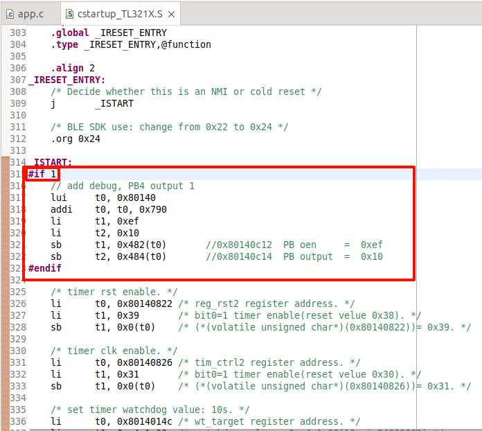
(2). Turn on the DEBUG_GPIO_ENABLE switch in app_config.h, this will enable the DEBUG IO before enabling the interrupt (irq_enable) operation. When this IO is high, it is the execution time point of the enable interrupt (irq_enable) operation;
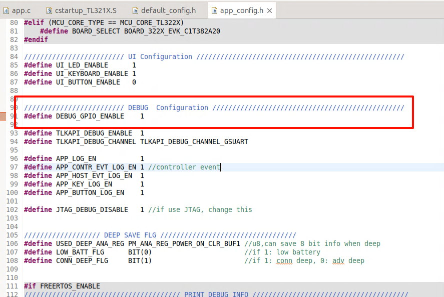
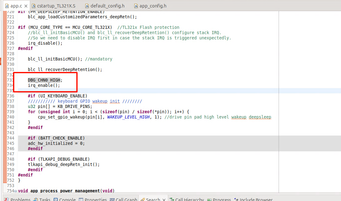
(3). Use the logic analyser to connect the above two IOs and set the chip into Deep Retention mode, you can observe the wake-up Time on the logic analyser's interface.

Set wake-up time plus a threshold of 50 us as a parameter via the blc_pm_setDeepsleepRetentionEarlyWakeupTiming API.
Issues in GPIO Wake-up
Fail to enter sleep mode when wake-up level is valid
In Telink MCU, GPIO wakeup is level triggered instead of edge triggered, so when GPIO PAD is configured as wakeup source, for example, suspend wakeup triggered by GPIO high level, MCU needs to make sure when MCU invokes cpu_sleep_wakeup to enter suspend, that the wakeup GPIO is not at high level. Otherwise, once entering cpu_sleep_wakeup, it would exit immediately and fail to enter suspend.
If the above situation occurs, it may cause unexpected problems, for example, it was intended to enter deepsleep and be woken up and the program re-executed, but it turns out that the MCU cannot enter deepsleep, resulting in the code continuing to run, not in the state we expected, and the whole flow of the program may be messed up.
User should pay attention to avoid this problem when using Telink's GPIO PAD to wake up.
If the APP layer does not avoid this problem, and GPIO PAD wakeup source is already effective at invoking of cpu_sleep_wakeup, PM driver makes some improvement to avoid flow mess:
(1) suspend & deepsleep retention mode
For both suspend and deepsleep retention mode, the SW will fast exit cpu_sleep_wakeup with two potential return values:
-
Return WAKEUP_STATUS_PAD if the PM module has detected effective GPIO PAD state.
-
Return STATUS_GPIO_ERR_NO_ENTER_PM if the PM module has not detected effective GPIO PAD state.
(2) deepsleep mode
For deepsleep mode, PM diver will reset MCU automatically in bottom layer (equivalent to watchdog reset). The SW restarts from "Run hardware bootloader".
Timer Wake-up by Application Layer
BLE task exists and without GPIO PAD wakeup, once MCU enters sleep mode, it only wakes up at T_wakeup pre-determined by SDK. User can not wake up MCU at an earlier time which might be needed at certain scenario. To provide more flexibility, application layer wakeup and associated callback function are added in the SDK:
Application layer wakeup API:
void blc_pm_setAppWakeupLowPower(u32 wakeup_tick, u8 enable);
"wakeup_tick" is wakeup time at System Timer tick value.
"enable": 1-wakeup is enabled; 0-wakeup is disabled.
Registered call back function blc_pm_registerAppWakeupLowPowerCb is executed at application layer wakeup:
typedef void (*pm_appWakeupLowPower_callback_t)(int);
pm_appWakeupLowPower_callback_t  pm_appWakeupLowPowerCb = NULL;
void blc_pm_registerAppWakeupLowPowerCb(pm_appWakeupLowPower_callback_t cb)
{
    pm_appWakeupLowPowerCb = cb;
}
Take Conn state Peripheral role as an example:
When the user uses blc_pm_setAppWakeupLowPower to set the app_wakeup_tick for the application layer to wake up regularly, the SDK will check whether app_wakeup_tick is before T_wakeup before entering sleep.
(1) If app_wakeup_tick is before T_wakeup, as shown in the figure below, it will trigger sleep in app_wakeup_tick to wake up early;
(2) If app_wakeup_tick is after T_wakeup, MCU will still wake up at T_wakeup.

Low Battery Detect
The battery power detect/check may also appear in Telink BLE SDK and related documents under other names, including: battery power detect/check, low battery detect/check, low power detect/check, battery detect/check, etc. For example, the SDK related files and functions may be named battery_check, battery_detect, battery_power_check, etc.
This document uniformly uses the name "low battery detect" for explanation.
Importance of Low Battery Detect
For battery-powered products, since the battery power will gradually decrease, when the voltage drops to a certain value, it will cause many problems:
a) The operating voltage range of tl_ble_sdk is 1.8V ~ 4.3V. When the voltage is lower than 1V, tl_ble_sdk can no longer guarantee stable operation.
b) When the battery voltage is low, due to the instability of the power supply, the "write" and "erase" operations of the Flash may have the risk of error, causing the program firmware and user data to be abnormally modified, and ultimately causing the product to fail. Based on previous mass production experience, we set this low voltage threshold that may cause risks to 2.0V.
According to the above description, battery-powered products must set a safe voltage value (secure voltage). Only when the voltage is higher than this secure voltage can the MCU continue to work; once the voltage is lower than the secure voltage, the MCU stops running and needs to be shut down immediately (implemented by entering deepsleep mode on the SDK).
The secure voltage is also called alarm voltage. The selection of this voltage value currently uses 2.0V by default in the SDK. If the user has an unreasonable design in the hardware circuit, resulting in the deterioration of the stability of the power supply network, the secure voltage value needs to be further increased, such as 2.1V, 2.2V, etc.
For products developed and implemented by Telink BLE SDK, as long as they are battery-powered, low-power detection must be a real-time task throughout the product life cycle to ensure product stability.
Implementation of Low Battery Detect
The low battery detect requires the use of ADC to measure the power supply voltage. Please refer to the relevant ADC chapters in the document of Datasheet and Driver SDK Developer Handbook, and first have a necessary understanding of the ADC module of tl_ble_sdk.
The implementation of low battery detect is explained in combination with the implementation given by the SDK demo "acl_central_demo", refer to the files battery_check.h and battery_check.c.
Make sure that the macro "BATT_CHECK_ENABLE" in the app_config.h file is enabled, and users need to pay attention when using the low power detection function.
##define BATT_CHECK_ENABLE 1
Notes on Low Battery Detect
The low battery detect is a basic ADC sampling task. When implementing ADC sampling of power supply voltage, there are some issues that need to be paid attention to, as explained below:
Use GPIO Input Channel
The sampling method of tl_ble_sdk can be VBAT or GPIO analog signal input, but the sampling accuracy of VBAT channel is poor. It is recommended to sample through external GPIO when high sampling accuracy is required.
The available GPIO input channels are the input channels corresponding to PB0 ~ PB7, PD0, and PD1.
typedef enum{
    ADC_GPIO_PB0 = GPIO_PB0 | (0x1<<12),
    ADC_GPIO_PB1 = GPIO_PB1 | (0x2<<12),
    ADC_GPIO_PB2 = GPIO_PB2 | (0x3<<12),
    ADC_GPIO_PB3 = GPIO_PB3 | (0x4<<12),
    ADC_GPIO_PB4 = GPIO_PB4 | (0x5<<12),
    ADC_GPIO_PB5 = GPIO_PB5 | (0x6<<12),
    ADC_GPIO_PB6 = GPIO_PB6 | (0x7<<12),
    ADC_GPIO_PB7 = GPIO_PB7 | (0x8<<12),
    ADC_GPIO_PD0 = GPIO_PD0 | (0x9<<12),
    ADC_GPIO_PD1 = GPIO_PD1 | (0xa<<12),
}adc_input_pin_def_e;
Use the GPIO input channel to perform ADC sampling of the power supply voltage. The specific usage is as follows: In the hardware circuit design, the power supply is directly connected to the GPIO input channel. When the ADC is initialized, the GPIO is set to high impedance (ie, oe, and output are all set to 0). At this time, the voltage on the GPIO is equal to the power supply voltage, and the ADC sampling can be performed directly.
The user can switch the GPIO input channel through the macro in app_config.h of "acl_central_demo":
//If using GPIO input channel, set this value to 0
##define VBAT_CHANNEL_EN                        1
In the demo, PB1 is selected as the GPIO input channel by default. PB1 is used as a normal GPIO function. During initialization, all states (ie, oe, output) use the default state without special modification. If the user wants to switch GPIO, he can select the GPIO input channel defined above and modify the following definition.
##define GPIO_BAT_DETECT                    GPIO_PB1
##define PB1_FUNC                       AS_GPIO
##define PB1_INPUT_ENABLE               0
##define PB1_DATA_OUT                   0
##define ADC_INPUT_PIN_CHN              ADC_GPIO_PB1
Use Differential Mode Only
Although the tl_ble_sdk ADC input mode supports both single-ended mode and differential mode, due to some specific reasons, Telink stipulates that only differential mode can be used, and single-ended mode is not allowed.
The input channel in differential mode is divided into positive input channel and negative input channel. The measured voltage value is the voltage difference obtained by subtracting the voltage of the negative input channel from the voltage of the positive input channel.
If there is only one input channel sampled by the ADC, when using differential mode, set the current input channel to the positive input channel and set GND to the negative input channel. In this way, the voltage difference between the two is equal to the voltage of the positive input channel.
The low battery detect in SDK uses differential mode, and the function interface is as follows:
adc_set_diff_input(ADC_INPUT_PIN_CHN >> 12, GND);
Different ADC Tasks Need to Be Switched
The low battery detect cannot run simultaneously with other ADC tasks and must be implemented using a switching method.
Separate Use of Low Battery Detect
In the SDK demo, the low battery detect function is implemented in the "acl_central_demo", "acl_connection_demo", and "acl_peripheral_demo" projects. The user needs to enable the low battery detect function in app_config.h to use it. If the user uses the low battery detect function in other feature_demos, refer to the definition of app_config.h in the implemented demo and the low battery detect related interface call logic in app.c.
Initialization of Low Battery Detect
Refer to the implementation of adc_bat_detect_init function.
The order of ADC initialization must meet the following process: first power off the SAR ADC, then configure other parameters, and finally power on the SAR ADC. All ADC sampling initializations must follow this process.
_attribute_ram_code_ void adc_bat_detect_init(void)
{
    adc_power_off();        // power off sar adc
    ......                  // add ADC Configuration
    adc_power_on();         // power on sar adc
}
For the sar adc power on and power off configuration, the user should try not to modify, just use these default settings. If the user selects a different GPIO input channel, modify the definition of the macros in app_config.h described above.
The code called by the adc_bat_detect_init initialization function in app_battery_power_check is:
if(!adc_hw_initialized){
    adc_hw_initialized = 1;
    adc_bat_detect_init();
}
Here, a variable adc_hw_initialized is used. Initialization is called once only when the variable is 0 and is set to 1. It is not initialized again when the variable is 1. The adc_hw_initialized will also be operated in the following API.
void battery_set_detect_enable (int en)
{
    lowBattDet_enable = en;
    if(!en){
        adc_hw_initialized = 0;   //need initialized again
    }
}
The functions that can be realized by the design using adc_hw_initialized are:
a) Switching with other ADC tasks ("ADC other task")
Ignoring the impact of sleep mode (suspend/deepsleep retention), only analyze the switching between low battery detect and other ADC tasks.
Because it is necessary to consider the switching between low battery detect and other ADC tasks, adc_bat_detect_init may need to be executed multiple times, it cannot be written to user initialization and must be implemented in main_loop.
When the app_battery_power_check function is executed for the first time, adc_bat_detect_init is executed and will not be executed repeatedly afterwards.
Once the "ADC other task" needs to be executed, the right to use the ADC will be taken away. Make sure that battery_set_detect_enable(0) must be called when the "ADC other task" is initialized, and adc_hw_initialized will be cleared to 0 at this time.
After the "ADC other task" is completed, the right to use the ADC is handed over. app_battery_power_check is executed again. Since the value of adc_hw_initialized is 0, adc_bat_detect_init must be executed again. This ensures that the low battery detect is reinitialized every time it is switched back.
b) Adaptive processing of suspend and deepsleep retention
Consider sleep mode.
The variable adc_hw_initialized must be defined as a variable in the "data" segment or "bss" segment, and cannot be defined on retention_data. Defining it in the "data" segment or "bss" ensures that this variable will be reinitialized to 0 when executing the software bootloader (i.e. cstartup_xxx.S) after each deepsleep retention wake_up; and this variable can remain unchanged after suspend wake_up.
The common characteristics of the registers configured in the adc_bat_detect_init function are: they will not be powered off in suspend mode and can save the state; they will be powered off in deepsleep retention mode.
If the MCU enters suspend mode and executes app_battery_power_check again after waking up, the value of adc_hw_initialized will be the same as before suspend, and there is no need to re-execute the adc_bat_detect_init function.
If the MCU enters deepsleep retention mode and adc_hw_initialized is 0 after waking up, adc_bat_detect_init must be re-executed and the ADC-related register status needs to be reconfigured.
The state of register set in adc_bat_detect_init function can keep power on during suspend.
The SDK adds the keyword "_attribute_ram_code_" to adc_bat_detect_init function to set it as ram_code, the ultimate goal is to optimize the power consumption of long sleep connection state. For example, for a typical 10ms * (99+1) = 1s long sleep connection, wake up once every 1s, and the long sleep in the middle uses deepsleep retention mode, then adc_bat_detect_init will be re-executed after each wake-up, and the execution speed will become faster after adding it to ram_code.
This "_attribute_ram_code_" is not required. In product applications, users can decide whether to put this function into ram_code based on the use of deepsleep retention area and the results of power consumption test.
Processing of Low Battery Detect
In main_loop, call the user_battery_power_check function to implement low battery detect. The relevant code is as follows:
##if (BATT_CHECK_ENABLE)
    /*The frequency of low battery detect is controlled by the variable lowBattDet_tick, which is executed every
     500ms in the demo. Users can modify this time according to their needs.*/
    if(battery_get_detect_enable() && clock_time_exceed(lowBattDet_tick, 500000) ){
        lowBattDet_tick = clock_time();
        user_battery_power_check(BAT_DEEP_THRESHOLD_MV);
    }
##endif
The battery_get_detect_enable() returns the value of lowBattDet_enable. The underlying low battery detect is enabled by default, that is, the value defaults to 1. If the user layer sets BATT_CHECK_ENABLE, the MCU can start low battery detect immediately after power-on. This variable needs to be set to retention_data to ensure that deepsleep retention cannot modify its state.
The value of lowBattDet_enable can only be changed by calling battery_set_detect_enable when other ADC tasks need to preempt the ADC usage rights: when other ADC tasks start, call battery_set_detect_enable(0), and the user_battery_power_check function will no longer be called in main_loop; after other ADC tasks are completed, call battery_set_detect_enable(1) to hand over the ADC usage rights, and the user_battery_power_check function can be called again in main_loop.
The variable lowBattDet_tick controls the frequency of low battery detection. In the demo, low battery detection is performed every 500ms. Users can modify this time value according to their needs.
The user_battery_power_check function is placed in ram_code. Refer to the above description of placing "adc_bat_detect_init" in ram_code, which is also to save running time and optimize power consumption.
This "attribute_ram_code" is not required. In product applications, users can decide whether to put this function in ram_code based on the use of deepsleep retention area and the results of power consumption test.
_attribute_ram_code_ void user_battery_power_check(u16 alarm_vol_mv);
Low Battery Alarm
The parameter of user_battery_power_check is the threshold voltage in mV. As mentioned above, the default setting of deepsleep in SDK is 2000mV. In the low voltage detection of main_loop, when the power supply voltage is lower than 2000mV, it enters deepsleep mode; when the power supply voltage is higher than 2200mV, it will wake up.
In the tl_ble_sdk demo, the method of entering deepsleep is used to shut down the MCU. Before entering sleep mode, an LED flashing prompt is set, and a button is set to wake up.
After the program is shut down, it enters deepsleep mode that can be woken up. At this time, if a button wakes up, the SDK will quickly perform a low battery detect during user initialization (user_init_normal()) instead of waiting until the detection in main_loop. The reason for this is to avoid application errors. An example is as follows:
When the key is triggered to wake up in the deepsleep state (the working voltage is still lower than the wake-up voltage), from the processing of main_loop, it takes at least 500ms to perform low battery detect, that is, the chip works abnormally for 500ms.
For this reason, the SDK must perform low battery detect in advance during user initialization, and must prevent the above situation from happening at this step. Therefore, add low battery detect during user initialization. The function interface in the SDK is:
##if (BATT_CHECK_ENABLE)
    user_battery_power_check(2000);
##endif
In the user_battery_power_check function, if the system is awakened from the deepsleep state, the threshold voltage for low battery detect is set as the parameter alarm_vol_mv+200mV. The main reason is that when the system is awakened from the shutdown mode, the alarm voltage is slightly increased during the fast low battery detect. The increase is slightly larger than the maximum error of the low battery detect. Therefore, it is necessary to set a higher voltage for the voltage detected during wake-up. Generally, the recovery voltage of 2200mV will only appear when the system enters the shutdown mode after a low battery detect is found to be lower than 2000mV. Therefore, the user does not need to worry that this 2200mV will falsely report low voltage for products with an actual voltage of 2V ~ 2.2V.
Low Battery Detect and Amic Audio
Refer to the detailed introduction in the low battery detect single use mode. For products that need to implement Amic Audio, just switch between low battery detect and Amic Audio.
According to the single use mode of low battery detect, after the program starts running, low battery detect is turned on by default. When Amic Audio is triggered, do the following two things:
(1) Disable low battery detect
Call battery_set_detect_enable(0) to inform the low battery detect module that the ADC resources have been preempted.
(2) Amic Audio ADC initialization
Since the ADC usage is different from low-battery detection, the ADC needs to be reinitialized. For specific methods, refer to the "Audio" section of this document.
When Amic Audio ends, call battery_set_detect_enable(1) to inform the low-battery detection module that the ADC resources have been released. At this time, the low-battery detection needs to reinitialize the ADC module and then start low-battery detection.
If low-battery detection and other non-Amic Audio ADC tasks exist at the same time, the processing of other ADC tasks can imitate the processing flow of Amic Audio.
If low-battery detection, Amic Audio, and other ADC tasks exist at the same time, the user can refer to the method of switching between low-battery detection and Amic Audio according to the principle of "ADC circuit needs to be switched".
Flash Protection
The Flash protection is mainly used to protect the user code, user data, and user configuration information in the Flash from being tampered with by unauthorized parties.
The Importance of Flash Protection
When the voltage is low or the power supply is unstable, there may be a risk of error in Flash operations (especially "write" and "erase" operations), causing abnormal modification of firmware and user data, and ultimately causing product failure. Based on previous mass production experience, it is recommended that customers enable Flash protection by default. When using Flash protection, we should set a security protection area size. On the one hand, it cannot affect the normal writing and erasing of protocol stack storage information (such as SMP information storage area), and on the other hand, it needs to protect programs and user data as much as possible.
For products developed with Telink BLE SDK, as long as they are battery powered, Flash protection is best to be enabled throughout the product life cycle to ensure product stability and user data security.
Enable Flash Protection
The Flash protection requires that the power supply voltage is greater than the safety voltage threshold. Therefore, when using the Flash protection function, the low voltage detection function must also be enabled.
The implementation of Flash protection is explained in conjunction with the implementation given by tl_ble_sdk/acl_central_demo, refer to the files flash_prot.h and flash_prot.c.
Make sure that the macro "APP_FLASH_PROTECTION_ENABLE" in the app_config.h file is enabled, and users need to pay attention when using the Flash protection function.
##define APP_FLASH_PROTECTION_ENABLE 1
Initialization of Flash Protection
The initialization calls the app_flash_protection_operation function. The first parameter is passed into the FLASH_OP_EVT_APP_INITIALIZATION event to indicate initialization of Flash protection. The initialization will not use the following two parameters, and 0 can be passed. The following is the initialization part of the app_flash_protection_operation function.
During the initialization of Flash protection, the sample code locks the area required for the OTA process by default (for B92, it is 000000h-07FFFFh 512KB space).
void app_flash_protection_operation(u8 flash_op_evt, u32 op_addr_begin, u32 op_addr_end)
{
    if(flash_op_evt == FLASH_OP_EVT_APP_INITIALIZATION) //Determine whether it is an initialization event
    {

        ////Read the mid information of Flash, determine which Flash it is based on the mid information and call the corresponding Flash lock API
        flash_protection_init();

        #if (BLE_OTA_SERVER_ENABLE)
            //If the OTA function is enabled, determine the Flash lock area based on the OTA startup address
            ......
        #else
            //Users can set the Flash lock area size according to actual conditions
            ......
        #endif

        //According to the size of the Flash lock area required by the upper layer, map it to commands on different Flash models and lock the Flash
        ......
    }

    ......
}
Note: For Flash areas that need to be modified, they must first be unlocked, and then locked again after modification. For example, after locking all Flash areas, if users need to erase and rewrite Flash, they must first unlock it. If users need to frequently operate on user data areas, they can consider locking only part of the area.
During initialization in the demo, the app_flash_protection_operation function will be registered as a callback function in the protocol stack, which will trigger different events for processing during the OTA process, mainly clearing the old firmware and writing the new firmware.
blc_appRegisterStackFlashOperationCallback(app_flash_protection_operation);
Processing of Flash Protection
In Telink BLE SDK, the Flash protection is handled in the app_flash_protection_operation function, including all Flash locks and unlocks in the application. If the user has more flash operations, it is recommended to add them in this function. The app_flash_protection_operation function is introduced below:
void app_flash_protection_operation(u8 flash_op_evt, u32 op_addr_begin, u32 op_addr_end)
{
    ......

    else if(flash_op_evt == FLASH_OP_EVT_STACK_OTA_CLEAR_OLD_FW_BEGIN)
    {   //OTA clear old firmware start event
        ......
    }
    else if(flash_op_evt == FLASH_OP_EVT_STACK_OTA_CLEAR_OLD_FW_END)
    {
        //OTA clear old firmware end event
        ......
    }
    else if(flash_op_evt == FLASH_OP_EVT_STACK_OTA_WRITE_NEW_FW_BEGIN)
    {
        //OTA write new firmware start event
        ......
    }
    else if(flash_op_evt == FLASH_OP_EVT_STACK_OTA_WRITE_NEW_FW_END)
    {
        //OTA write new firmware end event
        ......
    }
    //If the user application needs to add more Flash protection operations, you can continue to add them later.
}
The parameter op_addr_begin indicates the starting address of the Flash protection area.
The parameter op_addr_end indicates the ending address of the Flash protection area.
The parameter flash_op_evt indicates the event of Flash protection, including application layer actions and protocol stack events (OTA write and erase), including 5 events in total:
##define FLASH_OP_EVT_APP_INITIALIZATION                        1

##define FLASH_OP_EVT_STACK_OTA_CLEAR_OLD_FW_BEGIN          10

##define FLASH_OP_EVT_STACK_OTA_CLEAR_OLD_FW_END                11

##define FLASH_OP_EVT_STACK_OTA_WRITE_NEW_FW_BEGIN          12

##define FLASH_OP_EVT_STACK_OTA_WRITE_NEW_FW_END                13
(1) FLASH_OP_EVT_APP_INITIALIZATION is the Flash protection initialization event, which locks the Flash.
(2) FLASH_OP_EVT_STACK_OTA_CLEAR_OLD_FW_BEGIN is the start event of OTA clearing old firmware, and the Flash needs to be unlocked. The OTA clear old firmware start event is triggered by the protocol stack bottom layer, in "blc_ota_initOtaServer_module", during the chip restart phase after the OTA is successful. The software will erase the entire old firmware in preparation for the next new OTA process. If any part of the memory address from "op_addr_begin" to "op_addr_end" is in the locked area, the Flash needs to be unlocked. In the demo sample code, we protect the entire Flash area for the new and old firmware, so here we do not need to judge "op_addr_begin" and "op_addr_end", and the Flash must be unlocked.
(3) FLASH_OP_EVT_STACK_OTA_CLEAR_OLD_FW_END is the end event of OTA clearing the old firmware, and the Flash needs to be locked. The end event of OTA clearing the old firmware is triggered by the stack. In "blc_OTA_initOtaServer_module", the old firmware data is erased. The "op_addr_begin" and "op_addr_end" are ignored in the end event. In the demo sample code, we need to lock the Flash again because we have unlocked it at the start event of clearing the old firmware.
(4) FLASH_OP_EVT_STACK_OTA_WRITE_NEW_FW_BEGIN is the start event of OTA writing new firmware, and the Flash needs to be unlocked. When the first OTA data PDU is received, the OTA write new firmware start event is triggered by the stack, and the software writes the data to the Flash area where the new firmware is stored. If any part of the Flash address from "op_addr_begin" to "op_addr_end" is in the locked area, Flash unlocking is required. In the demo sample code, we have protected the entire Flash area for the new and old firmware, so here we do not need to judge "op_addr_begin" and "op_addr_end", and directly unlock the Flash.
(5) FLASH_OP_EVT_STACK_OTA_WRITE_NEW_FW_END is the end event of OTA writing new firmware, and the Flash needs to be locked. The end event of OTA writing new firmware is triggered by the stack, after the OTA ends, an OTA error occurs, or the writing of new firmware data is completed. Ignore "op_addr_begin" and "op_addr_end" in the end event. In the demo sample code, we need to lock the Flash again because we have unlocked it when writing the start event of the new firmware.
In the SDK demo, the Flash protection part only involves the writing and erasing of new and old programs during the OTA process. Users can add other events to perform Flash write protection operations according to the application situation.
Currently, the code logic only provides protection to the fixed address space, and the op_addr_begin and op_addr_end parameters are currently invalid. To facilitate customer use, the logic for using these parameters will be added in the future.
Lock and Unlock Operation
//Lock function, flash_lock_cmd controls the lock area. Take B92 as an example. For the complete definition, refer to mid156085_lock_block_e in flash_mid156085.h
void flash_lock(unsigned int flash_lock_cmd)

//unlock function
void flash_unlock(void)
The Flash protection only supports protection of a specific, continuous area. If the new locked area is different from the old locked area during the lock function, the unlock operation of the old locked area is first performed, and then the new locked area is locked.
During use, users can directly call the lock and unlock functions for operation, but for the convenience of code management, it is recommended to only call app_flash_protection_operation for operation:
1) Customize the opcode in flash_port.h
2) Write the corresponding operation logic in the app_flash_protection_operation function in combination with the opcode judgment.
OTA
The tl_ble_sdk supports the device to upgrade as OTA Server or OTA Client, by default Peripheral is used as OTA Server, Central is used as OTA Client. Only one OTA is allowed on one Peripheral link at the same moment.
The reference code for OTA Client can be found in feature_ota. The implementation code for OTA Server is in the protocol stack and is not open.
The tl_ble_sdk supports Flash multi-address booting: besides the first address of Flash address 0x00000, it also supports reading firmware running from Flash high address 0x20000 (128K), 0x40000 (256K), 0x80000 (512K). This document uses high address 0x20000 as an example to introduce OTA.
Flash Storage Architecture
Flash storage architecture is divided into traditional architecture (when Secure Boot function is not enabled) and Secure Boot architecture (when Secure Boot function is enabled). In both architectures, if users use the boot address 0x20000, the firmware size compiled by SDK should not be larger than 128K, i.e., the area between 0~0x20000 of Flash stores Firmware_1, but due to some special reasons, if users use the boot address of 0 and 0x20000 alternately for OTA upgrade, its firmware size must not exceed 124K (the last 4KB of the high address space can not be used); if it exceeds 124K, users must use boot address 0 and 0x40000 to upgrade alternatively, at this time the maximum firmware size must not exceed 252K, if it exceeds 252K users must use boot address 0 and 0x80000 to upgrade alternatively, at this time the maximum firmware size must not exceed 508K.
Secure Boot related instructions please refer to:Secure Boot Application Note
Traditional Storage Architecture

(1) OTA Client burns new firmware_2 to the area 0x20000~0x40000.
(2) The 1st OTA:
-
Server boots from the read program in the 0~0x20000 area of the flash at power on and runs firmware_1;
-
When firmware_1 is running, the 0x20000~0x40000 area is cleared during initialization, which will be used as the storage area for the new firmware.
-
The OTA is started and the Client transfers firmware_2 to the 0x20000~0x40000 area of the Server via Bluetooth interaction. After successful upgrade, Server reboots.
(3) The new firmware_3 is burned to the area 0x20000~0x40000 of OTA Client.
(4) The 2nd OTA:
-
Server boots from the read program in the 0x20000~0x40000 area of the flash at power on and runs firmware_2;
-
When firmware_2 is run, the 0~0x20000 area is cleared during initialization, which will be used as the storage area for the new firmware.
-
The OTA is started and the Client transfers firmware_3 to the 0~0x20000 area of the Server via over-the-air package. After successful upgrade, Server reboots.
(5) The later OTA process repeats the above (1) ~ (4) process, which can be interpreted as (2) represents the (2n+1)-th OTA and (3) represents the (2n+2)-th OTA.
Note
- If the B92 chip enables firmware Encryption, the software must call the following interface to configure the Secure Boot OTA function, otherwise normal firmware Encryption OTA cannot be performed.
ble_sts_t blc_ota_enableFirmwareEncryption(void);
Secure Boot Storage Architecture
If the Secure Boot function is used, the OTA module needs to refer to feature_test/feature_ota for special design. As the Client, defines it in feature_ota/app_config:
##define OTA_CLIENT_SEND_SECURE_BOOT_SIGNATURE_ENABLE 1
The Client sends the public key and signature described in the Secure Boot section of the Secure Boot Application Note to the Server, allowing the Server to perform the relevant verification process.
As the Server, defines it in feature_ota/app_config:
##define APP_HW_FIRMWARE_ENCRYPTION_ENABLE 1
The initialization process will call the API blc_ota_enableFirmwareEncryption to enable firmware encryption. The MCU automatically completes the encryption and decryption process when reading / writing Flash. The function corresponds to the firmware Encryption section in the Secure Boot Application Note.
Defines it in feature_ota/app_config:
##define APP_HW_SECURE_BOOT_ENABLE 1
The initialization process will call the API blc_ota_enableSecureBoot to enable Secure Boot. The MCU will add a firmware verification process during the power-on and OTA process to ensure that the program is not tampered with. The function corresponds to the Secure Boot section in the Secure Boot Application Note.
When the chip enables Secure Boot, the software must call the following interface to configure the Secure Boot OTA function, otherwise normal Secure Boot OTA cannot be performed.
ble_sts_t blc_ota_enableSecureBoot(void);

The following is an example of 1MB Flash. The default descriptor locations in 1MB Flash are 0xF8000 and 0xFA000, each descriptor occupies 8kB of space.
(1) OTA Client burns the new firmware_2 and descriptors to the areas 0x20000~0x40000, 0x60000 respectively.
(2) The 1st OTA:
-
Server reads the address parameter of the program from the descriptor address 0xF8000 of flash when it is powered on (the figure takes the descriptor in 0xF8000 corresponding to the program address 0x00000 as an example);
-
Server boots from the read program in the corresponding 0x00000 area and runs firmware_1;
-
When firmware_1 is running, during the initialization, the program area in 0x20000~0x40000 and another descriptor area 0xFA000~0xFC000 are cleared, and these two areas will be used as storage for the new firmware and the new descriptor, respectively.
-
OTA is started and Client transfers firmware_2 and descriptors to 0x20000~0x40000 and 0xFA000 area of Server via Bluetooth. After successful upgrade, Server reboots.
(3) The new firmware_3 is burned to the 0x20000~0x40000 area of OTA Client.
(4) The 2nd OTA:
-
Server reads the address parameter of the program from the descriptor address 0xFA000 of flash when it is powered on (the figure takes the descriptor in 0xFA000 corresponding to the program address 0x20000 as an example);
-
Server boots from the read program in the corresponding 0x20000 area and runs firmware_2;
-
When firmware_2 is running, during the initialization, the program area in 0x00000~0x20000 and another descriptor area 0xFA000~0xFC000 are cleared, and these two areas will be used as storage for the new firmware and the new descriptor, respectively.
-
OTA is started and Client transfers firmware_3, descriptors to 0x00000~0x20000, 0xF8000 area of Server via Bluetooth. After successful upgrade, Server reboots.
(5) The later OTA process repeats the above (1) ~ (4) process, which can be interpreted as (2) represents the (2n+1)-th OTA and (3) represents the (2n+2)-th OTA.
OTA Update Process
Based on the above Flash storage architecture, the OTA program update process is explained in detail. Corresponding to the Flash storage architecture, the OTA update process is divided into traditional process and Secure Boot process.
At first, the following introduces the traditional process.
Traditional OTA Update Process
Taking the high address 0x20000 as an example, when MCU is powered on, MCU starts from the 0 address by default, and first reads the content of Flash 0x20. If the value is 0x544C4E4B, MCU starts to move the code to RAM from address 0, and all the next fetch values start from address 0, i.e., fetch value address = 0 + the value of the PC pointer; if the value of 0x20 is not 0x544C4E4B, the MCU directly reads the value of 0x20020, if the value is 0x544C4E4B, MCU starts to move the code to RAM from address 0x20000, and all the next fetch values start from address 0x20000, i.e., fetch value address = 0x20000 + the value of the PC pointer.
Thus, just modify the value of the 0x20 and 0x20020 flag bits to specify which part of the FLASH code is executed by the MCU.
A certain (2n+1 or 2n+2) power-on and OTA process of the SDK is:
(1) After the MCU is powered on, the start address is determined by reading the values of 0x20 and 0x20020 and comparing them with 0x544C4E4B, then the code is started and executed from the corresponding address. This function is done automatically by the MCU hardware.
(2) During program initialization, the address from which the MCU is started is determined by reading the MCU hardware registers:
If the MCU starts from 0, ota_program_offset is set to 0x20000 and all non-0xff contents of the 0x20000 area are erased to 0xff, indicating that the new firmware obtained by the next OTA will be stored in the area starting at 0x20000;
If the MCU starts from 0x20000, ota_program_offset is set to 0x0 and all non-0xff contents of the 0x0 area are erased to 0xff, indicating that the new firmware obtained by the next OTA will be stored in the area starting at 0x0.
(3) The Server program runs normally, the OTA Client runs after powering on, and both of them establish BLE connection.
(4) On the OTA Client side, OTA Client is triggered into OTA mode via the UI (it can be a key, PC tool to write memory, etc.) After the OTA Client enters the OTA mode, it first needs to get the value of the Attribute Handle of the OTA service data Attribute on the Server side.
(5) After OTA Client obtains the value of Attribute Handle of OTA service data Attribute on Server side, it obtains the current version number of firmware on Server side.
Note
- If legacy protocol is used, users need to realize it by themselves to get the version number; if extend protocol is used, the operation related to getting the version number is already realized. For the difference between legacy and extend protocol, users can refer to the RF-Transfer Processing Method.
(6) After the Client determines that it wants to do an OTA update, it first sends an OTA_start command to notify the Server to enter OTA mode.
(7) After Server receives the OTA_start command, it enters OTA mode and waits for Client to send OTA data.
(8) Client reads the pre-stored firmware from the area starting from 0x20000 and sends OTA data to Server continuously until the whole firmware is sent.
(9) Server receives the OTA data and stores it in the area starting from ota_program_offset.
(10) After the Client sends all the OTA data, it checks whether all these data are correctly received by the Server (calling the relevant function of the underlying BLE to determine whether the data in the link layer are correctly acked).
(11) After the Client determines that all OTA data has been correctly received by the Server, it sends an OTA_END command.
(12) After Server receives the OTA_END command, it writes the new firmware area offset address 0x20 (i.e., ota_program_offset+0x20) to 0x544C4E4B, and rewrites the old firmware storage area offset address 0x20 to 0x00000000, which indicates that the next program is started, it will move the code from the new area to execute.
(13) Server reports the result of OTA to Client through Handle Value Notification.
(14) Server is rebooted and the new firmware takes effect.
During the whole OTA update process, Server will keep checking whether there are wrong packets and packet loss, and also keep checking whether there is timeout (a timer is activated at the beginning of the OTA). Once there are wrong packets, packet loss or timeout, Server will consider that the update fails, and send the reason of failure to the other side to use the previous firmware.
In the above process, Server side related operations have been implemented in the SDK, the user does not need to add anything, the Client side requires additional programming, which will be described in detail later.
Secure Boot OTA Update Process
First of all the multi-address boot mechanism in Secure Boot is (1MB Flash as an example, the two descriptors correspond to the first two boot addresses 0x00000 and 0x20000 respectively): After the MCU is powered on, it reads descriptors from 0xF8000 by default, firstly reads the content of flash 0xF8000, if the value is 0x544C4E4B and the descriptor content passes checking, then it moves the code to RAM from address 0, and all the next fetch values start from address 0, i.e., fetch values address = 0 + PC pointer; if the value of 0xF8000 is not 0x544C4E4B, the MCU directly reads the value of 0xFA000. If the value of 0xFA000 is 0x544C4E4B and the descriptors content passes checking, the MCU moves the code to RAM starting from 0x20000 and all the next fetch values start from the 0x20000 address, i.e., fetch values address = 0x20000 + the value of the PC pointer.
Thus, modify the value of the 0xF8000 and 0xFA000 flag bits to specify which part of the FLASH code is executed by the MCU.
A certain (2n+1 or 2n+2) power-on and OTA process of the SDK is:
(1) After the MCU is powered on, by reading the values of 0xF8000 and 0xFA000 and comparing them with 0x544C4E4B, it determines the starts address, and completes the program checking. Then it starts and executes the code from the corresponding address. This function is done automatically by MCU hardware.
(2) During program initialization, the address from which the MCU is started is determined by reading the MCU hardware registers:
If the MCU starts from 0, ota_program_offset is set to 0x20000 and all non-0xff contents of the 0x20000 area are erased to 0xff, indicating that the new firmware obtained by the next OTA will be stored in the area starting at 0x20000;
If the MCU starts from 0x20000, ota_program_offset is set to 0x0 and all non-0xff contents of the 0x0 area are erased to 0xff, indicating that the new firmware obtained by the next OTA will be stored in the area starting at 0x0.
(3) The Server program runs normally, the OTA Client runs after powering on and establishes a BLE connection to the Server.
(4) On the OTA Client side, OTA Client is triggered into OTA mode via the UI (it can be a key, PC tool to write memory, etc.). After the OTA Client enters the OTA mode, it first needs to get the Attribute Handle value of the OTA service data Attribute on the Server side.
(5) After OTA Client obtains the Attribute Handle value of the Server OTA service data Attribute, it obtains the firmware version number of the current Server FLASH program.
Note
- If legacy protocol is used, users need to realize it by themselves to get the version number; if extend protocol is used, the operation related to getting the version number is already realized. For the difference between legacy and extend protocol, users can refer to the section 7.3.2.
(6) After the Client determines that it wants to do an OTA update, it first sends an OTA_start command to notify the Server to enter OTA mode.
(7) After Server receives the OTA_start command, it enters OTA mode and waits for Client to send OTA data.
(8) Client reads the pre-stored descriptor from the area starting at 0x60000 and sends the public key and signature in the descriptor to Server.
(9) After Server receives the public key and signature, it will check the public key, if the checking fails, it will exit the OTA; if the checking succeeds, it will write the public key, signature, new firmware running address information, etc. to the corresponding location in the new descriptor area.
(10) Client reads the pre-stored firmware from the area starting from 0x20000 and sends OTA data to Server continuously until the whole firmware is sent.
(11) Server receives the OTA data and stores it in the area starting from ota_program_offset.
(12) After the Client sends all the OTA data, it checks whether all these data are correctly received by the Server (calling the relevant function of the lower-level BLE to determine whether the data in the link layer are correctly acked).
(13) After the Client determines that all OTA data has been correctly received by the Server, it sends an OTA_END command.
(14) After Server receives the OTA_END command, it verifies the new firmware, and after the verification passes, it writes the new descriptor storage area offset address 0x0 to 0x544C4E4B, and rewrites the old descriptor storage area offset address 0x0 to 0x00000000, indicating that it will be read and executed from the new descriptor area after the next program start.
(15) Server reports the result of OTA to Client through Handle Value Notification.
(16) Server is rebooted and the new firmware takes effect.
During the whole OTA update process, Server will keep checking whether there are wrong packets, packet loss, timeout (a timer is activated at the beginning of the OTA), and it also checks whether there are public key errors, signature verification errors. Once there are wrong packets, packet loss, public key errors, signature verification errors or timeout, Server will consider that the update fails, and send the reason of failure to the other side to use the previous firmware.
In the above process Server side of the relevant operations have been implemented on the SDK, the user does not need to add anything, the Client side requires additional programming, which will be described in detail later.
Modify Firmware Size and Boot Address
The API blc_ota_setFirmwareSizeAndBootAddress supports the modification of the boot address. This boot address refers to another address in the OTA design where the New_firmware is stored in addition to the 0 address (which can only be 0x20000, 0x40000 or 0x80000).
| Firmware_Boot_address | Firmware size (max)/K |
|---|---|
| 0x20000 | 124 |
| 0x40000 | 252 |
| 0x80000 | 508 |
The default maximum firmware size in the SDK is 252K (due to some special reasons, the firmware size of the boot address 0x40000 shall not be larger than 252K), the corresponding boot address is 0x00000 and 0x40000. These two values are consistent with the description in the previous section, users need to follow the constraint relationship between boot address and firmware_size size in Table 7-1 when setting. If the maximum firmware_size is changed and exceeds 124K, in this case users need to move the boot address to 0x40000 (size maximum must not exceed 252K), similarly if firmware_size exceeds 252K, users need to move the boot address to 0x80000 (size maximum must not exceed 508K). For example, the maximum firmware size may be up to 200K , users can call API blc_ota_setFirmwareSizeAndBootAddress to set:
ble_sts_t blc_ota_setFirmwareSizeAndBootAddress(int firmware_size_k, multi_boot_addr_e boot_addr);
Note
- This API must be called before the sys_init function.
The parameter multi_boot_addr_e indicates the available boot address, and there are three options in total:
typedef enum{
    MULTI_BOOT_ADDR_0x20000     = 0x20000,  //128 K
    MULTI_BOOT_ADDR_0x40000     = 0x40000,  //256 K
    MULTI_BOOT_ADDR_0x80000     = 0x80000,  //512 K
};
The return value ble_sts_t indicates the state of the setting, refer to ble_common.h in the SDK for the definition of this type.
Returns BLE_SUCCESS if successful; otherwise returns SERVICE_ERR_INVALID_PARAMETER.
OTA Mode RF Data Processing
OTA Processing in Attribute Table
The Server side adds the OTA related content in the Attribute Table, where the parameter w in att_readwrite_callback_t of OTA Data Attribute is set to otaWrite, and the attributes are set to Read and Write_without_Rsp. OTA Client uses Write Command to send data by default, no need for Server to return ack (the speed will be faster). If Client uses Write Request to send data, it is necessary to change the gatt's feature permission to allow Server side response (CHAR_PROP_WRITE_WITHOUT_RSP is changed to CHAR_PROP_WRITE).
// OTA attribute values
static const u8 my_OtaCharVal[19] = {
    CHAR_PROP_READ | CHAR_PROP_WRITE_WITHOUT_RSP,
    U16_LO(OTA_CMD_OUT_DP_H), U16_HI(OTA_CMD_OUT_DP_H),
    TELINK_SPP_DATA_OTA, };

    {5,ATT_PERMISSIONS_READ, 2,16,(u8*)(&my_primaryServiceUUID),    (u8*)(&my_OtaServiceUUID), 0},
    {0,ATT_PERMISSIONS_READ, 2, sizeof(my_OtaCharVal),(u8*)(&my_characterUUID), (u8*)(my_OtaCharVal), 0},               //prop
    {0,ATT_PERMISSIONS_RDWR,16,sizeof(my_OtaData),(u8*)(&my_OtaUUID),   (&my_OtaData), &otaWrite, NULL},            //value
    {0,ATT_PERMISSIONS_RDWR,2,sizeof(otaDataCCC),(u8*)(&clientCharacterCfgUUID),    (u8*)(otaDataCCC), 0},
    {0,ATT_PERMISSIONS_READ, 2,sizeof (my_OtaName),(u8*)(&userdesc_UUID), (u8*)(my_OtaName), 0},
When Client sends OTA data to Server, it actually writes data to the third Attribute above, and Client needs to know the Attribute Handle of this Attribute in the whole Attribute Table.
OTA Protocol
The current OTA architecture has been extended with functionality and is compatible with previous versions of the protocol. The entire OTA protocol consists of two parts: the Legacy protocol and the Extend protocol:
| OTA Protocol | - |
|---|---|
| Legacy protocol | Extend protocol |
Note
- Functions supported by OTA protocol:
(1) OTA Result feedback function: This function is not optional, it is added by default;
(2) FirmWare Version Compare function and Big PDU function: This function is optional, it can not be added. It is necessary to pay attention to a point in which the version number comparison function in the Legacy protocol and Extend protocol in the realization of the difference, specific reference to the following OTA_CMD section.
The following introduction focuses on the Legacy and Extended protocols.
OTA_CMD composition
The PDU of OTA's CMD is as follows:
| OTA Command Payload | - |
|---|---|
| Opcode (2 octet) | Cmd_data (0-18 octet) |
Opcode
| Opcode | Name | Use* |
|---|---|---|
| 0xFF00 | CMD_OTA_VERSION | Legacy |
| 0xFF01 | CMD_OTA_START | Legacy |
| 0xFF02 | CMD_OTA_END | All |
| 0xFF03 | CMD_OTA_START_EXT | Extend |
| 0xFF04 | CMD_OTA_FW_VERSION_REQ | Extend |
| 0xFF05 | CMD_OTA_FW_VERSION_RSP | Extend |
| 0xFF06 | CMD_OTA_RESULT | All |
| 0xFF10~0xFF17 | CMD_OTA_SB_PUBKEY_SIGN | All |
Note
- Use: It is recognized as a command that can be used in Legacy protocol, Extend protocol, or both;
- Legacy: It is only used in Legacy protocol;
- Extend: it is only used in Extend protocol;
- All: It is available in both Legacy protocol and Extend protocol.
- CMD_OTA_SB_PUBKEY_SIGN: it is used only when Secure Boot is enabled.
(1) CMD_OTA_VERSION
This command is the command to get the current firmware version number of Server, and users can choose to use it if they adopt OTA Legacy protocol for OTA upgrade. When using this command, the firmware version number can be passed through the callback function reserved on the Server side.
void blc_ota_registerOtaFirmwareVersionReqCb(ota_versionCb_t cb);
This callback function is triggered when the Server side receives the CMD_OTA_VERSION command.
(2) CMD_OTA_START
This command is the OTA update start command, Client sends this command to Server to officially start OTA update. This command is used only for Legacy Protocol, and users must use this command if they adopt OTA Legacy protocol.
(3) CMD_OTA_END
This command is the end command, which is used by both legacy and extend protocols in OTA. When the Client determines that all OTA data have been correctly received by the Server, it sends the OTA end command. In order for the Server to determine again that it has fully received all the data from the Client (double check, as a way to ensure correctness), the OTA end command is followed by four valid bytes, which are described in detail later.
| - | CMD_data | - |
|---|---|---|
| Adr_index_max (2 octets) | Adr_index_max_xor (2 octets) | Reserved (16 octets) |
-
Adr_index_max: Maximum value of adr_index.
-
Adr_index_max_xor: Adr_index_max exclusive or value to be used for checking.
-
Reserved: Reserved for future expansions.
(4) CMD_OTA_START_EXT
This command is the OTA update start command in the extend protocol. The Client sends this command to the Server to officially start the OTA update. If users use OTA extend protocol, they must use this command as the start command.
| - | CMD_data | - |
|---|---|---|
| Length (1 octets) | Version_compare (1 octets) | Reserved (16 octets) |
-
Length: PDU length.
-
Version_compare: 0x01: Enable version compare function; 0x00: Disable version compare function.
-
Reserved: Reserved for future expansions.
(5) CMD_OTA_FW_VERSION_REQ
This command is a version comparison request during the OTA upgrade process. It is initiated by the Client to the Server, requesting the version number and upgrade permission.
| - | CMD_data | - |
|---|---|---|
| version_num (2 octets) | version_compare (1 octets) | Reserved (16 octets) |
-
Version_num: Firmware version number to be upgraded on the Client side.
-
Version_compare: 0x01: Enable version compare function; 0x00: Disable version compare function.
-
Reserved: Reserved for future expansions.
(6) CMD_OTA_FW_VERSION_RSP
This command is a version response command. After receiving the version comparison request command (CMD_OTA_FW_VERSION_REQ) from the Client, the Server side compares the existing firmware version number with the version number requested by the Client side for upgrading to determine whether to upgrade or not, and the related information is sent to the Client through this command.
| - | CMD_data | - |
|---|---|---|
| version_num (2 octets) | version_accept (1 octets) | Reserved (16 octets) |
-
Version_num: The version number of the firmware currently running on the Server side.
-
Version_accept: 0x01: Accept Client upgrade request; 0x00: Reject Client upgrade request.
-
Reserved: Reserved for future expansions.
(7) CMD_OTA_SB_PUBKEY_SIGN
This command is a public key and signature transmission command. After receiving the version of the public key and signature transmission command (CMD_OTA_SB_PUBKEY_SIGN) from Client, Server will compare the existing public key with the public key sent by Client to determine whether OTA is allowed. The command is sent in a total of 8 packets of 16 bytes each.
| CMD_data |
|---|
| data (16 octets) |
(8) CMD_OTA_RESULT
This command is the OTA result return command. After the OTA is finished, Server will send the result information to Client, in the whole OTA process, no matter success or failure, OTA_result will only be reported once, and users can determine whether the upgrade is successful or not according to the returned result.
| CMD_data | - |
|---|---|
| Result (1 octets) | Reserved (16 octets) |
Result: OTA result information, all possible return results are shown in the following table:
Table: OTA all possible return results
Value Type info
0x00 OTA_SUCCESS success
0x01 OTA_DATA_PACKET_ OTA data packet sequence number error: repeated OTA PDU or lost some OTA PDU SEQ_ERR
0x02 OTA_PACKET_INVALID invalid OTA packet: 1. invalid OTA command; 2. addr_index out of range; 3.not standard OTA PDU length
0x03 OTA_DATA_CRC_ERR packet PDU CRC err
0x04 OTA_WRITE_FLASH_ERR write OTA data to flash ERR
0x05 OTA_DATA_INCOMPLETE lost last one or more OTA PDU
0x06 OTA_FLOW_ERR peer device send OTA command or OTA data not in correct flow
0x07 OTA_FW_CHECK_ERR firmware CRC check error
0x08 OTA_VERSION_ the version number to be update is lower than the current version COMPARE_ERR
0x09 OTA_PDU_LEN_ERR PDU length error: not 16*n, or not equal to the value it declare in "CMD_OTA_START_EXT" packet
0x0a OTA_FIRMWARE_ firmware mark error: not generated by telink's BLE SDK MARK_ERR
0x0b OTA_FW_SIZE_ERR firmware size error: no firmware_size; firmware size too small or too big
0x0c OTA_DATA_PACKET_ time interval between two consequent packet exceed a value(user can adjust this value) TIMEOUT
0x0d OTA_TIMEOUT OTA flow total timeout
0x0e OTA_FAIL_DUE_TO_ OTA fail due to current connection terminate(maybe connection timeout or local/peer device terminate connection) CONNECTION _TERMIANTE
0x0f OTA_MCU_NOT MCU does not support this OTA mode _SUPPORTED
0x10 OTA_LOGIC_ERR software logic error, please contact FAE of Telink
0x80 OTA_SECBOOT_HW_ERR OTA server device hardware error
0x81 OTA_SECBOOT OTA server device system error _SYSTEM_ERR
0x82 OTA_SECBOOT_FUNC OTA server device do not enable secure boot function _NOT_ENABLE
0x83 OTA_SECBOOT_PUBKEY OTA public key & signature sequence number error: repeated or lost _SIGN_SEQ_ERR
0x84 OTA_SECBOOT_PUBKEY OTA public key & signature data packet length error _SIGN_LEN_ERR
0x85 OTA_SECBOOT_PUBLIC OTA client public key not match OTA server device local hash _KEY_ERR
0x86 OTA_SECBOOT_SIGN OTA signature verification fail _VERIFY_FAIL
0x87 OTA_SECBOOT_WRITE write secure boot descriptor fail _DESC_FAIL
0x88 OTA_SECBOOT_NEW_FW secure boot function: new firmware not match old firmware _NOT_MATCH_OLD_FW 1. old firmware enable secure boot, but new firmware do not enable 2. old firmware do not enable secure boot, but new firmware enable
0x89 OTA_FWENC_NEW_FW firmware encryption function: new firmware not match old firmware _NOT_MATCH_OLD_FW 1. old firmware enable firmware encryption, but new firmware do not enable 2. old firmware do not enable firmware encryption, but new firmware enable
Other Reserved for future use /
Note
- 0x80~0x89 are only applicable in Secure Boot mode.
OTA Packet structural components:
When the Client uses Write Command or Write Request to send commands and data to the Server, the value of the ATT layer related Attribute Handle is the handle_value of the OTA data on the Server side. According to the BLE Spec L2CAP layer specification on PDU format, the Attribute Value length is defined as the OTA_DataSize field of the following figure.

-
DLE Size: CID + Opcode + Att_Handle + Adr_index + OTA_PDU + CRC
-
MTU_Size: Opcode + Att_Handle + Adr_index + OTA_PDU +CRC
-
OTA_Data_Size: Adr_index + OTA_PDU + CRC
Introduction of OTA_Data:
| Type | Length |
|---|---|
| Default + BigPDU | 16octets -240octets(n*16,n=1..15) |
Note
- Default: the OTA PDU length is fixed, the default size is 16 octets.
- BigPDU: the OTA PDU length can be changed in the range of 16 octets - 240 octets and is an integer multiple of 16 bytes.
OTA_PDU Format:
When users adopt Extend protocol in OTA, which supports Big PDU, it can support long packet for OTA upgrade operation and reduce the time of OTA upgrade, and users can customize the size of PDU on Client side according to their needs. The last two bytes are the values of the first CRC obtained by performing a CRC_16 calculation on the previous Adr_Index and Data. When Server receives the OTA data, it will perform the same CRC calculation, and only if the CRC calculated by both matches, it will be considered as a valid data.
| - | OTA PDU | - |
|---|---|---|
| Adr_Index (2 octets) | Data(n*16 octets) n=1..15 | CRC (2 octets) |
(1) PDU packet length: n = 1;
Data: 16 octets;
Mapping relationship between Adr_Index and firmware address:
| Adr_Index | Firmware_address |
|---|---|
| 0x0001 | 0x0000 - 0x000F |
| 0x0002 | 0x0010 - 0x001F |
| ……. | …… |
| XXXX | (XXXX -1)*16 - (XXXX)*16+15 |
(2) PDU packet length: n = 2;
Data: 32 octets;
Mapping relationship between Adr_Index and firmware address:
| Adr_Index | Firmware_address |
|---|---|
| 0x0001 | 0x0000 - 0x001F |
| 0x0002 | 0x0010 - 0x003F |
| …… | …… |
| XXXX | (XXXX -1)*32 - (XXXX)*32+31 |
(3) PDU packet length: n = 15;
Data: 240 octets;
Mapping relationship between Adr_Index and firmware address:
| Adr_Index | Firmware_address |
|---|---|
| 0x0001 | 0x0000 - 0x00EF |
| 0x0002 | 0x0010 - 0x01DF |
| …… | …… |
| XXXX | (XXXX -1)240 - (XXXX)240+239 |
Note
- During the OTA upgrade process, it is required that each packet of PDU length sent is 16 bytes aligned, i.e., when the OTA valid data in the last packet is less than 16 bytes, the addition of 0xFF data is used to make up for the full alignment, such as:
a) The current PDU length is set to 32, and the valid data PDU of the last packet is 4 octets, then it is necessary to add 12 octets of 0xFF for alignment;
 b) The current PDU length is set to 48, and the valid data PDU of the last packet is 20 octets, then it is necessary to add 12 octets of 0xFF for alignment;
 c) The current PDU length is set to 80, and the valid data PDU of the last packet is 52 octets, then it is necessary to add 12 octets of 0xFF for alignment;

- For packet capture records corresponding to different PDU sizes, users can contact Telink technical support to obtain them.
RF Transfer Processing Method
The Client side sends commands and data to the Server via Write Command or Write Request at the L2CAP layer, Spec specifies that a Write Response must be returned after receiving a Write Request.
In the following, the Legacy Protocol and Extend Protocol, as well as the OTA Version Compare process will be introduced to illustrate the interaction between Server and Client in the whole RF Transform.
OTA Legacy Protocol process:
OTA Legacy is compatible with the previous version of Telink's OTA protocol. In order to better illustrate the whole interaction process between Server and Client, the following is an example:
Note
- PDU length uses the default size of 16 octets and does not involve the operation of DLE long packets.
- Firmware compare function is not selected.
The specific operation process is shown in the following figure:

The Client first sends CMD_OTA_START command to the Server side, the Server side prepares to receive OTA data after receiving the command, and then the Client side starts to send OTA_Data, if there is any failure of interaction in the process, the Server side sends CMD_OTA_Result to the Client side, that is, it returns the error message, and re-run the original program without entering reboot, and the Client will stop the OTA data transmission immediately after receiving it. If Client and Server successfully complete the OTA_Data transmission, Client will send CMD_OTA_END to Server, and Server will send CMD_OTA_Result to Client when it receives the result message and enter reboot to run the new firmware.
OTA Extend Protocol Process:
As described above, there are some differences between OTA Extend and Legacy's interaction commands introduced above. In order to better illustrate the entire interaction process between the Server and Client sides, the following example is used to illustrate:
Note
- PDU length uses 64 octets size, which involves the operation of DLE long packets.
- Firmware compare function is not selected.

Due to using the DLE long packet function, the Client side first needs to interact with the Server side for MTU and DLE, then the next process is similar to the above Legacy, the Client side sends CMD_OTA_START_EXT command to the Server side, and the Server side receives the command and prepares to receive OTA data, then the Client side starts to send OTA_Data, if there is any interaction failure during the process, the Server side will send CMD_OTA_Result to the Client side, which returns the error message, and re-run the original program but will not enter into reboot. Client will stop the OTA data transmission immediately after receiving it. If Client and Server successfully complete the OTA_Data transmission, Client will send CMD_OTA_END to Server, Server will send CMD_OTA_Result to Client after receiving the result message and enter reboot to run the new firmware.
OTA Version Compare Process:
On the Server side, both Extend and Legacy Protocol have version comparison functions, of which Legacy has reserved interfaces that need to be realized by users, while Extend has already realized the function of version comparison, which can be used by users directly.
The following is an example of the interaction process of Extend with version comparison function:
Note
- PDU length adopts 16 octets size, no DLE long packet operation is involved.
- Firmware compare function is selected (OTA to be upgraded version number is 0x0001, enable version comparison function).

After enabling the version comparison function, the Client first sends the CMD_OTA_FW_VERSION_REQ version comparison request command to the Server, in which the PDU sent includes the version number of the Client's firmware (new_fw_version = 0x0001), and the Server obtains the version number information of the Client and compares it with the local version(local_version):
If the received version number (new_fw_version = 0x0001) is not larger than the local version number (local version = 0x0001), the Server side will reject the OTA upgrade request from the Client side, and send a command (CMD_OTA_FW_VERSION_RSP) with version number response to the Client side. The information sent includes the receive parameter (accept = 0) and the local version number (local_version = 0x0001), and the Client stops the OTA-related operation after receiving it, i.e., the current version upgrade is unsuccessful.
If the received version number (new_fw_version = 0x0001) is larger than the local version number (local version = 0x0000), the Server side will receive the OTA upgrade request from the Client side, and send the Client side version number response command (CMD_OTA_FW_VERSION_RSP), the information sent includes the receiving parameter (accept = 1) and the local version number (local_version = 0x0000). Client will start to prepare for OTA upgrade related operation after receiving it, and the process is similar to the above, i.e., CMD_OTA_START command is sent to Server firstly, Server will start to prepare to receive OTA data after receiving the command, and then Client will start to send OTA_Data, if there is any interaction failure in the process, Server will send CMD_OTA_Result to Client to return the error message, and then re-run the original program, but it will not enter into the reboot, and Client will stop the transmission of OTA data after receiving the command. If Client and Server successfully complete the OTA_Data transmission, Client will send CMD_OTA_END to Server, Server will send CMD_OTA_Result to Client after receiving the result message and enter reboot to run the new firmware.
OTA Realization:
The above introduces the entire OTA interaction process, the following example illustrates the Client and Server specific data interaction implementation:
Note
- OTA Protocol: Legacy Protocol;
- The PDU length uses a size of 16 octets and does not involve the operation of DLE long packets;
- Enable the firmware compare function on the Client side.
(1) Detects if there is a behavior that triggers to enter OTA mode, and once the behavior is detected, enters OTA mode.
(2) Client transmits OTA commands and data to Server and needs to know the Attribute Handle value of the current OTA data's Attribute on Server side.
If users use a pre-agreed method, the value is defined directly;
If there is no pre-agreement, users use Read By Type Request to get the Attribute Handle value.
The UUID of the OTA data for all Telink BLE SDKs is 16 bytes and will always be the following value:
##define TELINK_SPP_DATA_OTA {0x12,0x2B,0x0d,0x0c,0x0b,0x0a,0x09,0x08,0x07,0x06,0x05,0x04,0x03,0x02,0x01,0x00}
In the Client's Read By Type Request, the Type is set to the UUID of these 16 bytes, and in the Read By Type Rsp replied by the Server side, the Attribute Handle where the OTA UUID is located can be found, as shown in the figure below, and the Client can find the value of the Attribute Handle is 0x0031.

(3) Get the Server's current firmware version number, and users decide if they want to continue to do OTA updates (if the version is already up-to-date, no update is needed). This step is for users to choose whether they want to do it or not. The tl_ble_sdk Legacy protocol does not implement version number transmission. Users can use write cmd or write response to send a request for OTA version to the Server via OTA version cmd, and when the Server receives the OTA version request, it will send the Server version number to the Client in the callback function (e.g., manually sends a NOTIFY/INDICATE data).
(4) Boot a timer for the start of OTA, and then constantly check whether the timer exceeds 30 seconds (this is just a reference time, the actual time required is evaluated according to how much time is needed for normal OTA tested by the user).
If the timer exceeds 30 seconds, the OTA timeout is considered to have failed, because the Server side will check the CRC after receiving the OTA data, and once the CRC is wrong or there are other errors (e.g., burn Flash error), the OTA will be considered to have failed.
(5) Read four bytes from Client Flash address 0x20018 to 0x2001B to determine the firmware size.
This size is realized by compiler, suppose the size of firmware is 20k = 0x5000, then the value of 0x18 ~ 0x1b of firmware is 0x00005000, so the size of firmware can be read in 0x20018 ~ 0x2001b.
The bin file shown below, 0x18 ~ 0x1b content is 0x0000cf94, so the size is 0xcf94 = 53140 bytes which is from 0x0000 to 0xcf96.


(6) The Client sends an OTA start command to the Server to notify the Server to enter the OTA mode and wait for the OTA data from the Client, as shown in the following figure.

(7) Reads 16 bytes of firmware each time starting from the Client flash 0x20000 area, fills them into the OTA data packet, then sets the corresponding adr_index, calculates the CRC value, and pushes the packet to the TX fifo, until the last 16 bytes of firmware size, all the data of firmware is sent to Server.
The data sending method is as described above, it uses OTA data format, and the valid data is 20 bytes, the first two bytes are put in adr_index, followed by 16 valid firmware data, and the last two are the CRC calculated value of the first 18 data.
Note: If the last set of firmware data is not aligned to 16 bytes, the remaining part should be padded with 0xFF to achieve alignment. When calculating the CRC, the padded data must also be included in the calculation.
Combined with the bin file shown in the figure above to detail how the OTA data is put together.
The first data set: The adr_index is 0x0000, and the 16 data bytes correspond to the values at addresses 0x0000 to 0x000F. Then, a CRC is calculated over these 18 bytes. Suppose the CRC result is 0xXYZW, the final 20 bytes will be arranged as follows:
0x00 0x00 0xf3 0x22 ......Omit 12 bytes...... 0x60 0x15 0xZW 0xXY
Second set of data:
0x01 0x00 0x21 0xa8 ......Omit 12 bytes...... 0x00 0x00 0xJK 0xHI
Third set of data:
0x02 0x00 0x4b 0x4e ......Omit 12 bytes...... 0x81 0x7d 0xNO 0xLM
......
Penultimate set of data:
0xf8 0x0c 0x20 0xa1 ......Omit 12 bytes...... 0xff 0xff 0xST 0xPQ
Last set of data:
0xf9 0x0c 0xec 0x6e 0xdd 0xa9 0xff 0xff 0xff 0xff
0xff 0xff 0xff 0xff 0xff 0xff 0xff 0xff 0xWX 0xUV
12 "0xff" are added to complement 16 bytes.
The 12 "0xff" are the complementary data.
0xec 0x6e 0xdd 0xa9 are the 3rd to 6th bytes, representing the CRC-32 checksum of the entire firmware bin. During the OTA upgrade process, the server will simultaneously calculate the CRC-32 value of the received bin, and at the end, it will compare the result with 0xec 0x6e 0xdd 0xa9.
The calculated result of CRC for 0xf9 ~0xff totaling 18 bytes is 0xUVWX.
The above data is shown below:


(8) After the firmware data has been sent, check whether the data in the BLE link layer has been completely sent out (because only when the data in the link layer has been acked by the Server will the data be considered to have been sent successfully). If it has been sent out completely, the Client sends an OTA_end command to notify the Server that all data has been sent out.
The OTA_end packet has a valid payload length of 6 bytes. The first two bytes are 0xff02. The middle two bytes represent the maximum adr_index value of the new firmware (this allows the Server to reconfirm that the last one or several OTA data packets were not lost). The last two bytes are the bitwise inverse of the maximum adr_index value, serving as a simple checksum. OTA_end does not require CRC check.
Take the bin shown above as an example, the maximum adr_index is 0x0cf9, its inverse value is 0xf306, and the final OTA_end package is shown above.
(9) Check whether the link layer TX fifo on the Client side is empty. If it is empty, it means that all the previous data and commands have been successfully sent out, i.e., the OTA task on the Client side has been completed. The CRC_16 calculation function is described in "Appendix 1: crc16 Algorithm" at the end of this document.
According to the above, the Server side can directly call otaWrite and otaRead in the OTA Attribute, and the BLE stack will automatically parse the write command sent by the Client side and finally call the otaWrite function to process it.
The data in the packet 20 bytes is parsed in the otaWrite function, first determines whether it is OTA CMD or OTA data. For the OTA CMD, responds to it accordingly, and for the OTA data, CRC-checks it and burns it to the corresponding location in the Flash.
The OTA-related operations on the Server side are:
(1) Receives OTA version command (OTA_FIRMWARE_VERSION command):
The Client requests the Server's firmware version. When the BLE SDK receives this command, it does not handle it directly, but instead checks whether the user has registered a callback function for receiving the version. If such a callback is registered, it will be triggered.
In ota.h, the interface for registering this callback function is:
typedef void (*ota_versionCb_t)(void);
void blc_ota_registerOtaFirmwareVersionReqCb(ota_versionCb_t cb);
(2) Receives the OTA_start command:
At this time the Server enters OTA mode.
If the user registers the callback function at OTA start using the blc_ota_registerStartCmdCb function, this function is executed. The purpose of this function is to allow the user to modify some parameter states, etc., such as turning the PM off (which makes the OTA data transmission more stable) after entering the OTA mode. In addition Server boots and maintains a slave_adr_index with an initial value of -1, which records the adr_index of the most recent correct OTA data, which is used to determine whether there is any packet loss during the whole OTA process. Once the packet is lost, the OTA is considered to have failed, the OTA is exited, the result is reported, the MCU is restarted. Client does not receive the ack packet from the Server, and the OTA task timeout makes the software realize that the OTA has failed.
Registers the OTA_start callback function:
typedef void (*ota_startCb_t)(void);
void blc_ota_registerOtaStartCmdCb(ota_startCb_t cb);
Users need to register this callback in order to perform operations at the start of the OTA process, such as configuring the LEDs to blink in a special way to indicate that the OTA is in progress.
Once the server receives the OTA_start command and begins the OTA process, it will also start two timers. One is the timeout for the completion of the whole OTA process, which is 30s by default in the current SDK, and if the OTA is not completed within 30s, it is considered that the OTA_TIMEOUT fails. In practice, users need to modify the default 30s according to the size of their firmware (the larger the more time-consuming) and the BLE data bandwidth of the Client (if it is too narrow, it will affect the speed of the OTA). SDK provides the variables for modification:
ble_sts_t   blc_ota_setOtaProcessTimeout(int timeout_second);
ble_sts_t   blc_ota_setOtaDataPacketTimeout(int timeout_second);
The parameter timeout_second of the function blc_ota_setOtaProcessTimeout is in seconds, the default is 30 and the range is 5-1000;
The parameter timeout_second of the function blc_ota_setOtaDataPacketTimeout is in seconds, the default is 5 and the range is 1-20;
After initializing this variable, the user can call the following timeout function for timeout determination processing:
void blt_ota_procTimeout(void);
The other is the timeout of receive packet, which is updated each time when an OTA packet is received, and the timeout time is 5s, i.e., if the next set of data is not received within 5s, it is considered that the OTA_RF_PACKET_TIMEOUT fails.
(3) Receives valid OTA data (0~0x1000 for the first two bytes):
The values in this range indicate the specific OTA data.
Each time the server receives a 20-byte OTA data packet, it first checks whether the adr_index equals the value of slave_adr_index + 1. If not, it indicates a packet loss and the OTA fails; if equal, the server updates the value of slave_adr_index.
Then perform CRC_16 checking on the content of the first 18 bytes. If it does not match, OTA fails; if it matches, the valid data of 16 bytes is written to the corresponding location of Flash ota_program_offset+adr_index*16 ~ ota_program_offset+adr_index*16 + 15. If there is an error in the process of writing flash, the OTA also fails.
In order to ensure the integrity of the firmware after the completion of OTA, at the end of the OTA, the entire firmware will also be CRC_32 checked. It is compared with the checked value calculated by the same method sent by the Client, if it is not equal, which means that there is a data error in the middle, and it is considered that the OTA has failed.
(4) Receives OTA end:
Check whether the adr_max and its bitwise-inverted checked value in the OTA end packet are correct. If correct, adr_max can be used for a double check. During the double check, the Server compares the maximum data index it previously received from the client with the adr_max in this packet. If they match, the OTA is considered successful. If not, it indicates that the last one or more data packets were lost, and the OTA is incomplete. When the OTA is successful, the Server sets the flash boot flag at the old firmware's address to 0, sets the flash boot flag at the new firmware's address to 0x4b, and reboots the MCU.
(5) Server sends OTA result to Client:
Once the Server starts the OTA process, regardless of whether the OTA is successful or not, it will send the result to the Client at the end. Below is an example of the result information sent by the Server after a successful OTA (length is only 3 bytes):

(6) Server provides callback functions for OTA status:
Once the Server side starts OTA, it will reboot the MCU when OTA is successful:
If the OTA succeeds, it will set a flag before reboot to notify the MCU to run New_firmware after rebooting again;
If the OTA fails, the erroneous new firmware will be erased, and the system will reboot to run the old firmware.
Before MCU reboots, it determines whether or not to trigger the OTA status callback function according to whether or not the user has registered for it.
The following is the relevant code:
void blc_ota_registerOtaResultIndicationCb (ota_resIndicateCb_t cb);
After setting the callback function, the enum of the callback function's parameter result is the same as the result reported by OTA, the first 0 is the OTA success, and the rest are different reasons for failure.
OTA upgrade success or failure will trigger the callback function, the actual code can be debugged through this function's result return parameters. When the OTA is unsuccessful, the user can stop the MCU by executing while(1) after reading the result above, which makes it easy to understand the reason for the current OTA failure.
Note
- 1) If the firmware size exceeds 256KB, users need to call the API blc_ota_setFirmwareSizeAndBootAddress before sys_init() to set the firmware size and multi-address boot address.
- 2) If the current program enables the Flash protection function, it cannot be upgraded to a program that does not enable Flash protection, because the Flash has been locked and the updated program has no unlocking operation.
Q&A
-
Q: The "bin size is greater 256KB, please refer to handbook!" is shown in the compilation log when the compilation is finished.
-
A: OTA function is related to multi-address startup function, the default startup address of Telink B91 series chip is 0 address and 256 KB offset address, therefore, when the Bin Size generated by compilation is greater than 256 KB and it needs to support OTA function, the following configurations should be performed:
(1). At the beginning of the main function (before sys_init), blc_ota_setFirmwareSizeAndBootAddress is called to set the Maximum firmware Size and the Multi-Address Boot Address;
(2). Pay attention to the BIN_SIZE (i.e. actual firmware size) in the .link file to avoid exceeding the set Maximum firmware Size.
(3). If BIN_SIZE exceeds the Maximum firmware Size, it should be adjusted according to the actual Flash used by the user and Flash planning to avoid memory overwrite problem.
Key Scan
Telink provides a set of keyscan architecture based on deterministic scanning for key scanning processing, users can use it directly or implement it by themselves.
Keyboard Matrix
Defines the drive pin array and the scan pin array:
##define KB_DRIVE_PINS {GPIO_PB3, GPIO_PB5}
##define KB_SCAN_PINS  {GPIO_PB6, GPIO_PB7}
Keyscan uses GPIO analog resistors for pull-ups and pull-downs: 100K ohm for the drive pin and 10K ohm for the scan pin, so when no key is pressed, the scan pin is used as an input, and the GPIO reads a high level pulled up by 10K ohm. When the scan starts, outputs a low level on the drive pin, scan pin reads the low level, it means when there is a key press on the front column. (Note: At this time, the drive pin is not a float state, if the output is not opened, the scan pin reads the 100K ohm and 10K ohm voltage division level, which is still high.)
Defines the valid level scanned by the scan pin when the drive pin outputs a low level in a deterministic scan.
##define KB_LINE_HIGH_VALID 0
Defines Row and COL pull-ups and pull-downs:
##define    MATRIX_ROW_PULL         PM_PIN_PULLDOWN_100K
##define    MATRIX_COL_PULL         PM_PIN_PULLUP_10K

//A<3:0>
analog_write_reg8(0x17, PULL_WAKEUP_SRC_PA0 | (PULL_WAKEUP_SRC_PA1 << 2) | (PULL_WAKEUP_SRC_PA2 << 4) | (PULL_WAKEUP_SRC_PA3 << 6));
//A<7:4>
analog_write_reg8(0x18, PULL_WAKEUP_SRC_PA4 | (PULL_WAKEUP_SRC_PA5 << 2) | (PULL_WAKEUP_SRC_PA6 << 4) | (PULL_WAKEUP_SRC_PA7 << 6));
//B<3:0>
analog_write_reg8(0x19, PULL_WAKEUP_SRC_PB0 | (PULL_WAKEUP_SRC_PB1 << 2) | (PULL_WAKEUP_SRC_PB2 << 4) | (PULL_WAKEUP_SRC_PB3 << 6));
//B<7:4>
analog_write_reg8(0x1a, PULL_WAKEUP_SRC_PB4 | (PULL_WAKEUP_SRC_PB5 << 2) | (PULL_WAKEUP_SRC_PB6 << 4) | (PULL_WAKEUP_SRC_PB7 << 6));

//C<3:0>
analog_write_reg8(0x1b, PULL_WAKEUP_SRC_PC0 | (PULL_WAKEUP_SRC_PC1 << 2) | (PULL_WAKEUP_SRC_PC2 << 4) | (PULL_WAKEUP_SRC_PC3 << 6));
//C<7:4>
analog_write_reg8(0x1c, PULL_WAKEUP_SRC_PC4 | (PULL_WAKEUP_SRC_PC5 << 2) | (PULL_WAKEUP_SRC_PC6 << 4) | (PULL_WAKEUP_SRC_PC7 << 6));

//D<3:0>
analog_write_reg8(0x1d, PULL_WAKEUP_SRC_PD0 | (PULL_WAKEUP_SRC_PD1 << 2) | (PULL_WAKEUP_SRC_PD2 << 4) | (PULL_WAKEUP_SRC_PD3 << 6));
//D<7:4>
analog_write_reg8(0x1e, PULL_WAKEUP_SRC_PD4 | (PULL_WAKEUP_SRC_PD5 << 2) | (PULL_WAKEUP_SRC_PD6 << 4) | (PULL_WAKEUP_SRC_PD7 << 6));
//E<3:0>
analog_write_reg8(0x1f, PULL_WAKEUP_SRC_PE0 | (PULL_WAKEUP_SRC_PE1 << 2) | (PULL_WAKEUP_SRC_PE2 << 4) | (PULL_WAKEUP_SRC_PE3 << 6));
//E<7:4>
analog_write_reg8(0x20, PULL_WAKEUP_SRC_PE4 | (PULL_WAKEUP_SRC_PE5 << 2) | (PULL_WAKEUP_SRC_PE6 << 4) | (PULL_WAKEUP_SRC_PE7 << 6));
At gpio_init, the state of ie will be set to 0 by default, and since the scan pin needs to read the level, ie needs to be enabled:
##define PB1_INPUT_ENABLE       1
##define PB0_INPUT_ENABLE       1
##define PA4_INPUT_ENABLE       1
##define PA0_INPUT_ENABLE       1
##define PE6_INPUT_ENABLE       1
##define PE5_INPUT_ENABLE       1
When the MCU enters sleep mode, the PAD GPIO needs to be set to wake up. Sets the drive pin to wake up high, when the key is pressed, the drive pin reads 100K and 10K divider level, which is 10/11 VCC high level. It is necessary to open the drive pin's ie to read its level status:
##define PE2_INPUT_ENABLE       1
##define PB4_INPUT_ENABLE       1
##define PB5_INPUT_ENABLE       1
##define PE1_INPUT_ENABLE       1
##define PE4_INPUT_ENABLE       1
Keyscan and Keymap
Keyscan
After the configuration is completed according to the above, the following function is called in the proc_keyboard function of main_loop to complete keyscan.
u32 kb_scan_key (int numlock_status, int read_key)
The first parameter numlock_status can be set to 0 when called in proc_keyboard; it is set to KB_NUMLOCK_STATUS_POWERON only for fast-scanning keys that are woken up in the deepsleep state, as described later in fast-scanning keys (corresponding to DEEPBACK_FAST_ KEYSCAN_ENABLE).
The second parameter read_key is the cache processing of keyscan function keys, this is generally not used, the default is set to 1 ( it will cache the key value in the buffer when it is 0, and not reported to the upper layer).
The return value is used to notify the user whether the current key scan has detected a change in the matrix keyboard: if there is a change, it will return 1; if there is no change, it will return 0.
The function kb_scan_key is called in proc_keyboard. According to the BLE timing, the runtime of main_loop is either adv_interval or conn_interval. When it is in broadcast state (assuming adv_interval is 30ms), it does a key scan every 30ms; when it is connected (assuming conn_interval = 10ms), it does a key scan every 10ms.
Theoretically, a change is considered to have occurred when the current key scan detects that the state of the keys on the matrix is different from the state of the last key scan.
The actual code has an anti-jitter filtering process: only when two consecutive key scans are detected to have the same state of the keys, and the state of the keys on the matrix is not the same as that of the last stored key scan, then it is considered to be a valid key change. At this time, it returns 1 to indicate that there is a key change, and reflects the matrix key state through the kb_event structure, and will update the current key state to the latest matrix key state. The corresponding code for this section is in keyboard.c:
unsigned int key_debounce_filter( u32 mtrx_cur[], u32 filt_en );
The latest key state described above refers to the set of states in which all keys on the matrix are pressed or released. When powering on, the default first matrix key state is that all keys are released. Whenever there is any change in the state of the matrix keys after the anti-aliasing filtering process, the return value will be 1, otherwise it will be 0. For example: press a key, it will return a change; release a key, it will return a change; press a key and then press a second key, it will return a change; press two keys and then press a third key, it will return a change; press two keys and then release one of the keys, it will return a change......
Keymap & kb_event
When the user sees a key change by calling kb_scan_key, the user obtains the current key state via a global structure variable kb_event.
##define KB_RETURN_KEY_MAX  6
typedef struct{
    u8 cnt;
    u8 ctrl_key;
    u8 keycode[KB_RETURN_KEY_MAX];
}kb_data_t;
kb_data_t   kb_event;
kb_event consists of 8 bytes:
The first cnt is used to indicate how many valid keys are currently pressed;
The second ctrl_key is not normally used, but only when doing a standard USB HID keyboard (the keycode in the keymap will be triggered when it is set to 0xe0-0xe7, so users can't set these 8 values).
The keycode[6] is used to store the keycode of up to 6 pressed keys (if more than 6 keys are pressed, only the first 6 will be reflected).
The corresponding keycodes for all keys are defined in app_config.h:
##define KB_MAP_NORMAL {     \
    {BTN_UNPAIR, BTN_PAIR }, \
    {CR_VOL_UP,  CR_VOL_DN}, \
}
Inside the kb_scan_key function, kb_event.cnt is cleared to 0 before each scan, but the array kb_event.keycode[] is not cleared. So when 1 is returned each time to indicate a change, kb_event.cnt is used to determine how many valid keys are on the current matrix key.
a) When kb_event.cnt = 0, the last valid matrix state kb_event.cnt must not be equal to 0, but it is not sure whether it is 1, 2 or 3. The change must be a key release, but it is not sure whether it is a single key release or several key releases at the same time. At this time, even if there is data in kb_event.keycode[], it is also invalid and can be ignored.
b) When kb_event.cnt = 1, may be the last kb_event.cnt = 0, it means the key change is a key is pressed; may be the last kb_event.cnt = 2, it means the key change is one of the two keys is released; there are other possibilities, such as two of the three keys are released at the same time. At this time, kb_event.keycode[0] indicates the value of the key that is currently pressed, and the subsequent keycode is ignored.
The user can clear kb_event.keycode to 0 every time before the key scan, then it can be determined whether there is a key change according to kb_event.keycode, as shown below.
This example simply handles a single key press, so when kb_event.keycode[0] is non-zero, it is assumed that a key was pressed, and does not determine whether two keys were pressed at the same time or one of the two keys was released and other complex situations.
int det_key         = kb_scan_key(0, 1);

if (det_key) {
    key_change_proc();
}
Keyscan Flow
The flow of the most basic keyscan when calling kb_scan_key is as follows:
(1) First full matrix scan.
All drive pins are output with the drive level (0), and all scan pins are read at the same time, to check whether a valid level can be read, and to record on which column a valid level has been read ( the valid column number is marked with scan_pin_need).
If users do not use the first full-matrix scan and scan line by line, they have to scan all lines at least, even if there is no key pressed, which is time consuming. After adding the first full matrix scan, if there are no keys pressed on any columns, the keyscan can be exited directly, which will save a lot of time when there are no keys pressed.
The code for the first full matrix scan is as follows:
scan_pin_need = kb_key_pressed (gpio);
In the kb_key_pressed function, all rows are output low, after a 20us delay (the delay is to wait for the level to stabilize and then read the scan pin), sets a release_cnt to 6. When the matrix is detected on the key pressed and all released, not immediately considered that there is no key and do not scan line by line, but ultimately buffer 6 frames, until it is found that six consecutive times are detected that the key is released all no longer to scan line by line. The key debouce anti-jitter processing is realized.
(2) According to the result of full matrix scan, scan line by line.
When a key press is detected in the full matrix scanning, the line by line scanning is started, and the effective drive level is output from ROW0 ~ ROW4 line by line, and the level values on the columns are read to find out the location of the key press.
The corresponding code is:
unsigned int pressed_matrix[ARRAY_SIZE(drive_pins)] = {0};
##if (KB_STANDARD_KEYBOARD)
    kb_k_mp = kb_p_map[0];
##else
    kb_k_mp = (kb_k_mp_t *)&kb_map_normal[0];
##endif

kb_scan_row(0, gpio);
for (unsigned int i = 0; i <= ARRAY_SIZE(drive_pins); i++) {
    unsigned int r = kb_scan_row(i < ARRAY_SIZE(drive_pins) ? i : 0, gpio);
    if (i) {
        pressed_matrix[i - 1] = r;
    }
}
When doing line by line scanning used some methods to optimize the code execution time:
First, when scanning a line of drive, do not need to read all the columns CoL0 ~ CoL5, according to the previous scan_pin_need can know which columns can be read the effective level, at this time, only read the columns that have been marked can be.
Second, when scanning each line of drive, it needs about 20us waiting time for stabilization, a buffer processing is done to convert the 20us waiting time to the execution of the code to save this time. Specific how to realize is not introduced, please users to understand.
The final matrix key state is stored using u32 pressed_matrix[5] (which can be seen to support up to 40 columns), using bit0~bit5 of pressed_matrix[0] to mark whether CoL0 ~ CoL5 on Row0 have keys or not, ...... , using bit0~bit5 of pressed_matrix[4] to mark whether CoL0 ~ CoL5 on Row4 have keys or not.
(3) Anti-dithering filtering process for pressed_matrix[]
The corresponding code is:
unsigned int key_debounce_filter( u32 mtrx_cur[], u32 filt_en);
u32 key_changed = key_debounce_filter( pressed_matrix, (numlock_status & KB_NUMLOCK_STATUS_POWERON) ? 0 : 1);
When fast key detection is performed after being woken up in the deepsleep state, numlock_status = KB_NUMLOCK_STATUS_POWERON, at this time, filt_en = 0, and no filtering is performed, which is for the fastest possible key acquisition.
In other cases, filt_en = 1 and filtering is required. The idea of filter processing is: the most recent two consecutive pressed_matrix[] consistent, and different from the last valid pressed_matrix[], it is considered to be a valid change in the key matrix, and key_changed = 1.
(4) Caching of pressed_matrix[]
Stores the pressed_matrix[] into the buffer, when read_key in kb_scan_key (int numlock_status, int read_key) is 1, read out the buffer data immediately, when read_key is 0, the buffer data is saved without notifying the upper layer, only until read_key is 1, the previously cached data can be read out.
Since the read_key of this demonstration is always 1, this part can be ignored, equivalent to the buffer does not play a role. The specific code is not introduced.
(5) According to pressed_matrix[], to check the table KB_MAP_NORMAL and return the key value.
Corresponding functions are kb_remap_key_code and kb_remap_key_row, which are not introduced, users understand by themselves.
Repeat Key Processing
The basic keyscan introduced above only generates a change event when the key state changes, and reads the current key value through kb_event, so it can't realize the repeat key function: when a key is pressed all the time, it needs to send a key value at regular intervals.
To add repeat key processing, configures the related macros in keyboard.c as follows: KB_REPEAT_KEY_ENABLE is used to enable or disable repeat key function, which is disabled by default.
##ifndef KB_REPEAT_KEY_ENABLE
    #define KB_REPEAT_KEY_ENABLE 0
##endif
##ifndef KB_REPEAT_KEY_INTERVAL_MS
    #define KB_REPEAT_KEY_INTERVAL_MS 200
##endif
##ifndef KB_REPEAT_KEY_NUM
    #define KB_REPEAT_KEY_NUM 4
##endif
(1) KB_REPEAT_KEY_ENABLE
It is used to enable or disable the repeat key function.
To realize repeat key, first sets KB_REPEAT_KEY_ENABLE to 1.
(2) KB_REPEAT_KEY_INTERVAL_MS
It defines the repeat time of the repeat key.
If it is set to 200ms, it means that when a key is pressed all the time, a change will be returned by kb_key_scan every 200 ms and the current state of this key will be given inside kb_event.
(3) KB_REPEAT_KEY_NUM & KB_MAP_REPEAT
It defines the current keycodes that needs to be repeated.
The KB_REPEAT_KEY_NUM defines the quantity; KB_MAP_REPEAT defines a map that gives all the keycodes that need to be repeated, note that the keycode in this map must be the value in KB_MAP_NORMAL.
Application example:
As shown below, a 6*6 matrix key, four macro definitions to achieve the function is: 8 keys UP, DOWN, LEFT, RIGHT, V+, V-, CHN+, CHN- support repeated, and every 100ms repeat; other keys do not support repeat key.

The implementation of repeat key code is not introduced here, search the above four macros on the project to find all the code.
LED Management
LED Task Related Call Functions
This BLE SDK provides a reference code for LED management in source code, users can use this part of the code directly or refer to its implementation method to design their own. The code is in vendor/common/blt_led.c, users can include vendor/common/blt_led.h in their own C file. If it is necessary to use, first change the following macro to 1:
##define BLT_APP_LED_ENABLE 0
The three functions that users need to call are:
void device_led_init(u32 gpio,u8 polarity);
int device_led_setup(led_cfg_t led_cfg);
static inline void device_led_process(void);
Uses device_led_init(u32 gpio,u8 polarity) to set the GPIO and polarity corresponding to the current LED during initialization. Polarity is set to 1, which means GPIO outputs high level to light up the LED; polarity is set to 0, which means low level to light up the LED.
The device_led_process function is added to the UI Entry section of main_loop, which checks whether there is any LED task that is not completed (DEVICE_LED_BUSY) every time, and if there is any task, it will execute the corresponding operation.
Configuration and Management of LED Tasks
Define an LED Event
Defines an LED event using the following structure:
typedef struct{
    unsigned short onTime_ms;
    unsigned short offTime_ms;
    unsigned char  repeatCount;
    unsigned char  priority;
} led_cfg_t;
The onTime_ms and offTime_ms indicate how long the current LED event stays on (ms) and how long it goes off (ms). Note that they are defined with unsigned short, maximum 65535.
The repeatCount indicates how many times the onTime_ms and offTime_ms defined one light on and one light off actions continue to repeat. Note that it is defined in unsigned char, maximum 255.
The priority indicates the priority of the current LED event.
When it is necessary to define an LED event that is constantly on or constantly off (there is no time limit, that is, repeatCount does not work), sets the value of repeatCount to 255(0xff), at this time, onTime_ms and offTime_ms must have a 0, a non-0, according to the non-zero to determine whether it is constantly on or constantly off.
The following are a few examples of LED events:
(1) Blinks for 3 seconds at 1 Hz: 500ms on, 500ms off, repeat 3 times.
led_cfg_t led_event1 = {500, 500, 3, 0x00};
(2) Blinks for 50 seconds at 4 Hz: 125ms on, 125ms off, repeat 200 times.
led_cfg_t led_event2 = {125, 125, 200, 0x00};
(3) Constantly on: onTime_ms is non-zero, offTime_ms is zero, repeatCount is 0xff.
led_cfg_t led_event3 = {100, 0, 0xff, 0x00};
(4) Constantly Off: onTime_ms is 0, offTime_ms is non-zero, repeatCount is 0xff.
led_cfg_t led_event4 = {0, 100, 0xff, 0x00};
(5) Lights up for 3 seconds and then goes off: onTime_ms is 1000, offTime_ms is 0, repeatCount is 0x3.
led_cfg_t led_event5 = {1000, 0, 3, 0x00};
Calls device_led_setup to send an led_event to the LED task management:
device_led_setup(led_event1);
LED Event Priority
Users can define multiple LED events in the SDK, and LEDs can only execute one LED event at a point in time.
This simple LED management doesn't set task list, when LED is idle, LED accepts any LED event created by user calling device_led_setup; when LED is busy (previous old LED event hasn't finished yet), for new LED event, the priority of the two LED events is compared. If the priority of the new LED event is higher than the priority of the old LED event, discard the old LED event and start executing the new LED event; if the priority of the new LED event is lower than or equal to the priority of the old LED event, continue executing the old LED event and discard the new LED event(note: it is completely discarded and will not cache the LED event for later processing).
Users can define different priority LED events in their own applications according to the above LED event priority principle to realize their own LED indication effect.
In addition, due to the management of the LED using the query mechanism, when DEVICE_LED_BUSY, it can not enter the latency effective long suspend, if it enters a long suspend (for example, 10ms * 50 = 500ms), which will cause the onTime_ms smaller value (such as 250ms) can not get the timely response, thus affecting the effect of LED blinking.
##define DEVICE_LED_BUSY (device_led.repeatCount)
For the above issues, it is necessary to deal with them accordingly in blt_pm_proc:
int user_task_flg = scan_pin_need || key_not_released || DEVICE_LED_BUSY;
if(user_task_flg){
    ...
    bls_pm_setManualLatency(0);  // manually disable latency
    ...
}
Software Timer
In order to facilitate users to do some simple timer tasks, Telink BLE SDK provides blt software timer demonstration with all source codes. users can use them directly after understanding the design idea of the timer, or make some modifications and designs by themselves.
The source codes are all in vendor/common/blt_soft_timer.c and blt_soft_timer.h. If users need to use these codes, they should change the following macros to 1 first:
##define BLT_SOFTWARE_TIMER_ENABLE 0 //enable or disable
The blt soft timer is a query timer based on the system tick design, its accuracy can not reach the hardware timer so accurate, and need to ensure that in the main_loop is always queried.
Requirements: blt soft timer is used when the timing time is more than 5ms, and the time error requirement is not particularly high, and the maximum timing time is BIT(30)/SYSTEM_TIMER_TICK_1MS = 44739ms.
The most important feature of blt soft timer is that it is not only queried in main_loop, but also ensures that it can be timely woken up and execute the timer's task when it enters suspend, which is realized based on the "Application Layer Timed Wake up" introduced in the section of Low Power Wake up.
The current design supports up to 4 timers running at the same time, the actual user can modify the following macros to realize more or less timers:
##define MAX_TIMER_NUM 4 //timer max number
Timer Initialization
The following API is called to initialize the timer:
void blt_soft_timer_init(void);
It can be seen that the initialization on the source code just registers blt_soft_timer_process as a callback function for the application layer to wake up early.
void    blt_soft_timer_init(void)
{
    bls_pm_registerAppWakeupLowPowerCb(blt_soft_timer_process);
}
Timer Query Processing
Query processing for blt soft timer is implemented using the blt_soft_timer_process function:
void blt_soft_timer_process(int type);
On the one hand, it needs to make sure that it is always called in the main_loop as shown below; on the other hand, it is registered as a callback function for the early wake-up of the application layer, and then every time a timed early wake-up occurs in suspend, the function will also be executed quickly to process the various timer tasks.
int main_idle_loop(void)
{
    blc_sdk_main_loop();
##if (FEATURE_TEST_MODE == TEST_USER_BLT_SOFT_TIMER)
    blt_soft_timer_process(MAINLOOP_ENTRY);
##endif
}
The type in the blt_soft_timer_process parameter has the following two cases: MAINLOOP_ENTRY indicates that this function is accessed by querying in main_loop, and CALLBACK_ENTRY indicates that this function is accessed when an early wake-up of the timer occurs.
##define        MAINLOOP_ENTRY                          0
##define    CALLBACK_ENTRY                          1
The specific implementation of blt_soft_timer_process is a bit more complicated, the basic idea is as follows:
(1) Firstly, it is necessary to check whether there is any user-defined timer in the current timer table: if not, it will exit directly and turn off the application layer timer wake-up; if there is any timer task, it will continue to run downwards.
if(!blt_timer.currentNum){
    bls_pm_setAppWakeupLowPower(0, 0);  //disable
    return;
}
(2) Checks if the most recent timer task in time has arrived: if not, it will exit, otherwise it will continue to run downwards. At the design level it is ensured that timers are ordered by time at all times, so here it is sufficient to look at the most recent timer in time.
if( !blt_is_timer_expired(blt_timer.timer[0].t, now) ){
    return;
}
(3) Poll all the current timer tasks and execute the corresponding task of the timer as soon as the time is reached.
for(int i=0; i<blt_timer.currentNum; i++){
    if(blt_is_timer_expired(blt_timer.timer[i].t ,now) ){ //timer trigger
        if(blt_timer.timer[i].cb == NULL){
        }
        else{
            result = blt_timer.timer[i].cb();
            if(result < 0){
                blt_soft_timer_delete_by_index(i);
            }
            else if(result == 0){
                change_flg = 1;
                blt_timer.timer[i].t = now + blt_timer.timer[i].interval;
            }
            else{  //set new timer interval
                change_flg = 1;
                blt_timer.timer[i].interval = result * SYSTEM_TIMER_TICK_1US;
                blt_timer.timer[i].t = now + blt_timer.timer[i].interval;
            }
        }
    }
}
Here it can be seen the processing of the timer task function: if the function return value is less than 0, this timer task will be deleted, and will not be responded later; if the return value is 0, it will keep the last timer value; if the return value is more than 0, it will use the return value as the new timer period (unit us).
(4) In step 3 above, if the tasks in the timer task table are changed, the previous time order may be destroyed, and it will be reordered here.
if(change_flg){
    blt_soft_timer_sort();
}
(5) If the response time of the most recent timer task is less than 3 seconds (3s can be changed to be larger) from now, the time is set as the time for the application layer early wake-up, otherwise the application layer early wake-up is turned off.
if( (u32)(blt_timer.timer[0].t - now) < 3000 *  SYSTEM_TIMER_TICK_1MS){
    bls_pm_setAppWakeupLowPower(blt_timer.timer[0].t,  1);
}
else{
    bls_pm_setAppWakeupLowPower(0, 0);  //disable
}
Add a Timer Task
Uses the following API to add a timer task:
typedef int (*blt_timer_callback_t)(void);
int     blt_soft_timer_add(blt_timer_callback_t func, u32 interval_us);
The func is a task function to be executed periodically; interval_us is the timing time in us.
For the int type return value of the timed task func, the following three processing methods can be used:
a) If the return value is less than 0, the task is automatically deleted after execution. This feature can be used to control the number of times the timer is executed.
b) If the return value is 0, the task is always timed using the previous interval_us.
c) The return value is greater than 0, then this return value is used as the new timing period in us.
int blt_soft_timer_add(blt_timer_callback_t func, u32 interval_us)
{
    u32 now = clock_time();
    if(blt_timer.currentNum >= MAX_TIMER_NUM){  //timer full
        return  0;
    }
    else{
        blt_timer.timer[blt_timer.currentNum].cb = func;
        blt_timer.timer[blt_timer.currentNum].interval = interval_us * SYSTEM_TIMER_TICK_1US;
        blt_timer.timer[blt_timer.currentNum].t = now + blt_timer.timer[blt_timer.currentNum].interval;
        blt_timer.currentNum ++;
        blt_soft_timer_sort();
        bls_pm_setAppWakeupLowPower(blt_timer.timer[0].t,  1);
        return  1;
    }
}
In the code implementation, if the number of timers exceeds the maximum value, the addition will fail. Each time a new timer task is added, the sorting must be redone to ensure that the timer tasks are sorted by time at all times. The index of the most recent timer task in time is 0.
Delete a Timer Task
In addition to using the above return value less than 0 to automatically delete a timer task, the following API can be used to specify the timer task to be deleted.
int blt_soft_timer_delete(blt_timer_callback_t func);
Demonstration
The demonstration code of the blt soft timer can refer to TEST_USER_BLT_SOFT_TIMER in the B91m (B91 and B92) feature.
int gpio_test0(void)
{
    //GPIO toggle to see the effect
    gpio_toggle(GPIO_LED_BLUE);
    return 0;
}

_attribute_ble_data_retention_ static u8 timer_change_flg = 0;

int gpio_test1(void)
{
    //GPIO toggle to see the effect
    gpio_toggle(GPIO_LED_GREEN);
    timer_change_flg = !timer_change_flg;
    if (timer_change_flg) {
        return 7000;
    } else {
        return 17000;
    }
}

int gpio_test2(void)
{
    //GPIO toggle to see the effect
    gpio_toggle(GPIO_LED_WHITE);

    //timer last for 5 second
    if (clock_time_exceed(0, 5000000)) {
        //return -1;
        //blt_soft_timer_delete(&gpio_test2);
    } else {
    }

    return 0;
}

int gpio_test3(void)
{
    //GPIO toggle to see the effect
    gpio_toggle(GPIO_LED_RED);
    ;

    return 0;
}
Initialization:
##if (BLT_SOFTWARE_TIMER_ENABLE)
blt_soft_timer_init();
blt_soft_timer_add(&gpio_test0, 23000);  //23ms
blt_soft_timer_add(&gpio_test1, 7000);   //7ms <-> 17ms
blt_soft_timer_add(&gpio_test2, 13000);  //13ms
blt_soft_timer_add(&gpio_test3, 100000); //100ms
##endif
Four tasks are defined, and each of these four timed tasks has its own characteristics:
(1) The gpio_test0 toggles every 23ms.
(2) The gpio_test1 uses toggle timing for both 7ms/17ms.
(3) The gpio_test2 deletes itself 5s after the system starts up. There are two ways to realize this function in the code: one is to call blt_soft_timer_delete(&gpio_test2); the other is to return -1.
(4) The gpio_test3 toggles every 100ms.
Feature Demonstrations
This section will introduce the usage and phenomenon of each function under sdk/vendor/feature_test, and users can refer to the code implementation to add the required function to their own code.
feature_backup
- Function: Demonstration of BLE basic functions. This includes advertising, passive scanning, connectivity, and etc. The demo also serves as a relatively "clean" base version for users developing BLE applications (with SMP, SDP, etc. disabled by default).
- Main hardware: B91 development board x 2
Take Telink B91 chip as an example, the application layer code is under tl_ble_sdk/vendor/feature_test/feature_backup, it is needed to modify the definition in tl_ble_sdk/vendor/feature_test/feature_config.h:
##define FEATURE_TEST_MODE TEST_FEATURE_BACKUP
to activate this part of the code. The code sets the advertising parameters, advertising content, scan response content, scan parameters, and the configuration to enable advertising and enable scan, refer to the following in the initialization code.

Compile and burn the generated firmware into each of the two development boards. After powering up, the two devices named "feature" can be scanned by scanning the advertising packets, which can be connected by other Central or Peripheral devices, respectively. To interconnect the two devices, press SW4 on one of the boards to initiate the connection, and read the list of variable values on the left side through the Tdebug tab of the BDT tool (see the Debug method chapter for details on how to use it), and see that the value of acl_conn_central_num for that board is 1.

Check the value of the acl_conn_periphr_num variable on the other development board, which also has a value of 1.

means the connection between the two is successful.
feature_2M_coded_phy
- Function: BLE 1M/2M/Coded PHY function demonstration.
- Main hardware: B91 development board x 2
Take Telink B91 chip as an example, the application layer code is under tl_ble_sdk/vendor/feature_test/feature_2M_coded_phy, it is needed to modify the definition in tl_ble_sdk/vendor/feature_test/feature_config.h:
##define FEATURE_TEST_MODE TEST_2M_CODED_PHY_CONNECTION
to activate this part of the code to do a demo of dynamically switching PHYs.
Initialization call blc_ll_init2MPhyCodedPhy_feature() to enable the PHY switching function. Dynamic switching of PHYs is implemented in feature_2m_phy_test_mainloop() in main_loop().
(1) After establishing the connection for the Central, do a WriteCmd to each Peripheral every 1s, with a valid data length of 8 bytes (the actual sending interval is also related to the Connection Interval).
(2) After establishing the connection for the Peripheral, notify each Central every 1s, with a valid data length of 8 bytes (the actual sending interval is also related to the Connection Interval).
(3) Switch PHY once every 10s for each connection, in the following order: Coded_S8 \(\rightarrow\) 2M \(\rightarrow\) 1M \(\rightarrow\) Coded_S8...
The actual packet capture is as follows.


feature_gatt_api
- Function: BLE GATT command function demonstration and API usage. These commands are used in the reference implementation of the SDP process for some of the examples in the BLE Multiple Connection SDK, and users can use this demo code for single instruction testing.
- Main hardware: B91 development board x 2
Take Telink B91 chip as an example, the application layer code is under tl_ble_sdk/vendor/feature_test/feature_gatt_api, it is needed to modify the definition in tl_ble_sdk/vendor/feature_test/feature_config.h:
##define FEATURE_TEST_MODE TEST_GATT_API
to activate this part of the code. In app.c, test the different GATT commands by modifying the definition of TEST_API.
Compile and burn the generated firmware into the two development boards. When powered on, the red light on the development board toggles on and off every 2s. The connection is triggered by pressing the SW4 button on one of the boards (as Central), and by capturing the packets, we can see that every 2s, the Central sends a test command and the Peripheral replies accordingly. The implementation of the reply refers to the function app_gatt_data_handler().
The following is the packet capture when TEST_API is defined separately for different command test definitions.


feature_ll_more_data
- Function: demonstration of BLE MD=1. MD, More Data, is a flag bit MD flag in the data channel PDU Header. At the same time, the demo also provides users to do throughput testing.
- Main hardware: B91 development board x 2
Take Telink B91 chip as an example, the application layer code is under tl_ble_sdk/vendor/feature_test/feature_ll_more_data, it is needed to modify the definition in tl_ble_sdk/vendor/feature_test/feature_config.h:
##define FEATURE_TEST_MODE TEST_LL_MD
to activate this part of the code.
Compile and burn the generated firmware into each of the two development boards. Power on the board and press SW4 on one of the boards (as Central) to trigger the connection. When the connection is successful, the red light will be on (if more than one Peripheral is connected, the red, white, green and blue lights will be on respectively). By pressing SW3 of the Central, you can see from the packet capture that the Central keeps sending WriteCmd to the Peripheral and the MD flag in its packet is set to 1, which means the next packet is ready to be sent.

Press the two switches on the Peripheral, you can see from the packet capture that the Peripheral board keeps sending Notify packets to the Central board, where the MD flag is set to 1.

feature_dle
- Function: Demonstration of BLE DLE (Data Length Extension) and MTU Exchange and L2CAP packet splitting and grouping features.
- Main hardware: B91 development board x 2
Take Telink B91 chip as an example, the application layer code is under tl_ble_sdk/vendor/feature_test/feature_dle, it is needed to modify the definition in tl_ble_sdk/vendor/feature_test/feature_config.h:
##define FEATURE_TEST_MODE TEST_LL_DLE
to activate this part of the code and do a demonstration of DLE and MTU.
Modify DataLength by modifying the definition of DLE_LENGTH_SELECT, as demonstrated by:
(1) The test is triggered by pressing two buttons at the same time.
(2) After the Central board triggers the test, each connection sends a WriteCmd every 1s.
(3) After the Peripheral board triggers the test, each connection sends a Notify every 1s.
The packet capture is as follows:


Since the DLE is smaller than the MTU, you can see the effect of packet splitting.

feature_smp
- Function: function demonstration of BLE SMP (Security Manager Protocol)
- Main hardware: B91 development board x 2
Take Telink B91 chip as an example, the application layer code is under tl_ble_sdk/vendor/feature_demo/feature_smp, it is needed to modify the definition in tl_ble_sdk/vendor/feature_demo/feature_config.h:
##define FEATURE_TEST_MODE TEST_SMP
to activate this part of the code, by default the SMP function is not enabled for both Central and Peripheral.
Description:
(1) Since we demonstrate multiple encryption configurations under SMP, for user's reference, we define the SMP_TEST_MODE macro in feature_smp/app.c. Users only need to modify the definition of this macro to implement the demo code for different encryption configurations.
(2) When configuring SMP related parameters, if the Central and Peripheral configurations are the same, use the API without suffix, if different, use the API with _central/_periphr suffix as required. The demo code uses the API with suffix for the SMP encryption enablement demonstration in order to facilitate the user to configure it separately for testing.
(3) To facilitate the observation of the phenomenon, the code includes the display of LED indicators, defined as follows:
- Green: ON: Central connected; OFF: Central disconnected.
- Red: ON: Peripheral connected; OFF: Peripheral disconnected.
- Blue: ON: Pair Succeeded; OFF: Disconnected, no Pair process and off.
- White: ON: Encryption succeeded; OFF: Disconnected.
(4) The roles in SMP are Initiator and Responder, correspond to the Central and Peripheral in BLE.
(5) Currently, the UART function in feature_smp is only adapted to B91,B92, if it is necessary to adapt to other chips, please refer to tl_platform_sdk.
Note
- The pairing method for LE Security Connections requires MTU >= 65. So the definitions in default_buffer.h are not used.
Both Peripheral and Central Do Not Enable SMP
To disable the demonstration of the SMP function for Peripheral and Central, define it in feature_smp/app.c (default):
##define SMP_TEST_MODE SMP_TEST_NOT_SUPPORT
Compile, erase the flash and burn the bin file to the two development boards. Press SW4 (Start Connection) on one of the development boards (as Central) and you will see green and red lights on the two development boards respectively, which means the connection is successful.

The packet capture is as follows:

Legacy Just Works
Demonstration of Central and Peripheral enabling SMP functionality, paired as Legacy Just Works. This demo is defined in feature_smp/app.c:
##define SMP_TEST_MODE SMP_TEST_LEGACY_JUST_WORKS
Description:
If the user does not want Peripheral sends Security Request after connection established, the code should be added to the initialization code (it is disabled by default).
blc_smp_configSecurityRequestSending( SecReq_NOT_SEND, SecReq_NOT_SEND, 0);
This API is only for Peripheral as only Peripheral sends Security Request, therefore the APIs with _periphr/_central suffix do not exist.
Description:
If the user wants the Central to send Pairing Request after Peripheral sends Security Request when connection established, the code should be added to the initialization code (it is disabled by default).
blc_smp_configPairingRequestSending(PairReq_SEND_upon_SecReq, PairReq_SEND_upon_SecReq);
This API is only for Central as only Central sends Paring Request, therefore the APIs with _periphr/_central suffix do not exist.
Compile, erase the flash and burn the bin file to the two development boards respectively. Press SW4 (start connection) on one of the development boards (as Central), after successful connection, you can see the Central lights up green, white and blue, and the Peripheral lights up red, white and blue, which means they are successful in Pair, and the packet capture is as follows.

At this time, press the SW1 button on the Central or Peripheral board to re-power the board, because the Central will automatically connect back when it scans the Peripheral device that has been paired (refer to the central_auto_connect variable in the demo code), you can see that the light turns on again immediately after it goes off, but this time the blue light does not turn on, because the reconnection does not go through the Pair process, but directly through the LTK encryption process.
Description:
Sometimes, we need to keep running the pairing process and do not want the Central and Peripheral to skip the Pair process after re-powering, we just need the Bonding Flag of either the Central or Peripheral to be set to 0. Two methods are given here. (It should be noted that, when using the following methods, erase the SMP Storage area because it was bonding in previous tests).
- Method 1: Initially configure the Security Parameters with the Bonding Flag set to 0. Take the Peripheral as an example (the default is commented out).
blc_smp_setSecurityParameters_slave(Non_Bondable_Mode, 0, LE_Legacy_Pairing, 0, 0, IO_CAPABILITY_NO_INPUT_NO_OUTPUT);
The bonding_mode on the Peripheral side is set to Non-Bondable mode, and the other settings are set to the Just Works default configuration, as is the Central side.
After calling this API, when pairing, you will see Bonding Flags=0 in the Pairing Response replied by the Peripheral, so neither the Central nor the Peripheral will do Bonding, that is, the pairing information will not be stored in the Flash. When the Central or Peripheral device is restarted, they are still "brand new" and do not "know" each other:

If this API is not called, the initial values of SecurityParameters set for Peripheral and Central in blc_gap_init() are used by default:
mode_level = Unauthenticated_Pairing_with_Encryption;
bond_mode = Bondable_Mode;
MITM_en = 0;
method = LE_Legacy_Pairing;
OOB_en = 0;
keyPress_en = 0;
ioCapability = IO_CAPABILITY_NO_INPUT_NO_OUTPUT;
ecdh_debug_mode = non_debug_mode;
passKeyEntryDftTK = 0;
- Method 2: Initially configure the Security Parameters and configure Bonding Mode separately, taking Central as an example:
blc_smp_setBondingMode_central(Non_Bondable_Mode);
Here, the bonding_mode is set to Non-Bondable mode on the Central side, and the same on the Peripheral side. The packet capture shows the same effect as method 1 above.

Secure Connections Just Works
Demonstration of Central and Peripheral enabling SMP functionality to pair as Secure Connections Just Works. This demo is defined in feature_smp/app.c:
##define SMP_TEST_MODE SMP_TEST_SC_JUST_WORKS
Compile, erase flash and burn the bin file to the two development boards respectively. Press SW4 (start connection) on one of the development boards (as Central), after successful connection, you can see the Central lights up green, white and blue, and the Peripheral lights up red, white and blue, which means they are successful in Pair, and the packet capture is as follows.

Refer to the SMP for Debug Mode, which can be configured by the user as follows, depending on the requirements.
| Central | Peripheral | Description |
|---|---|---|
| disabled | enabled | Demo code default configuration |
| enabled | disabled | The effect is similar to the demo code |
| disabled | disabled | The encrypted packets cannot be parsed by packet capture tools |
Note
- The combination of Peripheral debug mode enable + Central debug mode enable is not allowed, the SMP Pairing Failed event will occur.

Legacy Passkey Entry Input
Demonstration of Central and Peripheral enabling SMP functionality, paired with Legacy Passkey Entry, via the Input method. The Inputs demonstrated here are Keyboard Input, which is defined in feature_smp/app.c:
##define SMP_TEST_MODE SMP_TEST_LEGACY_PKI
In the demo code, the Initiator sets the Passkey to 123456 by default. The Responder automatically enters the Passkey 123456 within 10 seconds after receiving the GAP_EVT_SMP_TK_REQUEST_PASSKEY event.
Compile, erase flash and burn the bin file to the two development boards. Press SW4 (start connection) of one of the development board (as Central), after successful connection, you can see the Central lights up green and the Peripheral lights up red, after a few seconds, the white and blue lights of both of them light up one after another, representing the successful Pair of both of them, grab the packet as follows (the boxed part is waiting for the Peripheral to input Passkey)

The code uses blc_smp_setDefaultPinCode/_periphr/_central() to set the default Passkey of the Display device during initialization, here it is set to 123456. If this statement is not called to set the default Passkey, the system will generate a random 6-digit Passkey in decimal 000000~999999.
Thereafter, the Input device polls blc_smp_isWaitingToSetTK() in the main_loop to get whether it is currently waiting for the input Passkey, and when it gets the demand, it sets the Passkey via blc_smp_setTK_by_PasskeyEntry(), which should be equal to the default Passkey set by the Display device. Note that the Passkey set by calling blc_smp_setTK_by_PasskeyEntry() before the demand for blc_smp_isWaitingToSetTK() is obtained is invalid.
In addition, calling blc_smp_setTK_by_PasskeyEntry() in app_host_event_callback() when the GAP_EVT_SMP _TK_REQUEST_PASSKEY GAP event is fetched will also successfully set the Passkey of the Input device.
Legacy Passkey Entry Display
A demonstration of the Central and Peripheral enabling SMP functionality, paired with Legacy Passkey Entry, via the Display method. Display is similar to the previous demo Input, except that the roles of display and input devices have been swapped. To use this feature, define it in feature_smp/app.c:
##define SMP_TEST_MODE SMP_TEST_LEGACY_PKD
In the demonstration code, the Initiator inputs the Passkey through UART, and the Responder randomly generates the Passkey through the bottom layer and displays it, which is more in line with actual usage needs.
Compile, erase flash and burn the bin file to the two development boards respectively. Connect the UART port PD2(Tx) and PD3(Rx) of one of the development boards (as Central) to the PC serial port and configure the baud rate 115200 8N1. Press SW4 (start connection) on the Central board, after successful connection, you can see the green light on the Central and red light on the Peripheral, at this time, the log output of the Peripheral Display "TK Display", fill the output number into the Central's UART serial port, the SDK default timeout is 30s, Passkey must be input successfully within the time, you can see the UART serial port of Central returns this value, and the Log outputs "TK set" followed by the value entered by the user through the UART. The SMP process continues, the white and blue lights are on one after another, representing the successful Pair of the two. The packet capture is as follows (the boxed part is waiting for the Central to enter Passkey).

Legacy OOB
Central and Peripheral enable the SMP function to demonstrate pairing in the Legacy OOB method. According to the Bluetooth protocol, when both parties support OOB and have each other's OOB data, the Legacy OOB method will be used for matching. To use this feature, define in feature_smp/app.c:
##define SMP_TEST_MODE SMP_TEST_LEGACY_OOB
Manually input OOB data via UART is chosen here.
Compile, erase flash and burn the bin file to the two development boards respectively. Connect PD2(Tx) and PD3(Rx) of the two development boards to the PC serial port and configure the baud rate 115200 8N1. Press SW4 (start connection) on one of the development boards (as Central), after successful connection, you can see the green light on Central and red light on Peripheral. At this time, you can see the "OOB request" in the log of both sides. Fill the custom OOB data into the UART serial port of Central and Peripheral respectively within 30s. You can see the white and blue lights of both of them light up one after another, which means they are successful in Pair.

Secure Connections Passkey Entry
Central and Peripheral enable the SMP function to demonstrate pairing in Secure Connections Passkey Entry method. Similar to Legacy, Secure Connections Passkey Entry matching also has two modes: Input and Display.
- For Input, it is needed to define in feature_smp/app.c:
##define SMP_TEST_MODE SMP_TEST_LESC_PKI
Compile, erase flash and burn the bin file to the two development boards. Press SW4 (start connection) of one of the development board (as Central), after successful connection, you can see the Central lights up green and the Peripheral lights up red. At this time, you can see the "TK display" in the log of Central. Fill the output data into the UART serial port of Peripheral within 30s. You can see the UART port returns the input value and log displays "TK set" and then the input passkey. The SMP process continues, the white and blue lights are on one after another, representing the successful Pair of the two. The packet capture is as follows (the highlight part is waiting for the Peripheral to enter Passkey).

- For Display, it is needed to define in feature_smp/app.c:
##define SMP_TEST_MODE SMP_TEST_LESC_PKD
Compile, erase flash and burn the bin file to the two development boards respectively. Press SW4 (start connection) on one of the development boards (as Central), after successful connection, you can see the Central lights up green and the Peripheral lights up red. After a few seconds, the white and blue lights of both of them light up one after another, which means the pair is successful, and the packet capture is as follows (the boxed part is waiting for the Central to input Passkey)

Secure Connections Numeric Comparison
A demonstration of Central and Peripheral pairing with Secure Connections Numeric Comparison by enabling SMP. According to the Bluetooth protocol, when Secure Connections is used and both parties are DisplayYesNo or KeyboardDisplay enabled, Numeric Comparison will be used for matching. To use this feature, define in feature_smp/app.c:
##define SMP_TEST_MODE SMP_TEST_LESC_NC
Compile, erase flash and burn the bin file to the two development boards respectively. Press button SW4 (start connection) on one of the development boards (as Central), after successful connection, you can see the Central lights up green and Peripheral lights up red. At this time, you can see the value of TK display in the Log of both sides, theoretically they should be equal. Press button SW3 on the Central and Peripheral development boards respectively to send YES, and you can see the white and blue lights of both of them light up one after another, representing the success of the Pair, and the packet capture is as follows (the boxed part is waiting for the Central and Peripheral to confirm by pressing the button respectively).

Secure Connections OOB
Central and Peripheral enable the SMP function to demonstrate pairing as Secure Connections OOB. According to the Bluetooth protocol, both parties support OOB and have each other's OOB data, the SC OOB method will be used for matching. To use this feature, define in feature_smp/app.c:
##define SMP_TEST_MODE SMP_TEST_LESC_OOB
Compile, erase flash and burn the bin file to the two development boards respectively. Connect the UART port PA3(Tx) and PA4(Rx) of two development boards to the PC serial port and configure the baud rate 115200 8N1.
After downloading, the initialization of the development boards will generate random value and confirm value. Press SW4 (start connection) on one of the development boards (as Central), after successful connection, you can see the green light on Central and red light on Peripheral.
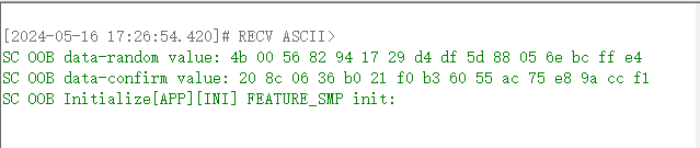
The OOB function at both ends can be turned on or off by sending commands through UART. Once turned on, sc oob pairing can be performed.

Here, set the oob flag of Central to 1 and that of Peripheral to 0. Then send the confirm value and value of the peripheral to the central through the UART serial port. Both Central and Peripheral will reply "pairing success".
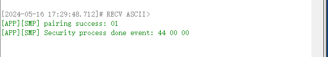
Exception Handling
No Response When Pressing the Button
(1) Hardware reasons: It may be due to the jumper of the key is not connected correctly, please refer to the following figure.

(2) Environment reason: Probably due to the development board not having reset to make the program run after burning.
LED Is Not On
(1) Hardware reasons: may be due to the LED jumper is not connected correctly, please refer to the following figure.

feature_whitelist
- Function: function demonstration of BLE whitelist
- Main hardware: B91 development board x 2
Take Telink B91 chip as example, the application layer code is under tl_ble_sdk/vendor/feature_test/feature_whitelist, it is needed to modify the definition in tl_ble_sdk/vendor/feature_test/feature_config.h:
##define FEATURE_TEST_MODE TEST_WHITELIST
to activate this part of the code and do a demonstration of the whitelist function. Compile and download the bin file to Central and Peripheral. After burning, press the SW4 button of Central to start connection, you can see that the Central and Peripheral are connected successfully. The packet capture is as below.

Modify the MAC address of Central or Peripheral to other addresses via BDT tool.

Reset, click the SW4 button of Central device, you can see that the Central sends Connect Request, but the Peripheral does not respond, which leads to the Central keeps trying to connect.

The Central and Peripheral have established a connection and have added each other's MAC address to their whitelists.
feature_soft_timer
- Function: Demonstration of the Soft Timer function. And as a reference for the demonstration of the IO Debug method.
- Main hardware: B91 development board, logic analyzer or oscilloscope
Take Telink B91 chip as example, the application layer code is under tl_ble_sdk/vendor/feature_test/feature_soft_timer, it is needed to modify the definition in tl_ble_sdk/vendor/feature_test/feature_config.h:
##define FEATURE_TEST_MODE TEST_SOFT_TIMER
to activate this part of the code and enable IO Debug in app_config.h:
##define DEBUG_GPIO_ENABLE 1
to do a functional demonstration of Soft Timer and IO Debug.
Connect PE1 on the development board as PM IO to observe hibernation wake-up. Connect PA3, PB0, PB2, PE0 out as Debug IO 4, 5, 6, 7 for signal display respectively, refer to macro definition DEBUG_GPIO_ENABLE.
After compiling the firmware, burning it into the development board, powering up the logic analyzer to capture the Debug IOs signals, you can see the effect of the 5 IOs captured on the logic analyzer as follows.

The graph shows that the advertising interval is 50ms (or so, with a little dynamic adjustment at the bottom), PA3 toggles every 23ms, PB0 toggles at alternating intervals of 7ms and 17ms, PB2 toggles every 13ms, PE0 toggles every 100ms, refer to the code enabled by the macro definition BLT_SOFTWARE_ENABLE. It can be seen that the device is woken up early when the Soft Timer event is triggered, which means that the events set by Soft Timer are not affected by hibernation.
feature_ota
- Function: function demonstration of BLE OTA
- Main hardware: B91 development board x 2
Take Telink B91 chip as example, the application layer code is under tl_ble_sdk/vendor/feature_test/feature_ota, it is needed to modify the definition in tl_ble_sdk/vendor/feature_test/feature_config.h:
##define FEATURE_TEST_MODE TEST_OTA
to activate this part of the code and do the OTA demo.
In app_config.h, enable BLE_OTA_CLIENT_ENABLE and choose between two transmission protocols: extended protocol and legacy protocol. The extended protocol is a protocol with a faster transmission rate.
##define BLE_OTA_CLIENT_ENABLE      1
##if (BLE_OTA_CLIENT_ENABLE)
        //0: OTA extended protocol; 1: OTA legacy protocol
    #define OTA_LEGACY_PROTOCOL     1
##endif
Compile and get the firmware of Central, and burn it to one of the development boards as Central. Burn the new firmware of Peripheral (white light is always on when powered on) to the OTA file address of Central (there are two addresses in the demo, 0x80000 and 0xC0000). Burn the old firmware to the development board corresponding to Peripheral, and the green light is always on when powered on.
Press the SW5 button on the Central to establish a connection. After the connection is established, press SW2 or SW4 (SW2 corresponds to 0x80000, SW corresponds to 0xC0000) to start the OTA process. The Peripheral receives the new firmware. After the transmission is completed, the Peripheral automatically restarts and runs the new firmware. You can observe that the LED changes from a solid green light to a solid white light.
The packet capture shows that the Central keeps sending WriteCmd to the Peripheral.

When the upgrade is complete, the Peripheral sends a Notify command to the Central, which means that the upgrade was successful, and then sends a Terminate command to disconnect. Since the two are connected by SMP, the Central has the Peripheral's information and reconnects immediately.

feature_l2cap_coc
- Function: BLE COC(Connection Oriented Channel) connection and function demonstration of data transmission
- Main hardware: B91 development board x 2
(1) Change the FEATURE_TEST_MODE macro in feature_config.h to TEST_L2CAP_COC:
##define FEATURE_TEST_MODE TEST_L2CAP_COC
(2) Compile, download and operation:
Compile and burn the generated firmware to the two development boards respectively, power on, press the SW5 (as Central) button of one of the development boards to trigger the connection. If the connection is successful, the red light on the Central end is always on, and the green light on the Peripheral end is always on. Then press SW2 of any development board to trigger the COC connection. After the connection is successful, the blue lights of the two development boards are always on. Then press SW2 of any development board to send data to the other party. The other party will toggle the white light once after receiving the data. You can also view the log through the serial port. The default baud rate of GPIO_PD4 is 1000000.
(3) Capture packets
The following is a screenshot of the COC connection and data transmission, sending 300 bytes of data.
COC connection request:

COC connection respond:
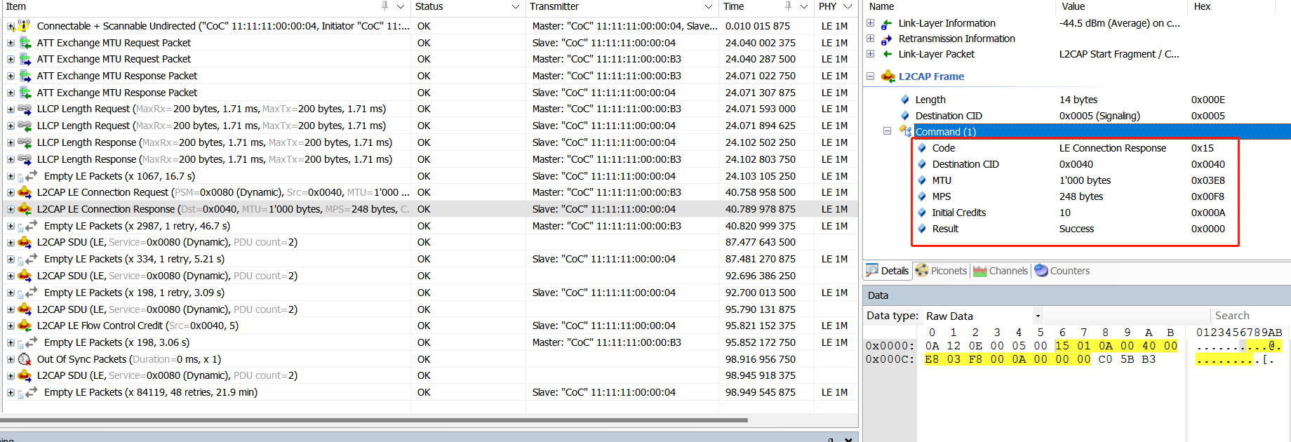
COC data sending 1 (SDU=300, MPS=248, L2CAP layer is divided into 2 frames, the first frame contains 2 bytes of SDU length in the payload header):

COC data transmission 2 (SDU=300, MPS=248, L2CAP layer divided into 2 frames):

feature_ext_adv
- Function: extend advertising
- Main hardware: B92 development board ×1
The application layer code is under B92_ble_multi_conn_sdk/vendor/feature_test/feature_ext_adv, it is needed to modify the definition in B92_ble_multi_conn_sdk/vendor/feature_test/feature_config.h:
##define FEATURE_TEST_MODE TEST_EXT_ADV
The demo enables TLKAPI_DEBUG_CHANNEL_GSUART and uses GPIO_PD4 by default for simulated DEBUG output. View the print information by connecting to the serial port tool RX.
##define TLKAPI_DEBUG_CHANNEL TLKAPI_DEBUG_CHANNEL_GSUART
In ext_adv_set.c, the function app_ext_adv_set_test() implements various extend advertising. The extended advertising content sent can be switched cyclically by pressing the SW5 button.

feature_ext_scan
- Function: extend scanning
- Main hardware: B92 development board×2
The application layer code is under B92_ble_multi_conn_sdk/vendor/feature_test/feature_ext_scan, it is needed to modify the definition in B92_ble_multi_conn_sdk/vendor/feature_test/feature_config.h:
##define FEATURE_TEST_MODE TEST_EXT_SCAN
The demo enables TLKAPI_DEBUG_CHANNEL_GSUART and uses GPIO_PD4 by default for simulated DEBUG output. View the print information by connecting to the serial port tool RX.
##define TLKAPI_DEBUG_CHANNEL TLKAPI_DEBUG_CHANNEL_GSUART
In app_config.h, configure the target phy type to scan:
##define APP_EXT_SCAN_1M                               0x01
##define APP_EXT_SCAN_CODED                         0x02
##define APP_EXT_SCAN_1M_CODED                      0x04
##define EXT_SCAN_TEST_MODE            APP_EXT_SCAN_CODED
One of the two development boards is burned with ext_adv firmware as peripheral, and the other is burned with ext_scan firmware as central. Press the SW5 button of the central to connect to the peripheral that is sending extended broadcasts.

feature_per_adv
- Function: periodic advertising scanning
- Main hardware: B92 development board×1
The application layer code is under B92_ble_multi_conn_sdk/vendor/feature_test/feature_per_adv, it is needed to modify the definition in B92_ble_multi_conn_sdk/vendor/feature_test/feature_config.h:
##define FEATURE_TEST_MODE TEST_PER_ADV
The demo opens TLKAPI_DEBUG_CHANNEL_GSUART and uses GPIO_PD4 by default for simulated DEBUG output. View the print information by connecting to the serial port tool RX.
##define TLKAPI_DEBUG_CHANNEL TLKAPI_DEBUG_CHANNEL_GSUART
Compile the firmware and burn it to the development board. Power it on and run it. You can see the periodic broadcast.

feature_per_adv_sync
- Function: periodic advertising synchronization
- Main hardware: B92 development board×2
The application layer code is under B92_ble_multi_conn_sdk/vendor/feature_test/feature_per_adv_sync, it is needed to modify the definition in B92_ble_multi_conn_sdk/vendor/feature_test/feature_config.h:
##define FEATURE_TEST_MODE TEST_PER_ADV_SYNC
The demo enables TLKAPI_DEBUG_CHANNEL_GSUART and uses GPIO_PD4 by default for simulated DEBUG output. View the print information by connecting to the serial port tool RX.
##define TLKAPI_DEBUG_CHANNEL TLKAPI_DEBUG_CHANNEL_GSUART
In app.c, app_controller_event_callback can determine the HCI event and enter different event callbacks. After scanning the periodic broadcast, synchronization can be established and events can be observed by printing.

Other Modules
Capacitors for 24MHz Crystal
Refer to the position of the 24MHz crystal matching capacitor C1/C4 in the figure below.
The SDK uses the internal capacitor (i.e. the cap corresponding to ana_8a<5:0>) as the matching capacitor for the 24MHz crystal by default. In this case, C1/C4 do not need to be soldered. The advantage of using this solution is that the capacitor can be measured and adjusted on the Telink fixture to achieve the best frequency value for the final application product.

If using external soldered capacitors as matching capacitors for the 24MHz crystal oscillator (C1/C4 capacitors), just call the following API at the beginning of the main function (must be after the sys_init function and before blc_app_loadCustomizedParameters()):
static inline void blc_app_setExternalCrystalCapEnable(u8  en)
{
    blt_miscParam.ext_cap_en = en;
    analog_write(0x8a, analog_read(0x8a) | 0x80);//disable internal cap
}
32KHz Clock Source Selection
By default, the SDK uses the MCU's internal 32kHz RC oscillation circuit, referred to as 32kHz RC.
The user only needs to call the following API at the beginning of the main function (must be before the sys_init function):
void blc_pm_select_internal_32k_crystal(void);
The above API is 32k RC API. The SDK calls blc_pm_select_internal_32k_crystal to select 32k RC by default.
PA
If using RF PA, please refer to drivers/B91/ext_driver/software_pa.h for B91 series chip, and similar for other chips.
First enable the macro below, by default it is disabled.
##ifndef PA_ENABLE
##define PA_ENABLE                    0
##endif
During system initialization, call PA initialization.
void rf_pa_init(void);
Referring to the code implementation, in this initialization, PA_TXEN_PIN and PA_RXEN_PIN are set to GPIO output mode and the initial state is output 0. The GPIOs corresponding to the PA of TX and RX need to be defined by the user:
##ifndef PA_TXEN_PIN
##define PA_TXEN_PIN                  GPIO_PB2
##endif

##ifndef PA_RXEN_PIN
##define PA_RXEN_PIN                  GPIO_PB3
##endif
Register void (*rf_pa_callback_t)(int type) as a callback handler function for PA, which actually handles the following 3 PA states: PA off, TX PA on, RX PA on.
##define PA_TYPE_OFF                  0
##define PA_TYPE_TX_ON                1
##define PA_TYPE_RX_ON                2
User only needs to call rf_pa_init above, app_rf_pa_handler is registered to the bottom layer callback, and BLE will automatically call app_rf_pa_handler's processing when it is in various states.
PhyTest
PhyTest is PHY test, which refers to the test of BLE controller RF performance.
For details, please refer to "Core_v5.4" (Vol 4/Part E/7.8.28~7.8.30) and "Core_v5.4" (Vol 6/Part F "Direct Test Mode").
PhyTest API
The source code of PhyTest is encapsulated in the library file, which provides relevant APIs for users to use. Please refer to the stack/ble/controller/phy/phy_test.h file.
void      blc_phy_initPhyTest_module(void);

ble_sts_t blc_phy_setPhyTestEnable (u8 en);
bool      blc_phy_isPhyTestEnable(void);

int       blc_phytest_cmd_handler (u8 *p, int n);
First, call blc_phy_initPhyTest_module to initialize the PhyTest module. After the application layer triggers PhyTest, the bottom layer automatically calls blc_phy_setPhyTestEnable(1) to turn on the PhyTest mode.
The PhyTest is a special mode that is mutually exclusive with the normal BLE function. Once in PhyTest mode, broadcasting and connection are unavailable. Therefore, PhyTest cannot be triggered when running normal BLE functions.
After PhyTest ends, either power on directly or call blc_phy_setPhyTestEnable(0), at which time the MCU will automatically reboot. Use blc_phy_isPhyTestEnable to determine whether the current PhyTest is triggered.
PhyTest Demonstration
In app_config.h of the tl_ble_sdk demonstration "feature_test", the test mode is changed to "TEST_BLE_PHY" as shown below:
##define FEATURE_TEST_MODE TEST_BLE_PHY
According to the difference in physical interface and test command format, PhyTest can be divided into two test modes, as shown below.
##define        PHYTEST_MODE_THROUGH_2_WIRE_UART        1   //Direct Test Mode through a 2-wire UART interface
##define        PHYTEST_MODE_OVER_HCI_WITH_UART         2   //Direct Test Mode over HCI(UART hardware interface)
Select the test mode of PhyTest, which is defined as uart two-wire mode as follows:
##define BLE_PHYTEST_MODE PHYTEST_MODE_THROUGH_2_WIRE_UART
The following is defined as HCI mode UART interface (hardware interface is UART) phytest:
##define BLE_PHYTEST_MODE PHYTEST_MODE_OVER_HCI_WITH_UART
Users need to set the send and receive callback functions:
blc_register_hci_handler (app_phyTest_rxUartCb, app_phyTest_txUartCb);
The app_phyTest_rxUartCb implements the parsing and execution of cmd sent by the host computer, and app_phyTest_txUartCb implements the feedback of corresponding results and data to the host computer.
Compile the bin file generated by feature_test and test it directly. The user can study the implementation of the code and Central the use of related interfaces.
Note
- When verifying the PHY test function, ensure that no other modules use the RF function.
Debug Method
This chapter introduces several debugging methods commonly used in the development process.
GPIO Simulates UART Printing
To facilitate the debugging for users, the tl_ble_sdk provides an implementation of GPIO simulating UART serial port to output debugging information. This method is only for reference, not an officially recommended method for outputting debugging information. After defining the macro UART_PRINT_DEBUG_ENABLE in app_config.h in the routine as 1, directly use the printf interface consistent with the C language syntax rules in the code for serial output. The default configuration of the GPIO for simulating UART is available in each application routine and can be changed by the user as required.

In general, only modify the baud rate and other IO names in the definition of each line (all PD7 in the picture).
Note
- The baud rate currently supports up to 1 Mbps.
- Since the printing of the GPIO simulating UART serial port will be interrupted by the interrupts, the timing of the simulated UART will be inaccurate, so in the actual use process, there will be occasional garbled printing.
- Since the printing of the GPIO simulating UART serial port will occupy the CPU, it is not recommended to add printing to the interrupts, which will affect the interrupt tasks with high timing requirements.
BDT Tool Reads the Global Variables Value
The official BDT tool provided by Telink can be used not only for burning firmware, but also for some online debug, where the values of global variables in the code can be read under the Tdebug tab. Users can add global variables in the code according to their needs and read them in Tdebug. For details, please refer to the Debug chapter of the BDT User Guide.

Note
- When the chip is in sleep state, the read value is all 0.
- This function depends on the generated list file (the default file name generated by B91 chip is objdump.txt, and xxx.lst by other chips), so the user should also provide the list file as much as possible when providing debug firmware to the official, so that Telink engineers can read the values of some underlying variables through the list file.
BDT Memory Access Function
The official BDT tool provided by Telink can also read the contents of specified locations in Flash, memory and other spaces, and write data through the Memory Access function. It is necessary to make sure that the SWS is on before reading. For details, please refer to the Debug chapter of the BDT User Guide.

BDT Reads PC Pointer
The official BDT tool provided by Telink can be used to read the PC (Program Counter) pointer (not supported by B91 chip), which is very helpful when analyzing the dead problem. For details, please refer to the Debug chapter of the BDT User Guide.

Debug IO
In the app_config.h of each routine has an IO-related definition enclosed in the macro DEBUG_GPIO_ENABLE.

This function is not enabled by default, it is a unified Debug IO definition for Telink engineers to use internally to grab the waveform of IO for debugging by logic analyzer or oscilloscope. However, users can add their own Debug IO at the application layer in a similar way, refer to common/default_config.h.
Note
- In the official release SDK, the Debug IO debugging information in the Stack is included in the library file in a disabled state. So even if the user defines DEBUG_GPIO_ENABLE as 1 at the application layer, it will not enable the Debug IO debugging information in the Stack.
- If Debug IO is enabled, although the Debug IO in the Stack will not work, the Debug IO in the application layer will work, such as rf_irq_handler represented by CHN14 and stimer_irq_handler represented by CHN15 in the tl_ble_sdk.
USB my_dump_str_data
There are several calls of my_dump_str_data API in the tl_ble_sdk. This function is an implementation of B91 to output debug information through the USB interface. It is not an officially recommended method for outputting debugging information, and is only for reference. The purpose of this function is to solve the problem of not being able to output through GPIO simulating UART in interrupt. This function is not enabled by default, define DUMP_STR_EN as 1 to enable it.
JTAG Usage
In order to use the JTAG module, ensure that the following conditions are met before use:
- The four GPIOs of JTAG need to be set to enable mode.
- If the chip is in low-power mode, the chip must exit low-power mode before using JTAG.
- If the JTAG mode cannot be used normally because there is a program in the Flash, use the Telink BDT tool to erase the Flash before use.

Diagnostic Report
(1) In Target Manager, select Diagnostic report.

(2) Select V5 core. do not check SDP (2wires) as current JTAG does not support 2-wire mode, input 0 for address.

(3) Click OK, it generates a Diagnostic report.

Target Configuration
(1) Right click the project folder and select "Target Configuration".

(2) Ensure "SDP (2wires)" is not checked.

Flash Programming
Right click the project folder and select "Flash Burner".

(1) Select SPI_burn.exe in the IDE installation directory.
(2) Select the bin file to be downloaded.
(3) Check "Target management".
(4) Do not check "Target Burn".
(5) Check "Verification". If you need to erase the Flash before burning, check "erase all".

(6) Click "Burn" to download the bin file. If "Verify success" appears, it means the burning is successful.

Appendix
Appendix 1: crc16 Algorithm
unsigned shortcrc16 (unsigned char *pD, int len)
{
   static unsigned short poly[2]={0, 0xa001};
   unsigned short crc = 0xffff;
   unsigned char ds;
   int i,j;

   for(j=len; j>0; j--)
   {
    unsigned char ds = *pD++;
    for(i=0; i<8; i++)
     {
        crc = (crc >> 1) ^ poly[(crc ^ ds ) & 1];
        ds = ds >> 1;
     }
   }

  return crc;
}
Appendix 2: Check Whether Stack Overflows
Principle
In cstartup_, all the contents of the stack are written to 0x55. When the program is running, the used stack data will be rewritten to other values. By checking the size of the stack being rewritten, you can determine the usage of the stack and whether the stack overflows.
Method
(1) Open boot/cstartup_, enable the content in _FILL_STK.
_FILL_STK:
##if 1
    lui    t0, 0x55555
    addi   t0, t0, 0x555
    la     t2, _BSS_VMA_END
    la     t3, _STACK_TOP
_FILL_STK_BEGIN:
    bleu   t3, t2, _MAIN_FUNC
    sw     t0, 0(t2)
    addi   t2, t2, 4
    j      _FILL_STK_BEGIN
##endif
(2) Determine the bottom address of the stack according to the SRAM space allocation in Section 2.1.2.1 of this manual.
(3) After downloading the .bin file of the program using the BDT software, click Reset to run the program. Then connect and pair the peripheral with the central.
(4) After pairing, use "Tool -> Memory Access" in BDT to read the data in the RAM. The example diagram is as follows.

(5) Press the "Tab" key on the keyboard to generate a Read.bin file to save the data. The file address is: BDT installation path -> config -> user, Read.bin.
(6) Use hexadecimal viewing software to open Read.bin. If there is no continuous 0x55, it means that the stack overflows to the .bss segment. Or, a more accurate method is to find the allocated stack top address in the .lst file generated by the project, as shown in the figure below. Then check in Read.bin whether this address has been rewritten to other content. If it has been rewritten, it means that the stack has overflowed.
