Telink LE Audio CIS SDK Developer Handbook
Quick Start Guide
Overview
LE Audio is the next generation of Bluetooth audio technology that makes it possible to transmit audio over low-power Bluetooth. It supports new use cases and significantly reduces power consumption compared to classic (BR/EDR) audio. Bluetooth LE Audio is designed to reduce power consumption, minimize latency, narrow transmission bandwidth, and ultimately improve performance. LE Audio and Classic Audio standards will continue to coexist with features supported by both. LE Audio will have a broader feature set, lower power consumption and better perceived audio quality. LE Audio not only offers better audio quality and longer playback times, but also introduces new features and opportunities.
CIS (Connected Isochronous Stream) is one of the use cases in LE Audio, the other use case is BIS (Broadcast Isochronous Stream), which will be described in another handbook, and here only for CIS.
SDK Features
-
Supports Bluetooth LE 5.3;
-
Supports LE Audio transmission, 48KHz/16-bit downstream (LC3), 16KHz/16-bit upstream (LC3), audio latency ≤ 40 ms;
-
Supports multiple sample rates: 8kHz, 16kHz, 24kHz, 32kHz, 44.1kHz, 48kHz;
-
Supports TWS headphones;
-
Supports LC3 CODEC;
-
Supports Adaptive Frequency Hopping;
-
Supports headset.
SDK Application Areas
-
TWS headphones
-
Headset
Download Tools
Tools: Burning and Debugging Tools
Firmware bin: http://192.168.48.36/sdk_app/ble/telink_b91m_ble_audio_sdk (Telink internal URL).
Demonstration
Please refer to Telink BLE Audio SDK User Guide (Telink internal URL).
SDK Usage and Architecture
Software Preparation
Development Software Installation and Usage
Log in to the Telink document center, select Tools in the Software website to see the download options and how to activate and import the project. Here is an introduction to import and use this SDK.
(1) Open the IDE; right-click in Project Explorer, and then click Import in the pop-up menu, as shown below:

(2) Select "Existing Projects into Workspace" and click Next, as shown below:

(3) Click Browse..., select the SDK directory, the BLE_AUDIO_SDK will pop up in the Projects window, ensure the corresponding chip is selected (B91 corresponds to the TLSR951x chips), and then click Finish to complete the SDK import, as shown in the figure:

Build Order
Audio_unicast_client refers to the Client project, audio_unicast_server refers to the Server project. Currently, building the Client requires compiling ble_audio_bootloader first, followed by the Client project. The Server does not currently include a bootloader, so the Server project can be built directly. As shown in the following figure:

If the build is successful, you will see the bin file highlighted below in B91m_ble_sdk\build\B91\ audio_unicast_client\output folder. The same applies to the Server. However, since the Client includes a bootloader, you must use the bin file that starts with "boot", as shown in the figure below:

Software Organization Structure
After importing the project in the IDE, the folder organization is displayed as shown in the figure below. There are 8 top level folders: algorithm, application, boot, common, drivers, proj_lib, stack, vendor.

-
algorithm: Provides some general purpose algorithms, such as aes_ccm, LC3 CODEC. Most of the C files for the algorithms are packaged in library files, with only the corresponding header files exposed.
-
application: Provides some general purpose application handlers, such as print, keyboard, and so on.
-
boot: Provides the software bootloader of the chip, i.e. the assembly process after MCU power-on startup or deepsleep wakeup, to build up a good environment for the running of the C language program later.
-
common: Provides some general cross-platform functions, such as memory handlers, string handlers, and so on.
-
drivers: Provides hardware settings and peripheral drivers that are closely related to the MCU, such as clock, flash, I2C, USB, GPIO, UART and so on.
-
proj_lib: The libraries necessary for SDK operation (such as libB91_driver_i2.a) are stored. Files such as the BLE protocol stack, RF driver, PM driver, etc. are packaged in the library files, and the source files are not visible to the user.
-
stack: Stores files related to the BLE protocol stack.
-
vendor: Used to store user application layer code.
Client/Server Task Architecture
In SDK, RF and system interrupts are used by the BLE stack and are not open to users, so users do not need to care about the specifics. The following interrupts are all used in the current SDK, other interrupts are not used, users can use them as needed.
Time0 Interrupt
The Time0 interrupt is mainly used to control the play time of audio data.
USB Interrupt
The USB interrupt contains the input and output of USB data, including Speak, MIC, UDB and HID. HID is used as a control test.
UART Interrupt
The UART interrupts include UART0 and UART1. Currently UART0/1 can be used to print the system log and can also be used as a shell component, which is also used as a test for the production test.
app_le_enhanced_connection_complete_event_handle
Connection completion event, where the user can do some deterministic operations after the connection is completed, such as: identifying the MAC address of the Client side of the connection, the change of LED or tone of the Server side after the connection is completed.
app_disconnect_event_handle
Disconnect ACL event, user can add logic after disconnecting ACL in here, such as light effect, and determine for what reason the acl connection was disconnected, deciding whether to restart Scanning/Advertising.
app_controller_event_callback
Event callbacks for BLE stack Controller.
app_host_event_callback
Event callbacks for the Host layer of the BLE stack.

Connection and Disconnection
In the LE Audio SDK-Unicast scenario, the connection mainly consists of ACL (asynchronous) and CIS (synchronous) connections. The ACL connection serves as the foundation for the CIS connection, meaning a CIS connection can only be established after an ACL connection has been set up. When disconnecting, the ACL connection remains unaffected if the CIS is disconnected. However, if the ACL connection is disconnected while a CIS connection exists, the CIS connection will also be disconnected. To address service discovery issues in multi-device scenarios (such as a TWS scenario where one Central connects to two Peripherals), LE Audio introduces the CSIP (Coordinated Set Identification Profile). With CSIP, once the Central discovers one Peripheral in the coordinated set, it can then discover all other Peripherals within that set. In addition, establishing a CIS connection involves configuring audio parameters on both the Client and Server, as well as managing changes in the data stream state.
Connection
Connection Initiation
Client
Set MAC address:
void blc_initMacAddress(int flash_addr, u8 *mac_public, u8 *mac_random_static);
Set the communication interval for Client ACL connection:
blc_ll_setAclCentralBaseConnectionInterval(CONN_INTERVAL_20MS);
Set the Tx power:
blc_ll_setDefaultTxPowerLevel(RF_POWER_P9dBm);
Set the encryption level:
blc_smp_setSecurityLevel_central(Unauthenticated_Pairing_with_Encryption);
blc_smp_setSecurityParameters_central(Bondable_Mode, 0, LE_Secure_Connection, 0, 0, IO_CAPABILITY_NO_INPUT_NO_OUTPUT);
blc_smp_setEcdhDebugMode_central(debug_mode);
Select a scenario, currently available scenarios are TWS and Headset. Take TWS as an example in this document.
#define APP_AUDIO_SCENE APP_SCENE_TWS
Configure the upstream and downstream buffer, sample and byte sizes.
#define APP_AUDIO_INPUT_BUFFER_SIZE                  2048
#define APP_AUDIO_INPUT_FRAME_SAMPLE_MAX             480
#define APP_AUDIO_INPUT_FRAME_ENCODE_BYTES_MAX       155
#define APP_AUDIO_OUTPUT_BUFFER_SIZE                 2048
#define APP_AUDIO_OUTPUT_FRAME_SAMPLE_MAX            160
#define APP_AUDIO_OUTPUT_FRAME_ENCODE_BYTES_MAX      40
Select the upstream and downstream scenes and the sampling rate.
typedef enum{BLC_AUDIO_1_SVR_1_SINK_1_CHN_1_SRC_N_CHN_N_CISES_1_STREAMS_1, BLC_AUDIO_2_SVR_1_SINK_N_CHN_N_SRC_1_CHN_1_CISES_1_STREAMS_1,
.......
BLC_AUDIO_11II_SVR_2_SINK_2_CHN_1_SRC_2_CHN_1_CISES_2_STREAMS_4, BLC_AUDIO_STD_AUDIO_CONFIGURATIONS_E_MAX,} std_unicast_aud_cfg_enum;
The audio capability supports initialization and requires user selection.
//BAP_v1.0.1 page 25, Table 3.5: Unicast Server audio capability support requirements
//BAP_v1.0.1 page 33, Table 3.11: Unicast Client audio capability support requirements
const std_codec_settings_t codecSettings[16] = {
{
BLC_AUDIO_SUPP_FREQ_FLAG_8000, BLC_AUDIO_FREQ_CFG_8000, BLC_AUDIO_SUPP_DURATION_FLAG_7_5,BLC_AUDIO_DURATION_CFG_7_5, 26
},
......
{
BLC_AUDIO_SUPP_FREQ_FLAG_48000,BLC_AUDIO_FREQ_CFG_48000, BLC_AUDIO_SUPP_DURATION_FLAG_10, BLC_AUDIO_DURATION_CFG_10,  155
},
};
Set the parameters of the extended broadcast.
ble_sts_t blc_ll_setExtScanParam (own_addr_type_t ownAddrType, scan_fp_type_t scan_fp,scan_phy_t scan_phys,scan_type_t scanType_0, scan_inter_t scanInter_0, scan_wind_t scanWindow_0,scan_type_t scanType_1, scan_inter_t scanInter_1, scan_wind_t scanWindow_1);
Enable broadcast.
ble_sts_t blc_ll_setExtScanEnable (scan_en_t extScan_en, dupe_fltr_en_t filter_duplicate, scan_durn_t duration, scan_period_t period);
Server
Set the MAC address.
void blc_initMacAddress(int flash_addr, u8 *mac_public, u8 *mac_random_static)
Set the Tx power.
blc_ll_setDefaultTxPowerLevel(RF_POWER_P9dBm);
Set the encryption level.
blc_smp_setSecurityLevel_central(Unauthenticated_Pairing_with_Encryption);
blc_smp_setSecurityParameters_central(Bondable_Mode, 0, LE_Secure_Connection, 0, 0, IO_CAPABILITY_NO_INPUT_NO_OUTPUT);
blc_smp_setEcdhDebugMode_central(debug_mode);
BAP unicast Server initialization.
blc_audio_registerBapUnicastServer(&unicastSvrParam);
Parameter description.
typedef struct{
u8 sinkPacNum;                  //number of Sink PAC records
const blc_audio_pacParam_t* sinkPac;    //Sink PAC
u32 sinkAudioLocations;         //Sink Audio Location, BLC_AUDIO_LOCATION_FLAG_FL
u8 sourcePacNum;                    //number of Source PAC records
const blc_audio_pacParam_t* sourcePac;  //Source PAC
u32 sourceAudioLocations;       //Source Audio Location, BLC_AUDIO_LOCATION_FLAG_FL
u16 availableSinkContexts;      //Available Sink Contexts, BLC_AUDIO_CONTEXT_TYPE_UNSPECIFIED
u16 availableSourceContexts;    //Available Source Contexts, BLC_AUDIO_CONTEXT_TYPE_UNSPECIFIED
u16 supportedSinkContexts;      //Supported Sink Contexts, BLC_AUDIO_CONTEXT_TYPE_UNSPECIFIED
u16 supportedSourceContexts;    //Supported Sink Contexts, BLC_AUDIO_CONTEXT_TYPE_UNSPECIFIED
} blc_pacss_regParam_t;
-
sinkPacNum: The number of the Sink PACs.
-
sinkPac: The capabilities of the Sink PAC, representing the audio receiving capability. This attribute only needs to be defined when the device supports audio reception.
-
sinkAudioLocations: The audio locations supported by the Sink.
-
sourcePacNum: The number of Source PACs, representing the audio sending capability. This attribute only needs to be defined when the device supports audio transmission.
-
sourcePac: The capabilities of the Source PAC.
-
sourceAudioLocations: The audio locations supported by the Source.
-
availableSinkContexts: Available Sink audio content.
-
availableSourceContexts: Available source audio content.
-
supportedSinkContexts: Supported Sink audio content.
-
supportedSourceContexts: Supported source audio content.
The default configuration can be modified by the user. However, the default configuration is currently not used; instead, the constant blc_pacss_regParam_t pacsParam is used.
const blc_pacss_regParam_t defaultPacsParam = {
.sinkPacNum = 1,
    .sinkPac = defaultPac,
    .sinkAudioLocations = BLC_AUDIO_LOCATION_FLAG_FL,
    .sourcePacNum = 1,
    .sourcePac = defaultPac,
    .sourceAudioLocations = BLC_AUDIO_LOCATION_FLAG_FL,
    .availableSinkContexts = BLC_AUDIO_CONTEXT_TYPE_UNSPECIFIED|BLC_AUDIO_CONTEXT_TYPE_CONVERSATIONAL|BLC_AUDIO_CONTEXT_TYPE_MEDIA,
.availableSourceContexts = BLC_AUDIO_CONTEXT_TYPE_UNSPECIFIED|BLC_AUDIO_CONTEXT_TYPE_CONVERSATIONAL|BLC_AUDIO_CONTEXT_TYPE_MEDIA,
.supportedSinkContexts = BLC_AUDIO_CONTEXT_TYPE_UNSPECIFIED|BLC_AUDIO_CONTEXT_TYPE_CONVERSATIONAL|BLC_AUDIO_CONTEXT_TYPE_MEDIA,
.supportedSourceContexts = BLC_AUDIO_CONTEXT_TYPE_UNSPECIFIED|BLC_AUDIO_CONTEXT_TYPE_CONVERSATIONAL|BLC_AUDIO_CONTEXT_TYPE_MEDIA,
};
Define the position of the Audio, commonly the left and right channels.
enum{
BLC_AUDIO_LOCATION_FLAG_FL                = BIT(0),  // Front Left
BLC_AUDIO_LOCATION_FLAG_FR                = BIT(1),  // Front Right
.......
BLC_AUDIO_LOCATION_FLAG_RS                = BIT(27), // Right Surround
BLC_AUDIO_LOCATION_FLAG_RFU               = BITS(28,29,30,31) // bit28 ~ bit29
};
#define BLC_AUDIO_CHANNEL_ALLOCATION_RFU(param) (param&BLC_AUDIO_LOCATION_FLAG_RFU)
Set the audio capabilities of the Server.
const blc_audio_pacParam_t sinkPac[] = {
{
LC3_CAP_16_2(BLC_AUDIO_CHANNEL_COUNTS_1, 1),
METADATA_CONTEXTS(BLC_AUDIO_CONTEXT_TYPE_CONVERSATIONAL|BLC_AUDIO_CONTEXT_TYPE_MEDIA),
},
.......
{
LC3_CAP_48_2(BLC_AUDIO_CHANNEL_COUNTS_1, 1),
METADATA_CONTEXTS(BLC_AUDIO_CONTEXT_TYPE_CONVERSATIONAL|BLC_AUDIO_CONTEXT_TYPE_MEDIA),
},
};
Initialize CSIP.
blc_audio_registerCSISControlServer(&csipSetMemberParam);
Set the SIRK value (Set Identity Resolving Key).
#define CSISS_DEFAULT_LOCK_TIMEOUT              60      //60s
#define CSISS_DEFAULT_PLAIN_SIRK                {0x00, 0x01, 0x02, 0x03, 0x04, 0x05, 0x06, 0x07, 0x08, 0x09, 0x0a, 0x0b, 0x0c, 0x0d, 0x0f, 0x10}        //must 16byte
const blc_csiss_regParam_t defaultCsipSetMemberParam =
{
    .setSize = 2,
    .setRank = 1,
    .lockedTimeout = CSISS_DEFAULT_LOCK_TIMEOUT,
    .SIRK_type = 1,
    .SIRK = CSISS_DEFAULT_PLAIN_SIRK,
};
Select a scenario, currently available scenarios are TWS and Headset. Take TWS as an example in this document.
#define APP_AUDIO_SCENE APP_SCENE_TWS
Set the extended broadcast parameter.
blc_ll_setExtAdvParam(ADV_HANDLE0, ADV_EVT_PROP_EXTENDED_CONNECTABLE_UNDIRECTED, ADV_INTERVAL_30MS, ADV_INTERVAL_30MS, BLT_ENABLE_ADV_ALL, OWN_ADDRESS_PUBLIC, BLE_ADDR_PUBLIC, NULL, ADV_FP_NONE, TX_POWER_3dBm,BLE_PHY_1M, 0, BLE_PHY_1M, ADV_SID_0, 0);
Initialize the broadcast type, and the users can also add the custom broadcast type they need in the extended broadcast.
blc_adv_ltv_t *adv_ltvs[] = {
(blc_adv_ltv_t *) &advDefFlags,
    (blc_adv_ltv_t *) &advDefCompleteName,
    (blc_adv_ltv_t *) &advDefAppearance,
    (blc_adv_ltv_t *) &advIncompleteList,
    (blc_adv_ltv_t *) &advCsisRsi,
(blc_adv_ltv_t *) &capTargetAnnouncement,
    (blc_adv_ltv_t *) &bapTargetDefAnnouncement,
(blc_adv_ltv_t *) &advTmapRole,
};
u8 advData[255];
u8 adv_ext_len = blc_adv_buildAdvData(adv_ltvs,ARRAY_SIZE(adv_ltvs),advData);
Enable extended broadcast.
ble_sts_t blc_ll_setExtAdvEnable(adv_en_t enable, u8 adv_handle, u16 duration, u8 max_extAdvEvt);
Connection Process
Client: central_pairing_enable = 1 && within close range && blc_ll_setExtScanEnable(BLC_SCAN_ENABLE, DUP_FILTER_DISABLE, SCAN_DURATION_CONTINUOUS, SCAN_WINDOW_CONTINUOUS);
Server: within close range && blc_ll_setExtAdvEnable(BLC_ADV_ENABLE, ADV_HANDLE0, 0, 0)
(1) As long as the Client and Server are set up as described above, they can establish a connection. During this process, the Client will save the Server's pairing information, including the MAC address.
(2) If the devices are powered off and then on again (or after any disconnection), the Client will first check for the Server's information stored in flash. If found, the Client and Server will go through a reconnection process. In this case, the Client does not need to rediscover services on the Server, making reconnection significantly faster than the initial pairing.
(3) If the user manually clears the stored information, the next connection will follow the full pairing process again.
The connection conditions set on the Client side are as follows:
(1) user_manual_pairing =central_pairing_enable && (temp_rssi > -56);
(2) if(blc_csis_resolveRSI(appCtrl.acl_csis_sirk, adv_data->data))
{
rsi_auto_connect = (1 &&(temp_rssi > -56));
}
(3) if(central_auto_connect || user_manual_pairing || rsi_auto_connect)
Each of the three conditions serves a specific purpose. The first one, central_auto_connect, is not currently used in the SDK, so it will not be introduced for now.
The second condition requires the user to manually enable pairing, and the devices must be within a certain range.
The third condition involves the Client actively searching its stored information for the saved SIRK value to ensure it can correctly reconnect to the Server within the Coordinated Set.
The filtering conditions set on the Client side are as follows:
if(ServiceUUID == SERVICE_UUID_AUDIO_STREAM_CONTROL )
{
    app_adv_announcement_t *p = (app_adv_announcement_t *)&adv_data->data[2];
if( p->available_audio_context > 0x100)
{
    announcement_filter = 1;
}
if(p->announcement_type == BLC_AUDIO_TARGETED_ANNOUNCEMENT && p->available_audio_co ntext | (BLC_AUDIO_CONTEXT_TYPE_CONVERSATIONAL|BLC_AUDIO_CONTEXT_TYPE_MEDIA))
{
    announcement_filter = 1;
}
}
The retrieved information will be evaluated. Currently, only certain Telink devices and a specific type of Server are supported. Adaptation for other Servers can be done based on their specific implementation.
The ACL connection process between the Client and Server is not covered here. Below is a brief introduction to the CIS process. For details, please refer to the Bluetooth Core Specification 5.3, pages 2979 and 2980.

Disconnection
Disconnection Process
In LE Audio, connections are established by first creating an ACL connection, followed by a CIS connection. The CIS audio stream must be established after the ACL connection and depends on it. If only the CIS connection is disconnected, the ACL connection remains unaffected. However, if the ACL connection is disconnected, the CIS connection will also be disconnected.
Disconnection caused by ACL termination:

Actively terminating the isochronous stream (can be initiated by either the Client or the Server):

Disconnection API:
blc_ll_disconnect (u16 connHandle, u8 reason);
blc_ll_cis_disconnect(u16 cisHandle, u8 reason);
Reason for Disconnection
typedef enum {
    BLE_SUCCESS = 0,
//  HCI Status, See the Core_v5.0(Vol 2/Part D/1.3 "list of Error Codes") for more information)
    HCI_ERR_UNKNOWN_HCI_CMD                                        = 0x01,
    HCI_ERR_UNKNOWN_CONN_ID                                        = 0x02,
    HCI_ERR_HW_FAILURE                                             = 0x03,
    HCI_ERR_PAGE_TIMEOUT                                           = 0x04,
    HCI_ERR_AUTH_FAILURE                                           = 0x05,
    HCI_ERR_PIN_KEY_MISSING                                        = 0x06,
......
    //LE Audio Server
    LE_AUDIO_SERVER_INVALID_SERVICE                                = 0xF0,
    LE_AUDIO_SERVER_INVALID_HANDLE,
} ble_sts_t;
If the user is unsure about the meaning of certain disconnection reasons, they can contact Telink technical support for assistance.
Out-of-range disconnection & Power-off disconnection: If the user triggers either of these disconnection scenarios, the reported reason is typically HCI_ERR_CONN_TIMEOUT.
Clearing pairing records: There are multiple ways to clear pairing records; this section introduces only one method.
for(u8 i=0;i<appCtrl.acl_max_num;i++){
    if(0 != conn_dev_list[i].conn_state){
        if(blc_ll_disconnect(conn_dev_list[i].conn_handle, HCI_ERR_REMOTE_USER_TERM_CONN) == BLE_SUCCESS)
        {
            dev_char_info_t* dev_char_info = dev_char_info_search_by_connhandle(conn_dev_list[i].conn_handle);//connHandle has marked on on central_unpair_enable
            #if (ACL_CENTRAL_SMP_ENABLE)
            blc_smp_deleteBondingPeripheralInfo_by_PeerMacAddress(dev_char_info->peer_adrType, dev_char_info->peer_addr);
            #endif
            }
        }
    }
Incident Report
Application Layer Report
Refer to app_audio.c and app_audio.h. In the SDK, certain events from the LE Controller and Host are handled internally by the Audio Profile layer. Whether these intercepted events are reported depends on whether the corresponding event masks are enabled — for the LE Controller (blc_hci_le_setEventMask_cmd) and for the Host (blc_gap_setEventMask).
The event callback at the Profile layer serves as the entry point for all audio stream processing. Users need to use this callback to obtain the state of ASEs and perform the corresponding operations at the application (APP) layer based on those states.
The SDK currently demonstrates reporting of the following events:
static const app_audio_evtCb_t unicastCb[] = {
    /* Event for controller or Host */
    {PRF_EVTID_ACL_CONNECT              , (void*)app_event_acl_connect},
    {PRF_EVTID_ACL_DISCONNECT           , (void*)app_event_acl_disconnect},
    {AUDIO_EVT_CIS_CONNECT              , (void*)app_event_cis_connect},
    {AUDIO_EVT_CIS_DISCONNECT           , (void*)app_event_cis_disconnect},
    {AUDIO_EVT_CIS_REQUEST              , (void*)app_event_cis_request},
    {PRF_EVTID_SMP_SECURITY_DONE        , (void*)app_event_security_done},
    /* Event for Client SDP */
    {PRF_EVTID_CLIENT_SDP_FOUND         , (void*)app_event_audio_sdp_found},
    {PRF_EVTID_CLIENT_SDP_FAIL          , (void*)app_event_audio_sdp_not_found},
    {PRF_EVTID_CLIENT_ALL_SDP_OVER      , (void*)app_event_audio_sdp_over},
    /* Event for BAP Unicast Server */
    {AUDIO_EVT_BAPUS_CODEC_CONFIGURED   , (void*)app_ep_codec_configured},
    {AUDIO_EVT_BAPUS_QOS_CONFIGURED     , (void*)app_ep_qos_configured},
    {AUDIO_EVT_BAPUS_ENABLING           , (void*)app_ep_enabling},
    {AUDIO_EVT_BAPUS_RECEIVE_STREAMING  , (void*)app_ep_receive_streaming},
    {AUDIO_EVT_BAPUS_SEND_STREAMING     , (void*)app_ep_send_streaming},
    {AUDIO_EVT_BAPUS_DISABLING          , (void*)app_ep_disabling},
    {AUDIO_EVT_BAPUS_RELEASING          , (void*)app_ep_releasing},
};
(1) ACL Connect & ACL Disconnect
app_event_acl_connect
app_event_acl_disconnect
Through this event, the user can obtain the current ACL connection status. Based on the status, the user may choose to enable or disable extended advertising within the event callback as needed.
(2) CIS Connect & CIS Disconnect & CIS REQUEST
app_event_cis_connect
app_event_cis_disconnect
app_event_cis_request
This type of event allows the user to obtain the CIS connection status. CIS-related operations are handled by the Profile layer, and this event is intended to help users better understand the audio stream establishment process. No action is required in the event callback.
(3) SDP_FOUND & SDP_FAIL & SDP_OVER
app_event_audio_sdp_found
app_event_audio_sdp_not_found
app_event_audio_sdp_over
After Profile registration, during the first ACL connection, the Unicast Server will perform Service Discovery for the registered Profile on the Unicast Client. If the discovery is successful, the Profile layer will trigger the AUDIO_EVT_CLIENT_SDP_FOUND callback. If the discovery fails, it will trigger the AUDIO_EVT_CLIENT_SDP_FAIL callback. This allows the user to clearly determine whether the registered Profile is present on the Unicast Server side. Each Profile event corresponds to an ID defined in audio_svc_role_enum.
Host Event Report
int app_host_event_callback (u32 h, u8 *para, int n)
{
    u8 event = h & 0xFF;
    switch(event)
    {
        case GAP_EVT_SMP_PAIRING_BEGIN:
        {
        }
        break;
......
}
......
}
The reporting of other Host layer events is handled in the Host event callback, and there are not many events that require user attention.
Controller Event Report
int app_controller_event_callback (u32 h, u8 *p, int n)
{
    if (h &HCI_FLAG_EVENT_BT_STD)       //Controller HCI event
    {
        u8 evtCode = h & 0xff;
        //------------ disconnect -------------------------------------
        if(evtCode == HCI_EVT_DISCONNECTION_COMPLETE)  //connection terminate
        {
            app_disconnect_event_handle(p);
        }
......
}
......
}
The reporting of other Controller layer events is handled in the Controller event callback, mainly including connection complete events, advertising events, connection update events, and CIS connection complete events. These events are already handled by the SDK, please refer to the corresponding sections for more details.
Audio Data Flow
In audio stream configuration, the Unicast Server exposes its audio capabilities to the Unicast Client via PAC. After obtaining the audio capabilities of the Unicast Server, the Unicast Client selects a set of audio parameters based on its own preferences and configures the Unicast Server, then starts the audio stream. During this process, the Unicast Server acts passively, needing to update its CODEC configuration in real time according to the parameters set by the Unicast Client.
The Unicast Server retrieves audio endpoint parameters from the ASE state once it reaches the "CODEC Configured" state. When all endpoint parameters are obtained (which can be considered complete when the QoS Configured state is reported), the Unicast Server configures LC3 and the CODEC locally. Once configuration is completed, audio data begins to flow.
The audio stream will persist unless the audio input path or microphone has no data to collect, or the user actively disconnects the audio link.
Data Stream State Machine
ASCS (Audio Stream Control Service) exposes the device’s audio stream endpoints and allows the Client to discover, configure, establish, and control the audio stream endpoints and the associated unicast audio streams.
The ASCS service is primarily carried by Audio Stream Endpoint (ASE), which are categorized into two types:
-
Source ASE: Direction of outgoing audio streams.
-
Sink ASE: Direction of incoming audio streams.

Source ASE has 7 states, which are:
-
IDLE: Standby state. This is the default initial state. It can also be entered from the Releasing state via the Release operation.
-
CODEC Configured: Audio parameters such as sample rate, bit width, length have been configured. This state can be entered from the IDLE state via the Config CODEC operation, from the Releasing state by the Release operation, or from the QoS Configured state by the Config CODEC operation.
-
QoS Configured: Connection parameters such as PHY, Retransmit Num, Max Transport Latency have been configured. This state can be entered from CODEC Configured state via Config QoS operation, or from Disabling state via Receive Stop Ready operation.
-
Enabling: Enable state, during which the CIS between Client and Server is being established or has already been established. This state can only be entered from the QoS Configured state via the Enable operation. Metadata can be updated in this state.
-
Streaming: The audio stream has been successfully established, and audio data can now be transmitted between Client and Server. This state can only be entered from the Enabling state via the Receive Start Ready operation. Metadata can be updated in this state.
-
Disabling: Disabling state, indicating the audio stream is stopping. This is a transitional state and can revert to the QoS Configured state via the Receive Start Stop operation. Note: This state exists only for Source ASEs. It can be entered from either the Enabling or Streaming state via the Disable operation.
-
Releasing: Releasing state, indicating that audio resources are being released. This is a transitional state that can be entered from any state except IDLE. It can transition to either the CODEC Configured state (as a cached state to reduce setup time when re-establishing an audio stream) or to the IDLE state (for full release), via the Released operation.
Sink ASE has 6 states, and all its states and operations are the same as those of the Source ASE, except for the absence of the Disabling state. Therefore, when disabling from either the Enabling or Streaming state, the Sink ASE will return directly to the QoS Configured state.
Downlink Data Stream
Data Flow Diagram
The data flow is shown in the diagram below and is divided into Application and BLE Stack layers. The sending and receiving processes within the BLE Stack are fully handled by the SDK and do not require user intervention. Users only need to focus on the Application layer, for which the SDK provides complete interfaces. With simple configuration, users can easily utilize the functionality.


Audio Data Collection
Downstream USB data collection:
_attribute_ram_code_ void  app_usb_irq_proc (void)
{
    if (usbhw_get_eps_irq()&FLD_USB_EDP6_IRQ)
    {
......
        for (unsigned int i=0; i<len; i++)
        {
            usbData[i] = reg_usb_ep6_dat;
        }
        tlk_buffer_write(usbData,len,TLK_BUFFER_1);
......
    }
}
During initialization, the data interval, size, and endpoints are already defined, so the data can be retrieved directly from the endpoint within the function. Currently, the SDK places the received data into a dedicated buffer.
Audio Algorithm Processing
void tlka_ppm_asrc_16_bit_init(void *st, TLKA_PPM_ASRC_CHANNEL channel, int ppm);
void tlka_ppm_asrc_24_bit_init(void *st, TLKA_PPM_ASRC_CHANNEL channel, unsigned int buffer_len, int ppm_data_len_max);
Currently, the SDK does not include ASRC or any other audio algorithms. For more information, please refer to the algorithms section.
LC3 CODEC
A single LC3 encoder/decoder supports only one audio channel. Therefore, stereo audio requires two LC3 CODECs to function properly. In the SDK, the API source file for the LC3 CODEC is located at: algorithm/audio_alg/lc3/lc3.h.
To use the LC3 CODEC, users must redefine macros to specify the number of LC3 encoder and decoder channels. For example, in the CIS Client Demo, stereo audio is captured and encoded to be sent to two Servers, and data from both Servers is decoded into stereo audio. Thus, the number of LC3 encoders should be set to 2, and the number of LC3 decoders should also be set to 2.
#define LC3_ENCODE_CHANNEL_COUNT 2
#define LC3_DECODE_CHANNEL_COUNT 2
For other scenarios, users should configure the number of CODECs based on specific requirements.
Note
- Pay attention to the RAM size (please refer to the appendix).
lc3enc_encode_init
This API is used to initialize the LC3 encoder and is intended for users with knowledge of the LC3 encoder.
int lc3enc_encode_init(u8 index, u32 nSamplerate, u32 nBitrate, u16 nMs_mode);
Input parameters:
-
index: LC3 encoder index, the range is [0,LC3_ENCODE_CHANNAL_COUNT-1].
-
nSamplerate: Audio sampling rate in Hz. 8 kHz corresponds to 8000 Hz.
-
nBitrate: Bitrate after encoding.
-
nMs_mode: Audio frame duration. 1 indicates 7.5 ms, 0 indicates 10 ms.
-
Return Value: 0 indicates successful initialization; any other value indicates failure.
lc3enc_encode_init_bap
This API is used to initialize the LC3 encoder using parameters defined by the BAP specification.
int lc3enc_encode_init_bap(u8 index, u8 samplingFreq, u8 frameDuration, u16 perCodecFrame);
Input parameters:
-
index: LC3 encoder index, the range is [0,LC3_ENCODE_CHANNAL_COUNT-1].
-
samplingFreq: Audio sampling rate.
-
frameDuration: Audio sampling period.
-
perCodecFrame: the length after encoding.
-
Return Value: 0 indicates successful initialization; any other value indicates failure.
lc3enc_encode_pkt
This API performs the actual audio data encoding and requires initializing the encoder module first.
int lc3enc_encode_pkt(u8 index, u8* rawData, u8* encData);
Input parameters:
-
index: LC3 encoder index, the range is [0,LC3_ENCODE_CHANNAL_COUNT-1].
-
rawData: Pointer to the raw data.
-
encData: Pointer to the encoded data.
-
Return Value: 0 indicates successful initialization; any other value indicates failure.
lc3dec_decode_init
This API is used to initialize the LC3 decoder and is intended for users with knowledge of the LC3 decoder.
int lc3dec_decode_init(u8 index, u32 nSamplerate, u32 nBitrate, u16 nMs_mode);
Input parameters:
-
index: LC3 decoder index, the range is [0,LC3_DECODE_CHANNAL_COUNT-1].
-
nSamplerate Audio sampling rate in Hz: 8 kHz corresponds to 8000 Hz.
-
nBitrate: Bitrate after encoding.
-
nMs_mode: Audio frame duration. 1 indicates 7.5 ms, 0 indicates 10 ms.
-
Return Value: 0 indicates successful initialization; any other value indicates failure.
lc3dec_decode_init_bap
This API is used to initialize the LC3 decoder using parameters defined by the BAP specification.
int lc3dec_decode_init_bap(u8 index, u8 samplingFreq, u8 frameDuration, u16 perCodecFrame);
Input parameters:
-
index: LC3 decoder index, the range is [0,LC3_DECODE_CHANNAL_COUNT-1].
-
samplingFreq: Audio sampling rate.
-
frameDuration: Audio sampling period.
-
perCodecFrame: the length after encoding.
-
Return Value: 0 indicates successful initialization; any other value indicates failure.
lc3dec_decode_pkt
This API performs the actual audio data decoding and requires initializing the decoder module first.
int lc3dec_decode_pkt(u8 index, u8* encData, u16 encDataLen, u8* rawData);
Input parameters:
-
index: LC3 decoder index, the range is [0,LC3_DECODE_CHANNAL_COUNT-1].
-
encData: Pointer to the encoded data.
-
decDataLen: Length of the decoded data.
-
rawData: Pointer to the decoded data.
-
Return Value: 0 indicates successful initialization; any other value indicates failure.
lc3dec_set_parameter
This API is used to modify the parameters of the LC3 decoder. Currently, it is only used for the PLC function. It must be called before decoding the data.
int lc3dec_set_parameter(u8 index, LC3_PARAMETER para, u32* val);
Input parameters:
-
index: LC3 decoder index, the range is [0,LC3_DECODE_CHANNAL_COUNT-1].
-
para: Fixed parameter, LC3_PARA_BEC_DETECT.
-
val: 1 indicates that the data packet is missing and the decoder should perform packet loss concealment.
-
return value: 0 indicates successful initialization; any other value indicates failure.
Encoding Examples
static void app_audio_receive_process(void)
{
     sdu_packet_t* pPkt = blc_bapuc_sduPacketPop(appCtrl.aclParam[i].acl_handle, 0);
......
if(pPkt->iso_sdu_len!=codecSettings[APP_AUDIO_CODEC_OUTPUT_PARAMETER_PREFER].frameOctets)
LC3DEC_Error ret_lc3 = lc3dec_set_parameter(i, LC3_PARA_BEC_DETECT, &detect);
......
ret_lc3 = lc3dec_decode_pkt(i,pPkt->data,pPkt->iso_sdu_len,(u8*)pRaw.buffer);
......
}
Decoding Example
LC3ENC_Error ret_lc3 = lc3enc_decode_pkt(i,(u8*)audio_pcm,audio_enc[i]);
Audio Playback
void app_codec_receive_process(void)
After the audio stream between the Client and Server is fully established (if downstream exists), the Client can begin the process of receiving, decoding, and playing audio.
According to the LE Audio specification, each audio data packet (SDU) received by the Unicast Server includes a timestamp (refer to Core_V5.4, Vol6, Part G, section 3.2, SDU synchronization reference), which is the corresponding Render time of this packet (future time). By adding the agreed Presentation Delay between the Client and Server, the Render Point for that SDU is determined. The Server must ensure that each received audio packet is played at its corresponding Render Point.
To ensure each SDU received by the Client is played at its designated Render Point, the Server uses a Timer0 interrupt. The Render Point of each audio packet is used as the capture time for Timer0.
For better compatibility and simplicity at the application level, the Telink LE Audio SDK introduces a dynamic memory allocation mechanism during audio playback. The mechanism works as follows:
After the Server receives and decodes the audio data into raw PCM data—but before the Render Point is reached—it uses malloc to store the audio data in a linked list. Through continuous operation, the Server builds a linked list where Render Points are arranged from nearest to farthest. The node immediately following the (empty) head is the one to be played next, and the tail represents the audio farthest in the future. This Render Point-ordered linked list, combined with Timer interrupts, enables continuous audio playback.
The CODEC output process differs between Unicast Server TWS and Headset scenarios:
-
TWS scenario: The Server receives mono audio data from the Client, decodes it, and plays it back.
-
Headset scenario: The Server receives stereo audio data from the Client (multiplexed—one SDU contains data for both channels), decodes it, merges the channels, and plays it as stereo output.
Uplink Data Flow
The block diagram of the uplink data is basically the same as the downlink data, but in the data collection part, it becomes MIC data. The SDK initializes the uplink by default, meaning the uplink is enabled from the start. Users can choose to enable MIC data decoding and buffer filling only when MIC data is actually needed.
Audio Data Capture
void app_codec_send_process(void)
After the audio stream between the Client and Server is fully established (if audio uplink exists), the Client can start the process of capturing, encoding and transmitting audio data.
Audio Algorithm Processing
Currently, the SDK only includes PLC. Other audio algorithms are not yet included. For more information, please refer to the algorithms section.
When the Client receives data, the Controller reports SDUs of fixed length at regular intervals. If the SDU length is incorrect, it indicates packet loss at the Controller level. In such cases, the application layer can trigger the LC3 PLC process. The PLC enhances the robustness of the audio link, helping extend transmission range without affecting the audio experience.
LC3 CODEC
Same as the downlink.
Audio Playback
Same as the downlink.
Custom Data Transmission and Reception
/**
 * @brief      This function is used to send ISO data.
 * @param[in]  cisHandle or bisHandle
 * @param[in]  pData  point to data to send
 * @param[in]  len  the length to send
 * @return      Status - 0x00:  succeeded;
 *                       other:  failed
 */
ble_sts_t blc_iso_sendData(u16 handle, u8 *pData, u16 len);
It is used to send ISO data from the CIS side. Once called, the data will be first buffered into the SDU FIFO. Based on the current ISO stream parameters, the data will then be split into PDU format and transmitted to the peer device at the appropriate time.
/**
 * @brief       Send ATT Value Notify.
 * @param[in]   connHandle   - connection handle.
 * @param[in]   attHandle    - ATT handle.
 * @param[in]   p            - Pointer point to application data buffer.
 * @param[in]   len          - the length of data.
 * @return      none.
 */
ble_sts_t   blc_gatt_pushHandleValueNotify  (u16 connHandle, u16 attHandle, u8 *p, int len);

/**
 * @brief       This function serves to push audio data.
 * @param[in]   aclHandle - acl connect handle
 * @param[in]   epId      - endpoint index
 * @param[in]   pPkt      - packet
 * @param[in]   pktL      - packet data length
 * @return      none.
 */
audio_error_enum blc_bapus_sduPacketPush(u16 aclHandle,u8 aseID, u8* pPkt, u16 pktLen);
Media and Call Control
MCS (Media Control Service) and GMCS (Generic Media Control Service) expose features that provide media playback state and control for describing media player information, including:
-
Media player category
-
Icon and current rendering target
-
Current track and related track information
-
Next track
-
Playback speed
-
Current group (a group of multiple tracks)
-
Playback order of tracks within the current group
They also reflect the media player’s state, the associated audio stream supplying audio to the player, and the results of media search operations.
MCP (Media Control Profile) defines the roles and procedures for controlling remote devices that implement MCS or GMCS.
TBS (Telephone Bearer Service) and GTBS (Generic Telephone Bearer Service) provide telephone call control interfaces and status for bearers on devices that can make and receive phone calls. These services expose bearer information (such as service provider, technology type (e.g., 3G, 4G, VoIP), signal strength), the status of each active call and the methods for controlling each call (such as active, local hold, remote hold, alerting). They also support multi-call functionality by managing the state of each call independently — for example, placing one call on hold while keeping another active, or having both active for a three-way call.
CCP (Call Control Profile) defines the roles and procedures for controlling remote devices that implement TBS or GTBS.
Media Control
Media Initialization
In the CAP roles, both MCP and CCP operate with the Server controlling the Client. Therefore, during initialization, the Server must register the Client role, and the Client must register the Server role.
Service Registration for Server and Client:
blc_audio_registerMediaControlClient(NULL); //MCP Media Control Client init
blc_audio_registerMediaControlServer(NULL);
On the Server side, parameter initialization is done by default, and users typically do not need to make any modifications. If users wish to customize the parameters, please contact Telink technical support for assistance.
u8 defaultGmcsMediaPlayerName[] = { 'T', 'e', 'l', 'i', 'n', 'k', '-', 'M', 'e', 'd', 'i', 'a' };
const blc_mcps_regParam_t defaultMcpsParam = {
    .gmcsParam = {
        .mediaPlayerName = defaultGmcsMediaPlayerName,
        .mediaPlayerNameLen = sizeof(defaultGmcsMediaPlayerName),
        .mediaPlayerIconObjectIdPresent = false,
        .currentTrackSegmentsObjectIdPresent = false,
        .currentTrackObjectIdPresent = false,
        .nextTrackObjectIdPresent = false,
        .parentGroupObjectIdPresent = false,
        .currentGroupObjectIdPresent = false,
        .mediaPlayerIconUrl = NULL,
        .mediaPlayerIconUrlLen = 0,
        .trackTitle = NULL,
        .trackTitleLen = 0,
        .trackDuration = 0,
        .trackPosition = 0,
        .mediaState = GMCS_MEDIA_STATE_PAUSED,
        .CCID = 0x01,
        .mediaControlPointOpcodesSupported = 0xFFFF,
        .playbackSpeed = 0,
        .seekingSpeed = 0,
        .playingOrdersSupported = 0xFF,
        .playingOrder = 1,
    }
};
USB HID descriptor initialization.
const uint8_t hid_report_descriptor[] = {
        0x05, 0x0c,  // USAGE_PAGE (Consumer Devices)
        0x09, 0x01,  // USAGE (Consumer Control)
        0xa1, 0x01,  // COLLECTION (Application)
        0x85, USB_HID_KB_MEDIA,  //global, report ID 0x03
        0x15, 0x00,  //Logical Minimum (0)
        0x25, 0x01,  //Logical Maximum (1)
        0x09, 0xE9,  //Usage (Volume Increment)
        0x09, 0xEA,  //Usage (Volume Decrement)
        0x09, 0xE2,  //Usage (Mute)
        0x09, 0xCD,  //Usage (Play/Pause)
        0x09, 0xB5,  //Usage (Scan Next Track)
        0x09, 0xB6,  //Usage (Scan Previous Track)
.......
};
Media Usage
The Client-side event reporting is shown in the example below. Users can add custom logic within the function as needed. Default logic has already been implemented in the SDK, and details can be found in the SDK source code.
static void app_event_media_control(u16 aclHandle, blc_mcss_mediaControlPointEvt_t *pEvt)
{
    blc_mcss_mediaControlPointEvt_t *op = pEvt;
    switch(op->opcode)
    {
        case BLC_MCS_OPCODE_PLAY:
            break;
        case BLC_MCS_OPCODE_PAUSE:
            break;
        case BLC_MCS_OPCODE_NEXT_TRACK:
            break;
        case BLC_MCS_OPCODE_FIRST_TRACK:
            break;
        default:
            break;
    }
}
The Server-side callback is shown in the example below. Users can add custom logic within the function as needed. Default logic has already been implemented in the SDK, and details can be found in the SDK source code.
/**
 * @brief       Media event callback in APP layer,used to inform user about 'media state' and 'media information'
 */
void app_media_event_callback(u16 connHandle, int evtID, u8 *pData, u16 dataLen)
{
    switch(evtID)
    {
        case AUDIO_EVT_MCSC_MEDIA_PLAYER_NAME:
        {
        }
        break;
......
        default:
        break;
    }
}
Start playing:
/**
 * @brief       This function serves to control the remote media,if success the media will convert to playing state.
 */
void app_audio_media_play(u16 connHandle);
Pause Playing:
/**
 * @brief       This function serves to control the remote media,if success the media will convert to pause state.
 */
void app_audio_media_pause(u16 connHandle);
Previous track:
/**
 * @brief       This function serves to control the remote media,if success the media will convert current track to previous track.
 */
void app_audio_media_previous_track(u16 connHandle);
Next track:
/**
 * @brief       This function serves to control the remote media,if success the media will convert current track to next track.
 */
void app_audio_media_next_track(u16 connHandle);
Refer to app_audio_media.c and mcs.h for more operations.
USB HID controls Host side media status:
void my_app_cmd_rcvd(u8 cmd, u8 data)
{
......
case HID_AUDIO_PLAY_PAUSE:
    {
        usbaudio_report_consumer_key(0x08);
        hid_release_tick = clock_time()|1;
        key_release_timing = 10000;
    }
break;
......
}
Media Events
GMCS Client Event ID details:
typedef enum{
    AUDIO_EVT_GMCSC_START = AUDIO_EVT_TYPE_GMCSC,
    AUDIO_EVT_MCSC_MEDIA_PLAYER_NAME,
    AUDIO_EVT_MCSC_MEDIA_TRACK_CHANGED,
    AUDIO_EVT_MCSC_MEDIA_TRACK_TITLE,
    AUDIO_EVT_MCSC_MEDIA_TRACK_DURATION,
    AUDIO_EVT_MCSC_MEDIA_TRACK_POSITION,
    AUDIO_EVT_MCSC_MEDIA_PLAYBACK_SPEED,
    AUDIO_EVT_MCSC_MEDIA_SEEKING_SPEED,
    AUDIO_EVT_MCSC_MEDIA_CURRENT_TRACK_OBJECT_ID,
    AUDIO_EVT_MCSC_MEDIA_NEXT_TRACK_OBJECT_ID,
    AUDIO_EVT_MCSC_MEDIA_PARENT_GROUP_OBJECT_ID,
    AUDIO_EVT_MCSC_MEDIA_CURRENT_GROUP_OBJECT_ID,
    AUDIO_EVT_MCSC_MEDIA_PLAYING_ORDER,
    AUDIO_EVT_MCSC_MEDIA_STATE,
    AUDIO_EVT_MCSC_MEDIA_CTRL_RESULT,
    AUDIO_EVT_MCSC_MEDIA_CTRL_OPCODE_SUPPORT,
    AUDIO_EVT_MCSC_SEARCH_CTRL_RESULT,
    AUDIO_EVT_MCSC_SEARCH_RESULT_OBJECT_ID,
} audio_gmcsc_evt_enum;
(1) AUDIO_EVT_MCSC_MEDIA_PLAYER_NAME
When the media player name on the MCS Server changes, the MCS Client should be notified. Upon receiving the notification, the MCS Client reports it to the application layer via this event. The event includes the following parameter structure:
typedef struct{
    u16 connHandle;
    u8  mediaNameLen;
    u8  mediaName[50];
} blc_mcsc_mediaPlayerNameEvt_t;
(2) AUDIO_EVT_MCSC_MEDIA_TRACK_CHANGED
When the currently playing track on the MCS Server changes, the MCS Client should be notified. Upon receiving the notification, the MCS Client reports it to the application layer via this event. The event includes the following parameter structure:
typedef struct{
    u16 connHandle;
} blc_mcsc_mediaTrackChangedEvt_t;
(3) AUDIO_EVT_MCSC_MEDIA_PLAYING_ORDER
When the playback order of the media player on the MCS Server changes, the MCS Client should be notified. Upon receiving the notification, the MCS Client reports it to the application layer via this event. The event includes the following parameter structure:
typedef struct{
    u16 connHandle;
    int order;  //blc_mcs_playingOrder_enum
}blc_mcsc_mediaPlayingOrderEvt_t;
Parameter information:
-
connHandle: ACL connection handle.
-
order: Media player playing order, refer to structure
blc_mcs_playingOrder_enumfor details.
typedef enum{
    BLC_MCS_PLAYING_ORDER_SINGLE_ONCE = 0x01,
    BLC_MCS_PLAYING_ORDER_SINGLE_REPEAT,
    BLC_MCS_PLAYING_ORDER_IN_ORDER_ONCE,
    BLC_MCS_PLAYING_ORDER_IN_ORDER_REPEAT,
    BLC_MCS_PLAYING_ORDER_OLDEST_ONCE,
    BLC_MCS_PLAYING_ORDER_OLDEST_REPEAT,
    BLC_MCS_PLAYING_ORDER_NEWEST_ONCE,
    BLC_MCS_PLAYING_ORDER_NEWEST_REPEAT,
    BLC_MCS_PLAYING_ORDER_SHUFFLE_ONCE,
    BLC_MCS_PLAYING_ORDER_SHUFFLE_REPEAT,
    BLC_MCS_PLAYING_ORDER_RFU = 0XFF,
}blc_mcs_playingOrder_enum;
(4) AUDIO_EVT_MCSC_MEDIA_STATE
When the playback state of the media player on the MCS Server changes, the MCS Client should be notified. Upon receiving the notification, the MCS Client reports it to the application layer via this event. The event includes the following parameter structure:
typedef struct{
    u16 connHandle;
    int state;  //blc_mcs_mediaState_enum
}blc_mcsc_mediaStateEvt_t;
typedef enum{
    GMCS_MEDIA_STATE_INACTIVE           = 0x00,
    GMCS_MEDIA_STATE_PLAYING          = 0x01,
    GMCS_MEDIA_STATE_PAUSED             = 0x02,
    GMCS_MEDIA_STATE_SEEKING            = 0x03,
    GMCS_MEDIA_STATE_RFU                = 0xff,
}blc_mcs_mediaState_enum;
Please refer to mcs.h for more explanation.
Call Control
Call Initialization
In the CAP roles, CCP operates with the Server controlling the Client. Therefore, during initialization, the Server must register the Client role, and the Client must register the Server role.
Service Registration for Server and Client:
blc_audio_registerCallControlServer(NULL);
blc_audio_registerCallControlClient(NULL);
The parameter initialization is done by default, and users typically do not need to make any modifications. If users wish to customize the parameters, please contact Telink technical support for assistance.
const u8 defaultGtbsBearerProviderName[] = { 'D', 'e', 'f', 'a', 'u', 'l', 't', ' ', 'p', 'r', 'o', 'v', 'i', 'd', 'e', 'r' };
const u8 defaultGtbsBearerUci[] = { 'u', 'n', '0', '0', '0' };
const u8 defaultGtbsUriScheme[] = { 't', 'e', 'l' };
const blc_tbss_uri_scheme_t defaultGtbsURISchemes[] = {
    {
        .uri = defaultGtbsUriScheme,
        .uriLen = sizeof(defaultGtbsUriScheme),
    },
};

const blc_ccps_regParam_t defaultCppsParam = {
    .gtbsParam = {
        .bearerProviderName = defaultGtbsBearerProviderName,
        .bearerProviderNameLen = sizeof(defaultGtbsBearerProviderName),
        .bearerUci = defaultGtbsBearerUci,
        .bearerUciLen = sizeof(defaultGtbsBearerUci),
        .bearerTechnology = GTBS_TECHNOLOGY_3G,
        .bearerUriSchemeList = (blc_tbss_uri_scheme_t*)defaultGtbsURISchemes,
        .bearerUriSchemeListLen = ARRAY_SIZE(defaultGtbsURISchemes),
        .signalStrength = GTBS_SIGNAL_STRENGTH_UNAVAILABLE,
        .CCID = 0,
        .statusFlags.statusFlags = 0,
    }
};
Call Usage
The Client-side event reporting is shown in the example below. Users can add custom logic within the function as needed. Default logic has already been implemented in the SDK, and details can be found in the SDK source code.
void app_audio_telephone_event_callback(u16 connHandle, int evtID, u8 *pData, u16 dataLen)
{
    switch (evtID) {
    case AUDIO_EVT_GTBSS_BEARER_SIGNAL_STRENGTH_REPORTING_INTERVAL:
    {
    }
break;
......
    case AUDIO_EVT_GTBSS_CALL_CONTROL_POINT_LOCAL_RETRIEVE:
    {
    }
    break;
    }
}
The Server-side callback is shown in the example below. Users can add custom logic within the function as needed. Default logic has already been implemented in the SDK, and details can be found in the SDK source code.
void app_call_event_callback(u16 connHandle, int evtID, u8 *pData, u16 dataLen)
{
    switch(evtID)
    {
        case AUDIO_EVT_GTBS_BEARER_PROVIDER_NAME:
        {
        }
        break;
        ......
        case AUDIO_EVT_GTBS_CCP_NTF_RESULT_CODE:
        {
        }
        break;
        default:
        break;
    }
}
Answer calls:
/**
 * @brief       This function serves to execute the accept operation,if success the call will convert to active state.
 */
void app_audio_call_accept(u16 connHandle,u8 callIndex)
Hang up / reject calls:
/**
 * @brief       This function serves to terminate the call.
 */
void app_audio_call_terminate(u16 connHandle,u8 callIndex)
Please refer to app_audio_call.c for more explanation.
Call Events
Client-side call event details:
typedef enum{
    AUDIO_EVT_GTBSC_START = AUDIO_EVT_TYPE_GTBSC,
    AUDIO_EVT_GTBS_BEARER_PROVIDER_NAME,
    AUDIO_EVT_GTBS_BEARER_TECHNOLOGY,
    AUDIO_EVT_GTBS_BEARER_URI_SCHEMES_SUPP_LIST,
    AUDIO_EVT_GTBS_BEARER_SIGNAL_STRENGTH,
    AUDIO_EVT_GTBS_BEARER_LIST_CURRENT_CALL,
    AUDIO_EVT_GTBS_STATUS_FLAGS,
    AUDIO_EVT_GTBS_INCOMING_CALL_TGT_URI,
    AUDIO_EVT_GTBS_CALL_STATE,
    AUDIO_EVT_GTBS_TERM_REASON,
    AUDIO_EVT_GTBS_INCOMING_CALL,
    AUDIO_EVT_GTBS_CALL_FRIENDLY_NAME,
    AUDIO_EVT_GTBS_CCP_NTF_RESULT_CODE,
} audio_gtbsc_evt_enum;
(1) AUDIO_EVT_GTBS_BEARER_PROVIDER_NAME
When the Bearer Provider Name on the GTBS Server changes, the GTBS Client should be notified. Upon receiving the notification, the GTBS Client reports it to the application layer via this event. The event includes the following parameter structure:
typedef struct{
    u8 nameLen;
    u8 providerName[30];//e.g. "CMCC"
} blc_gtbsc_bearerProviderName_t;
(2) AUDIO_EVT_GTBS_BEARER_TECHNOLOGY
When the Bearer Technology of the call service on the GTBS Server changes, the GTBS Client should be notified. Upon receiving the notification, the GTBS Client reports it to the application layer via this event. The event includes the following parameter structure:
typedef struct{
    int technology; //blc_gtbs_technology_enum
} blc_gtbsc_technology_t;
typedef enum
{
    GTBS_TECHNOLOGY_3G                         =0x01,
    GTBS_TECHNOLOGY_4G                         =0x02,
    GTBS_TECHNOLOGY_LTE                        =0x03,
    GTBS_TECHNOLOGY_WIFI                       =0x04,
    GTBS_TECHNOLOGY_5G                         =0x05,
    GTBS_TECHNOLOGY_GSM                        =0x06,
    GTBS_TECHNOLOGY_CDMA                       =0x07,
    GTBS_TECHNOLOGY_2G                         =0x08,
    GTBS_TECHNOLOGY_WCDMA                      =0x09,
    GTBS_TECHNOLOGY_IP                         =0x0a,
}blc_gtbs_technology_enum;
(3) AUDIO_EVT_GTBS_BEARER_URI_SCHEMES_SUPP_LIST
When the Bearer URI Schemes Supported List of the call service on the GTBS Server changes, the GTBS Client should be notified. Upon receiving the notification, the GTBS Client reports it to the application layer via this event. The event includes the following parameter structure:
typedef struct{
    u8 suppLen;
    u8 uriSchemeSuppList[30];//e.g.: "tel,sip,skype"
} blc_gtbsc_uriSchemeSuppList_t;
Parameter information:
-
suppLen: Supported list lengths.
-
uriSchemeSuppList: The list of URI schemes supported by the call service provider, such as support for regular calls and Skype (e.g., "tel,skype"). The maximum length is 30 bytes; if it exceeds 30 bytes, only the first 30 bytes will be displayed. URI schemes are assigned, published, and maintained by the Internet Engineering Task Force (IETF).
(4) AUDIO_EVT_GTBS_BEARER_SIGNAL_STRENGTH
When the Bearer Signal Strength on the GTBS Server changes, the GTBS Client should be notified. Upon receiving the notification, the GTBS Client reports it to the application layer via this event. The event includes the following parameter structure:
typedef struct{
    u8 signalStrength;
} blc_gtbsc_signalStrength_t;
Parameter information:
- signalStrength: Communication Service Signal Strength. Values range from 0 to 100, and 255. 0 indicates no service, 100 indicates the strongest signal, 255 indicates that the signal strength is not available.
(5) AUDIO_EVT_GTBS_BEARER_LIST_CURRENT_CALL
When the Bearer List Current Call on the GTBS Server changes, the GTBS Client should be notified. Upon receiving the notification, the GTBS Client reports it to the application layer via this event. The event includes the following parameter structure:
typedef struct{
    u8 listLen;
    u8 currentListCall[STACK_AUDIO_CALL_MEMBERS_MAX_NUM*40];
} blc_gtbsc_listCurrentCallsEvt_t;
Parameter information:
-
listLen: Total length of the list.
-
currentListCall: A list of current call services. The format is shown as below.

The corresponding structures used for parsing are:
typedef struct{
    u8 listItemLen;
    u8 callIndex;
    u8 state;
    u8 callFlags;
    u8 *pCallUri;
} blc_gtbsc_list_curr_call_t;
(6) AUDIO_EVT_GTBS_STATUS_FLAGS
When the Status Flags on the GTBS Server changes, the GTBS Client should be notified. Upon receiving the notification, the GTBS Client reports it to the application layer via this event. The event includes the following parameter structure:
typedef struct{
    u16  statusFlags;
} blc_gtbsc_statusFlagsEvt_t;
Parameter information:
- statusFlags: Status flag, bit valid, means as follows.

(7) AUDIO_EVT_GTBS_INCOMING_CALL_TGT_URI
When the Incoming Call Target URI on the GTBS Server changes, the GTBS Client should be notified. Upon receiving the notification, the GTBS Client reports it to the application layer via this event. The event includes the following parameter structure:
typedef struct{
    u8 uriLen;
    blc_tbs_incoming_call_target_bearer_uri_t uri;
} blc_gtbsc_incomingCallTgtUriEvt_t;
(8) AUDIO_EVT_GTBS_CALL_STATE
When the Call State on the GTBS Server changes, the GTBS Client should be notified. Upon receiving the notification, the GTBS Client reports it to the application layer via this event. The event includes the following parameter structure:
typedef struct{
    u8  stateLen;
    blc_gtbs_call_state_t state[STACK_AUDIO_CALL_MEMBERS_MAX_NUM];
} blc_gtbsc_listCallStateEvt_t;
The format of the call status is:
typedef struct{
    u8 callIndex;
    u8 state;
    u8 callFlags;
} blc_gtbs_call_state_t;
(9) AUDIO_EVT_GTBS_TERM_REASON
When the Terminate Reason on the GTBS Server changes, the GTBS Client should be notified. Upon receiving the notification, the GTBS Client reports it to the application layer via this event. The event includes the following parameter structure:
typedef struct{
    u8  callIndex;
    u8  termRsn;
} blc_gtbsc_termRsnEvt_t, blc_gtbss_terminationReasonNtf_t;
Parameter information:
-
callIndex: Call Index;
-
termRsn: Call disconnection reasons, for specific reasons, please refer to the following enumeration.
typedef enum
{
    GTBS_TERM_REASON_URI_ERROR                 = 0x00,
    GTBS_TERM_REASON_CALL_FAILED               = 0x01,
    GTBS_TERM_REASON_REMOTE_ENDED_CALL         = 0x02,
    GTBS_TERM_REASON_SERVER_ENDED_CALL         = 0x03,
    GTBS_TERM_REASON_LINE_BUSY                 = 0x04,
    GTBS_TERM_REASON_NETWORK_CONGESTION        = 0x05,
    GTBS_TERM_REASON_CLIENT_TERM_CALL          = 0x06,
    GTBS_TERM_REASON_NO_SERVICE                = 0x07,
    GTBS_TERM_REASON_NO_ANSWER                 = 0x08,
    GTBS_TERM_REASON_UNSPECIFIED               = 0x09,
}blc_gtbs_termReason_enum;
Please refer to the SDK source code for more explanation.
Volume Control
Volume operation on LE Audio has a new name, called rendering and capturing control, which mainly includes two specifications: MICP and VCP, under which including four service specification documents: MICS, VCS, VOCS, AICS.
| Service | Description |
|---|---|
| AICS | Audio Input Control Service. It defines features related to the audio input status, input type and input description, and allows to set the input type, status, and description, etc. |
| VOCS | Volume Offset Control Service. It defines features related to volume offset, audio output location, and allows to set the output channel, output description, etc. |
| MICS | Microphone Input Control Service. It defines the control and status of one or more microphones that can be muted, unmuted, etc. |
| VCS | Volume Control Service. It defines features related to volume adjustment, mute control, and allows to set volume status, volume control points, etc. |
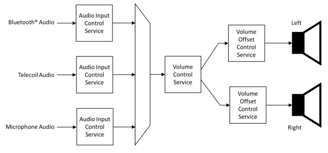
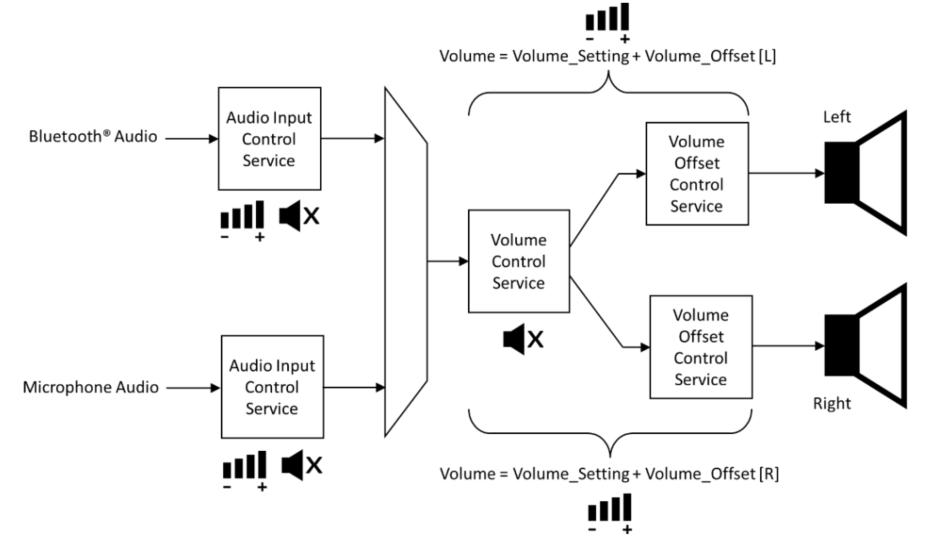
The diagram above shows a typical implementation of a pair of Server or BLE hearing aids with three possible audio input-Bluetooth audio streaming, Telecoil audio input and microphone input. These inputs are mixed together and their respective gains are set through the Audio Input Control Service and selectively muted and unmuted. The gain of the resulting stream is controlled by the Volume Control Service. If the audio stream is stereo, once split into left and right channel components, separate instances of the volume offset control service can independently adjust the gain fed into each speaker. (The diagram is a hardware representation. In reality, the sum of the VCS and VOCS gain settings is applied to each audio channel.) Used together in different ways, they simulate the effect of a balance control. They can also be used individually to adjust the relative sound levels in each speaker for different degrees of hearing loss in left and right ears.
Volume Initialization
MICS Initialization
Register Client-side and Server-side functions:
void blc_audio_registerMICSControlClient(const blc_micsc_regParam_t *param);
void blc_audio_registerMICSControlServer(const blc_micss_regParam_t *param);
Server parameter: Microphone state to be initialized. With a null pointer, the default configuration is the parameter defined by defaultMicpParam. The microphone state is defined as follows:
typedef enum{
MICS_MUTE_VALUE_NOT_MUTED = 0x00,
MICS_MUTE_VALUE_MUTED,
    MICS_MUTE_VALUE_DISABLED,
    MICS_MUTE_VALUE_RFU,
} blc_mics_mute_value_enum;

typedef struct{
    blc_mics_mute_value_enum mute;
} blc_micss_regParam_t;

const blc_micss_regParam_t defaultMicpParam =
{
    .mute = MICS_MUTE_VALUE_NOT_MUTED,
};
VCS/AICS/VOCS Initialization
When the SDK is designed, AICS may be included in both MICS and VCS, and the initialization of AICS parameters will be completed when VCS is initialized. And the default AICS of SDK can not be included only by MICS while not by VCS, the control of AICS can only be achieved through VCS.
Register Client-side and Server-side functions:
void blc_audio_registerVCSControlClient(const blc_vcsc_regParam_t *param);
void blc_audio_registerVCSControlServer(const blc_vcss_regParam_t *param);

#define VCS_DEFAULT_STEP                1
#define VCS_DEFAULT_VOLUME          20

#define AICS_INPUT_DESC_1               "Telink AICS Input Description 1"
#define VOCS_OUTPUT_DESC_1              "Telink VOCS Output Description 1"

static const blc_aicss_regParam_t defaultAicsParam[APP_AUDIO_VCS_INCLUDE_AICS_INSTANCE_NUM] = {
#if APP_AUDIO_VCS_INCLUDE_AICS_INSTANCE_NUM > 0
    {
        .gainSetting = 1,
        .mute = AICS_MUTE_VALUE_MUTED,
        .gainMode = AICS_GAIN_MODE_VALUE_MANUAL,
        .units = 1,
        .minGain = -128,
        .maxGain = 127,
        .inputType = AICS_INPUT_TYPE_DIGITAL,
        .inputStatus = AICS_INPUT_STATUS_ACTIVE,
        .desc = AICS_INPUT_DESC_1,
    },
#endif
......
};

static const blc_vocss_regParam_t defaultVocsParam[APP_AUDIO_VCS_INCLUDE_VOCS_INSTANCE_NUM] = {
#if APP_AUDIO_VCS_INCLUDE_VOCS_INSTANCE_NUM > 0
    {
        .location = BLC_AUDIO_LOCATION_FLAG_FL,
        .volumeOffset = 2,
        .desc = VOCS_OUTPUT_DESC_1,
    },
#endif
......
};

const blc_vcss_regParam_t defaultVcpRendererParam = {
    .vcsParam = {
        .step = VCS_DEFAULT_STEP,
        .volume = VCS_DEFAULT_VOLUME,
        .mute = false,
    },
    .aicsParam = defaultAicsParam,
    .vocsParam = defaultVocsParam,
};

const blc_micss_regParam_t defaultMicpParam =
{
    .mute = MICS_MUTE_VALUE_NOT_MUTED,
};
The following is Server structure parameters and related description. The structure mainly contains VCS parameters, AICS parameters and VOCS parameters, which are introduced in turn below.
typedef struct{
blc_vcs_regParam_t vcsParam;
    /* Register parameters for Audio Input Control Services(AICS) */
    const blc_aicss_regParam_t* aicsParam;
    /* Register parameters for Volume Offset Control Services(VOCS) */
    const blc_vocss_regParam_t* vocsParam;
} blc_vcss_regParam_t;
VCS Parameters
typedef struct{
u8 step;        //Volume Setting Change Step;1-255
    /* Volume State */
    u8 volume;      //Volume Setting
    bool mute;      //mute
} blc_vcs_regParam_t;
- step: Volume control stepper. This is due to the fact that the VCS specification has qualitative operations such as volume up and volume down, and the profile requires a stepper to control when performing these operations.
- volume: Volume value of the output, range [0,255].
- mute: Mute the output.
AICS Parameters
typedef struct{
/* Audio Input State */
    s8 gainSetting;         // Gain_Setting range(-128 to 127)
    u8 mute;        // mute blc_aics_mute_value_enum
    u8 gainMode;    //blc_aics_gain_mode_value_enum
    /* Gain Setting Properties */
    u8 units;       //Gain Setting Units, 0.1dB
    s8 minGain;     //Gain Setting Minimum >= -128
    s8 maxGain;     //Gain Setting Maximum <= 127, -128<=minGain<maxGain<=127
    /* Audio Input Type */
    u8 inputType;   //blc_aics_audio_input_type_def_enum
    /* Audio Input Status */
    u8 inputStatus; //blc_aics_audio_input_status_enum
    /* Audio Input Description */
    char *desc;
} blc_aicss_regParam_t;
- gainSetting: Input gain, range [-128,127].
- mute: Mute the input. Refer to the definition below:
typedef enum{
    AICS_MUTE_VALUE_NOT_MUTED = 0x00,
    AICS_MUTE_VALUE_MUTED,
    AICS_MUTE_VALUE_DISABLED,
    AICS_MUTE_VALUE_RFU,
} blc_aics_mute_value_enum;
- gainMode: Input Gain Mode. Refer to the definition below:
typedef enum{
    AICS_GAIN_MODE_VALUE_MANUAL_ONLY    = 0x00,
    AICS_GAIN_MODE_VALUE_AUTOMATIC_ONLY,
    AICS_GAIN_MODE_VALUE_MANUAL,
    AICS_GAIN_MODE_VALUE_AUTOMATIC,
} blc_aics_gain_mode_value_enum;
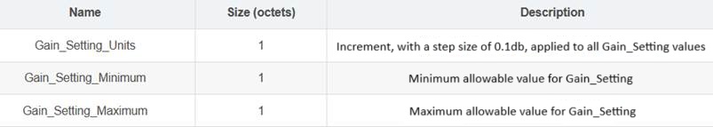
- units: Input gain stepper in 0.1 dB.
- minGain, maxGain: Input gain max and min value.
- inputType: Input Type. Refer to the audio input type definition. Defined in the SDK as follows:
typedef enum{
    AICS_INPUT_TYPE_UNSPECIFIED = 0x00, //Unspecified Input
    AICS_INPUT_TYPE_BLUETOOTH,          //Bluetooth Audio Stream
    AICS_INPUT_TYPE_MICROPHONE,         //Microphone
    AICS_INPUT_TYPE_ANALOG,             //Analog Interface
    AICS_INPUT_TYPE_DIGITAL,            //Digital Interface
    AICS_INPUT_TYPE_RADIO,              //AM/FM/XM/etc
    AICS_INPUT_TYPE_STREAMING,          //Streaming Audio Source
    AICS_INPUT_TYPE_RFU,
} blc_aics_audio_input_type_def_enum;
- inputStatus: Input status. Refer to the definition below:
typedef enum{
    AICS_INPUT_STATUS_INACTIVE = 0x00,
    AICS_INPUT_STATUS_ACTIVE,
    AICS_INPUT_STATUS_RFU,
} blc_aics_audio_input_status_enum;
VOCS Parameters
typedef struct{
    /* Volume Offset State */
    s16 volumeOffset;   //-255 to 255 MIN_VOLUME_OFFSET
    /* Audio Location */
    u32 location;   //BLC_AUDIO_CHANNEL_ALLOCATION_RFU
    /* Audio Output Description */
    char *desc;
} blc_vocss_regParam_t;
- volumeOffset: Output volume offset value, range [-255,255].
- location: Audio output location, refer to the audio location definition.
- desc: Output description, usually a utf-8 string.
Volume Operation
VCS Volume Usage
Client Side
Get the status of the Server:
audio_error_enum blc_vcsc_getVolState(u16 connHandle, blc_vcs_volume_state_t* state);
Set to not mute and reduce the relative volume:
ble_sts_t blc_vcsc_writeUnmuteOrRelativeVolDown(u16 connHandle);
Set to not mute and increase the relative volume:
ble_sts_t blc_vcsc_writeUnmuteOrRelativeVolUp(u16 connHandle);
Set the absolute volume:
ble_sts_t blc_vcsc_writeSetAbsoluteVol(u16 connHandle, u8 volSetting);
Set to not mute:
ble_sts_t blc_vcsc_writeUnmute(u16 connHandle);
Set to mute:
ble_sts_t blc_vcsc_writeMute(u16 connHandle);
Server Side
Update Server volume:
ble_sts_t blc_vcss_updateVolSetting(u16 connHandle, u8 volSetting);
Update Server mute status:
ble_sts_t blc_vcss_updateMuteState(u16 connHandle, bool mute);
Update Server volume status:
ble_sts_t blc_vcss_updateVolState(u16 connHandle, u8 volSetting, bool mute);
MICS Microphone Input Control
Client Side
Get mute status:
audio_error_enum blc_micsc_getMute(u16 connHandle, u8* mute);
Write to mute status:
ble_sts_t blc_micsc_writeMute(u16 connHandle, blc_mics_mute_value_enum mute, prf_write_cb_t writeCb);

typedef enum{
    MICS_MUTE_VALUE_NOT_MUTED = 0x00,
    MICS_MUTE_VALUE_MUTED,
    MICS_MUTE_VALUE_DISABLED,
    MICS_MUTE_VALUE_RFU,
} blc_mics_mute_value_enum;
Server Side
Update mute status:
ble_sts_t blc_micss_updateMute(u16 connHandle, blc_mics_mute_value_enum mute);

AICS Audio Input Control
A device may incorporate multiple audio input control services, primarily serving to initialize configurations for audio inputs (e.g., Bluetooth audio streams, microphones, etc.). Multiple audio inputs can be part of the audio mixing function. AICS is usually included by VCS or MICS, and the audio input type of an AICS included by MICS can only be a microphone. The SDK makes some simplifications in the Server section. It is assumed that AICS included in MICS is definitely also included in VCS, without considering devices that only have microphone input and no audio output. The Client side is a complete service, and AICS can be included by MICS or VCS alone, or by both MICS and VCS.
It is like a singer wearing an In-Ear Monitor, on the one hand, the singer can hear the background music of the band, whose volume can be adjusted, on the other hand, the singer can hear their own microphone, whose volume can also be adjusted. Working together, the two form a complete In-Ear Monitor, and users can adjust the output amplitude of any audio heard. But this technique requires audio mixing, which SDK does not support at the moment.
Client Side
Get audio input status:
audio_error_enum blc_aiscc_getAudioInputState(u16 connHandle, blc_aics_client_t* aicsc, blc_aics_audio_input_state_t* inputState);
Get gain settings:
audio_error_enum blc_aiscc_getGainSetProperties(u16 connHandle, blc_aics_client_t* aicsc, blc_aics_gain_setting_properties_t* gainSetProp);
Get audio input type:
audio_error_enum blc_aiscc_getAudioInputType(u16 connHandle, blc_aics_client_t* aicsc, u8 type[1]);

typedef enum{
    AICS_INPUT_TYPE_UNSPECIFIED = 0x00, //Unspecified Input
    AICS_INPUT_TYPE_BLUETOOTH,          //Bluetooth Audio Stream
    AICS_INPUT_TYPE_MICROPHONE,         //Microphone
    AICS_INPUT_TYPE_ANALOG,             //Analog Interface
    AICS_INPUT_TYPE_DIGITAL,            //Digital Interface
    AICS_INPUT_TYPE_RADIO,              //AM/FM/XM/etc
    AICS_INPUT_TYPE_STREAMING,          //Streaming Audio Source
    AICS_INPUT_TYPE_RFU,
} blc_aics_audio_input_type_def_enum;
Get audio input status:
audio_error_enum blc_aiscc_getAudioInputStatus(u16 connHandle, blc_aics_client_t* aicsc, u8 status[1]);

typedef enum{
    AICS_INPUT_STATUS_INACTIVE = 0x00,
    AICS_INPUT_STATUS_ACTIVE,
    AICS_INPUT_STATUS_RFU,
} blc_aics_audio_input_status_enum;
Get audio input description:
audio_error_enum blc_aiscc_getAudioInputDescription(u16 connHandle, blc_aics_client_t* aicsc, u8* desc, u16* descLen);
MIC follows the same procedure, see SDK for API.
Write to the audio input control endpoint:
ble_sts_t blc_aicsc_writeAudioInputControlPoint(u16 connHandle, blc_aics_client_t* aicsc, int opcode, s8 gainSetting, prf_write_cb_t writeCb);
Write the configured microphone gain value:
ble_sts_t blc_aicsc_writeSetGainSettingByMicpIndex(u16 connHandle, int index, s8 gainSetting);
Gain Setting exposes the current gain value in Gain Setting Units. Writing a value of 0 to the Mute will not affect the current Gain Setting value, so unmuting the Mute by writing a 1 to it will return the gain to the previous Gain Setting value, and if the Server is in Auto Gain Mode, it will ignore anything written to the Gain Setting field.
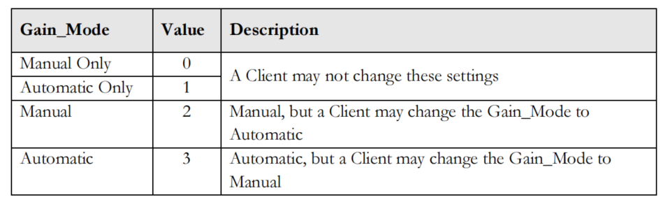
In more complex scenarios, the AICS enables audio streams to automatically regulate their gain (traditionally termed Automatic Gain Control, AGC) or be manually controlled, which can be achieved either by a volume control Client or locally by the user, with updated values exposed in the Audio Input Status. When the control is automatic, the Server does not support any change made by the Client, and the Server can expose whether the Client is allowed to change the mode from automatic to manual via the Gain Mode field of the Audio Input Status, using the values shown in the following figure, and vice versa,.
Set MIC to be unmuted via index:
ble_sts_t blc_aicsc_writeUnmuteByMicpIndex(u16 connHandle, int index);
Set MIC to mute via index:
ble_sts_t blc_aicsc_micpMute(u16 connHandle, int index);
Set MIC to manually adjust gain:
ble_sts_t blc_aicsc_micpSetManualGainMode(u16 connHandle, int index);
Set MIC to auto-adjust gain:
ble_sts_t blc_aicsc_micpSetAutoGainMode(u16 connHandle, int index);
Configure unacknowledged specification for input devices:
ble_sts_t blc_aiscc_writeInputDescWithoutRsp(u16 connHandle, blc_aics_client_t* aicsc, u8* desc, u16 descLen);
Configure acknowledged specification for input devices:
ble_sts_t blc_aiscc_writeMicpInputDesc(u16 connHandle, int index, u8* desc, u16 descLen);
Server Side
Update input state:
ble_sts_t blc_aicss_updateInputState(u16 connHandle, blc_aics_server_t *aicss, blc_aics_audio_input_state_t* inputState);
Update input status:
ble_sts_t blc_aicss_updateInputStatus(u16 connHandle, blc_aics_server_t *aicss, u8 status);
Update input description:
ble_sts_t blc_aicss_updateInputDesc(u16 connHandle, blc_aics_server_t *aicss, u8* desc, u16 descLen);
VOCS Volume Use
audio_error_enum blc_vocsc_getVolOffsetState(u16 connHandle, blc_vocs_client_t* vocsc, blc_vocs_volume_offset_state_t* state);

audio_error_enum blc_vocsc_getAudioLoc(u16 connHandle, blc_vocs_client_t* vocsc, u32* location);

ble_sts_t blc_vocsc_writeAudioLoc(u16 connHandle, blc_vocs_client_t* vocsc, u32 location);

ble_sts_t blc_vocsc_writeVolOffsetCtrlPoint(u16 connHandle, blc_vocs_client_t* vocsc, blt_vocs_volume_offset_control_opcode_enum opcode, s16 volOffset, prf_write_cb_t writeCb);
Volume Event Report
MICS Events
typedef enum{
    AUDIO_EVT_MICSC_START = AUDIO_EVT_TYPE_MICSC,
    AUDIO_EVT_MICSC_CHANGE_MUTE,    //refer to 'blc_micsc_muteChangeEvt_t'
} audio_micsc_evt_enum;
AUDIO_EVT_MICSC_CHANGE_MUTE:
An event reported by the MICS Client after it receives a report from the Server about the muted status of the microphone.
typedef enum{
    MICS_MUTE_VALUE_NOT_MUTED = 0x00,
    MICS_MUTE_VALUE_MUTED,
    MICS_MUTE_VALUE_DISABLED,
    MICS_MUTE_VALUE_RFU,
} blc_mics_mute_value_enum;
VCS Events
typedef enum{
    AUDIO_EVT_VCSC_START = AUDIO_EVT_TYPE_VCSC,
    AUDIO_EVT_VCSC_CHANGED_VOLUME_STATE,  //refer to 'blc_vcsc_volumeStateChangeEvt_t'
} audio_vcsc_evt_enum;
AUDIO_EVT_VCSC_CHANGED_VOLUME_STATE
typedef struct{
    u8   volumeSetting;
    bool mute;
} blc_vcsc_volumeStateChangeEvt_t;
-
volumeSetting: volume state
- Maximum value: 0xFF
- Minimum: 0x00
-
Mute: mute state
- Output mute: true
- Output unmute: false
AICS Events
typedef enum{
    AUDIO_EVT_AICSC_START = AUDIO_EVT_TYPE_AICSC,
    AUDIO_EVT_AICSC_CHANGED_INPUT_STATE,
} audio_aicsc_evt_enum;
AUDIO_EVT_AICSC_CHANGED_INPUT_STATE
typedef struct{
    u8 vcpInclIdx;
    u8 micpInclIdx;
    s8 gainSetting;
    u8 mute; //blc_aics_mute_value_enum
    u8 gainMode; //blc_aics_gain_mode_value_enum
} blc_aicsc_inStateChangeEvt_t;
VOCS Events
typedef enum{
    AUDIO_EVT_VOCSC_START = AUDIO_EVT_TYPE_VOCSC,
    AUDIO_EVT_VOCSC_CHANGED_VOLUME_OFFSET,
    AUDIO_EVT_VOCSC_CHANGED_LOCATION,
    AUDIO_EVT_VOCSC_CHANGED_OUTPUT_DESCRIPTION,
} audio_vocsc_evt_enum;
AUDIO_EVT_VOCSC_CHANGED_VOLUME_OFFSET
typedef struct{
    u8 vocsIndex;
    s16 volumeOffset;
} blc_vocsc_volumeOffsetStateChangeEvt_t;
- vocsIndex: The index number at which the VOCS is contained by the VCP;
- volumeOffset: Volume offset status value, the range is [-255,255].
AUDIO_EVT_VOCSC_CHANGED_LOCATION:
The event reported by the VOCS Client after it receives the audio location reported by the Server.
typedef struct{
    u8 vocsIndex;
    u32 location;
} blc_vocsc_locationChangeEvt_t;
AUDIO_EVT_VOCSC_CHANGED_OUTPUT_DESCRIPTION
typedef struct{
    u8 vocsIndex;
    u16 descLen;
    u8* desc;
} blc_vocsc_outputDescChangeEvt_t;
- vocsIndex: The index number at which the VOCS is contained by the VCP.
- descLen: Audio output description length.
- desc: Audio output description, usually in utf-8 format.
USB
Telink USB supports the standard USB1.1 protocol, supporting both low-speed and full-speed data transfer modes. It requires external power supply, with the DM and DP pins multiplexed with GPIO ports (DM-PA5, DP-PA6). If users do not need the USB function, they can also use the DM and DP pins as normal GPIO interfaces. Supported device types include UDB, AUD, CDC, HID, USR.
Telink USB has a total of 9 endpoints, endpoint 0 can be used as both input and output, the other endpoints can only be used as unidirectional input or output. Endpoint 0 can only be used for transmission control, including build phase, data phase and status phase. User can use the endpoint bNumEndpoints in the interface descriptor to configure the current number of endpoints supported by the interface. Telink USB uses 8+256 bytes of USB-only memory to cache the data of each endpoint. Endpoint 0 only supports 8 bytes, and the rest of the endpoints share 256 bytes.
USB Data Sending and Receiving Process
Data Sending
Only endpoints with the input (Device -> Host) function can send data. First of all, the user should determine the busy state of the corresponding port through reg_usb_ep_ctrl(i) when sending data. If the port is busy, no information can be sent. If the port is idle, then reset the port first, and then write data into the port data register through reg_usb_ep_dat(i). The length of the data is controlled by the user, but do not exceed the maximum data length set in the port descriptor of the port. After filling in the data, change the port state to busy, and then the hardware transfers the data to the Host via an IN transaction and clears the busy state of the corresponding port.
Refer to the operation in the function int usbaudio_hid_report(u8 report_id, u8 *data, int cnt):
int usbaudio_hid_report(u8 report_id, u8 *data, int cnt){
    ...
    if(usbhw_is_ep_busy(USB_EDP_KEYBOARD_IN)){
    ...
    }
    reg_usb_ep_ptr(USB_EDP_KEYBOARD_IN) = 0;
    reg_usb_ep_dat(USB_EDP_KEYBOARD_IN) = report_id;
    foreach(i, cnt){
        reg_usb_ep_dat(USB_EDP_KEYBOARD_IN) = data[i];
    }
    reg_usb_ep_ctrl(USB_EDP_KEYBOARD_IN)=FLD_EP_DAT_ACK| (edp_toggle[USB_EDP_KEYBOARD_IN] ? FLD_USB_EP_DAT1 : FLD_USB_EP_DAT0);  // ACK
    edp_toggle[USB_EDP_KEYBOARD_IN] ^= 1;
    return 1;
}
Data Receiving
Only ports with the output (Host -> Device) function can receive data. Upon receiving data, the device must first use reg_usb_ep_ptr(i) to get the endpoint register's address and read its value to determine the received data length, and then set the register to 0. Then, it cyclically reads reg_usb_ep_dat(i) to get the received data, and stores the data into the received data buffer, and finally, it sets the ack state of the corresponding endpoints to 1 by operating reg_usb_ep_ctrl(i).
Refer to the operation in function void app_usb_irq_proc (void):
if (usbhw_get_eps_irq()&FLD_USB_EDP6_IRQ)
{
    u8 usbData[256];
    unsigned char len = reg_usb_ep6_ptr;
    usbhw_reset_ep_ptr(USB_EDP_SPEAKER);
    for (unsigned int i=0; i<len; i++)
    {
        usbData[i] = reg_usb_ep6_dat;
    }
    tlk_buffer_write(usbData,len,TLK_BUFFER_1);
    usbhw_data_ep_ack(USB_EDP_SPEAKER);
    usbhw_clr_eps_irq(FLD_USB_EDP6_IRQ);
}
Client USB
The USB of the LE Audio CIS Demo Client primarily serves as an isochronous audio endpoint. With 224 bytes (192+32 bytes) allocated to Speak and MIC, the remaining bandwidth is available for HID operations. The HID is enabled by default in the SDK and readily available for user implementation.
USB Initialization
void blc_audio_usb_init(void)
The function defines the initialization of the USB, sets the buffer size of the endpoints, the initialization of the pins, and the HID callback.
Handling of USB Commands
void usb_handle_irq(void)
The function describes the processing of USB commands, including endpoint setup, data, state and intf, almost all the processing of USB standard commands are here. User-specific data processing can be implemented here as needed. SDK integrates a callback function to process commands: int my_hid_report_cb(u8 *ps, int len).
app_usb_handle_set_intf
The function is used to process the Speak and MIC switch commands issued by the host side. With this command, it is possible to know if the host side has operated on Speak and MIC.
void my_app_cmd_rcvd(u8 cmd, u8 data)
Actively report some defined HID operations to the host side. The device side reports what time the host should poll the device for HID information during initialization, and this event is set through the descriptor.
Handling of USB ISO
void app_usb_irq_proc (void)
The function processes the ISO data, including the output of speak and the input of MIC.
Client Boot USB
USB Initialization
void dfu_usb_init(u16 id)
The function defines the initialization of USB.
USB Data Processing
void dfu_usb_handle_irq(void)
The function processes USB commands and data.
int hid_output_handle(void)
The callback function handles flash state transitions, primarily utilizing USB for data transfer to burn the firmware into the chip's flash.
Refer to the Client USB Upgrade in chapter Firmware Upgrade.
Server USB
Server USB is mainly used to debug, and can also be used to move data. Server enumerates a UDB device, and implements two interfaces, UBG and VCD. UBG is mainly used to print log information, and can also be used to receive commands to debug the function, etc. Working with the host computer tool, VCD is mainly used for the graphical display of log.
USB Initialization
int tlkapi_debug_init(void)
The function defines the initialization of USB.
USB Data Processing
void udb_usb_handle_irq(void)
This function processes endpoint data, including setup, data, state and interface, as well as almost all standard USB commands. User-specific data processing can be implemented here as needed.
int myudb_hci_cmd_from_usb (void)
This function parses the received USB data.
UDB Printing Implementation
The SDK currently packages three interfaces for printing that can be used in different situations.
#define  my_dump_str_data(en,s,p,n)            if(en){usb_send_str_data(s,(u8*)(p),n);}
#define  my_dump_str_u32s(en,s,d0,d1,d2,d3)    if(en){usb_send_str_u32s(s,(u32)(d0),(u32)(d1),(u32)(d2),(u32)(d3));}
#define  my_dump_str_u8s(en,s,d0,d1,d2,d3)     if(en){usb_send_str_u8s(s,(u8)(d0),(u8)(d1),(u8)(d2),(u8)(d3));}
Sample interfaces are listed below:
(1) my_dump_str_data(APP_DUMP_EN, "free mem fail", &index, 1); (2) my_dump_str_u32s(APP_DUMP_EN,"usbaud_handle_set_feature_mute",id,mute, usbaud_mute, b);
VCD Debugging
(1) VCD initialization
TBD, will be updated in a future release.
(2) VCD enable
TBD, will be updated in a future release.
(3) VCD settings
TBD, will be updated in a future release.
(4) VCD debugging
TBD, will be updated in a future release.
UART
There are two Telink UARTs, UART0 and UART1. In order to facilitate debugging, SDK now integrates UART printing. In Client, the output of log must rely on UART, because USB has been used as USB ISO. SDK provides three kinds of debugging methods. The first one is traditional UART debugging, which uses hardware UART and can be used in interrupt, using the mechanism of DMA, with the baud rate of 1M. The second one is analog UART debugging, which is not recommended to be used in interrupt. The third is shell component UART, commonly used to debug functions.
By default, UART0 in Client is used to print system log, UART1 to send/receive UART normal data in the form of shell component. UART in Server is not used at present, but may be used as the interface for wired upgrade in the future. Please refer to the Telink driver documentation for the examples of sending and receiving UART data.
UART Communication Principle
In Telink UART, the data to be sent is firstly written into the TX buffer by the MCU or DMA of the chip, and then the UART module sends the data in the TX buffer to other devices through the TX pin. In the receiving device, the data is first written into the RX buffer via the RX pin of the UART module, and then the data is read by the MCU or DMA of the receiving device. If the chip's RX buffer is close to overflowing, the chip sends a signal via its RTS pin, which can be configured as either high level or low level, to the device to which it is connected, indicating that the device should stop sending data. Similarly, if the chip receives a signal through its CTS pin, it indicates that the other device's RX buffer is approaching overflow and the chip should stop sending data.
Hardware UART
In the driver manual, the baud rate when hardware UART uses DMA mode for transmission and reception can reach 2M. But under normal circumstances, for stability, we usually use the baud rate of 1M. Hardware UART DMA mode can be used in interrupt.
//Define UART TX pin : UART0(PA3 PB2 PD2), UART1(PC6 PD6 PE0)
typedef enum{
    UART0_TX_PA3 = GPIO_PA3,
    UART0_TX_PB2 = GPIO_PB2,
    UART0_TX_PD2 = GPIO_PD2,
    UART1_TX_PC6 = GPIO_PC6,
    UART1_TX_PD6 = GPIO_PD6,
    UART1_TX_PE0 = GPIO_PE0,
    UART_TX_NONE_PIN =0xfff,
}uart_tx_pin_e;

//Define UART RX pin : UART0(PA4 PB3 PD3), UART1(PC7 PD7 PE2)
typedef enum{
    UART0_RX_PA4 = GPIO_PA4,
    UART0_RX_PB3 = GPIO_PB3,
    UART0_RX_PD3 = GPIO_PD3,
    UART1_RX_PC7 = GPIO_PC7,
    UART1_RX_PD7 = GPIO_PD7,
    UART1_RX_PE2 = GPIO_PE2,
    UART_RX_NONE_PIN =0xfff,
}uart_rx_pin_e;
UART Enable Configuration (DMA TRX)
uart_reset(UART1);
    uart_set_pin(UART1_TX_PC6,UART1_RX_PC7);
    uart_cal_div_and_bwpc(baudrate, sys_clk.pclk*1000*1000, &div, &bwpc);
    uart_set_rx_timeout(UART1, bwpc, 12, UART_BW_MUL2);
    uart_init(UART1, div, bwpc, UART_PARITY_NONE, UART_STOP_BIT_ONE);
    uart_set_tx_dma_config(UART1, SHELL_UART_DMA_TX);
    uart_set_rx_dma_config(UART1, SHELL_UART_DMA_RX);
    uart_clr_tx_done(UART1);
    uart_set_irq_mask(UART1, UART_RXDONE_MASK);
    uart_set_irq_mask(UART1, UART_TXDONE_MASK);
    plic_interrupt_enable(IRQ18_UART1);
    core_interrupt_enable();
    uart_receive_dma(UART1, shell_buff.buffer, SHELL_BUFF_SIZE);
Analog UART
There is not much difference between analog UART and hardware UART, the only difference is that analog UART is not recommended to be used in interrupt, because the printing of analog UART will occupy CPU resources and affect timing.
UART Printing
The log printing implementation can be found in vendor/common/tlkapi_debug.c and tlkapi_debug.h.
#define TLKAPI_DEBUG_CHANNEL_UDB 1 //USB Dump
#define TLKAPI_DEBUG_CHANNEL_GSUART 2 //GPIO simulated UART
#define TLKAPI_DEBUG_CHANNEL_UART 3 //hardware UART

#ifndef TLKAPI_DEBUG_ENABLE
#define TLKAPI_DEBUG_ENABLE 0
#endif

#ifndef TLKAPI_DEBUG_CHANNEL
#define TLKAPI_DEBUG_CHANNEL TLKAPI_DEBUG_CHANNEL_UDB
#endif

void tlkapi_send_str_data (char *str, u8 *ph, u32 n);
void tlkapi_send_str_u8s (char *str, u8 d0, u8 d1, u8 d2, u8 d3);
void tlkapi_send_str_u32s (char *str, u32 d0, u32 d1, u32 d2, u32 d3);
int my_printf(const char *fmt, ...);
#define tlkapi_send_string_data(en,s,p,n) if(en){tlkapi_send_str_data(s,(u8*)
(p),n);}
#define tlkapi_send_string_u8s(en,s,d0,d1,d2,d3) if(en){tlkapi_send_str_u8s(s,(u8)(d0),(u8)(d1),(u8)(d2),(u8)(d3));}
#define tlkapi_send_string_u32s(en,s,d0,d1,d2,d3) if(en){tlkapi_send_str_u32s(s,(u32)(d0),(u32)(d1),(u32)(d2),(u32)(d3));}
#define tlkapi_printf(en,fmt, ...) if(en){my_printf(fmt, ##__VA_ARGS__);}
Example:
tlkapi_printf (1, "PC POWER ON\n", &last_status, 1);
BLT_APP_STR_LOG("[APP]adv mac", pExtAdvInfo->address, 6);
In stack/ble/profile/audio/common/audio_cfg.h, there are switches for each layer of logs, users can turn on the corresponding log as needed. Below are some examples:
///////////////// Audio profile debug log //////////////
#ifndef DBG_PRF_AUD_LOG
#define DBG_PRF_AUD_LOG                 1
#endif
#ifndef PRF_DBG_AUDIO_EN
#define PRF_DBG_AUDIO_EN                    1
#endif
#ifndef PRF_DBG_ASCS_EN
#define PRF_DBG_ASCS_EN                 1
#endif

#ifndef PRF_DBG_BASS_EN
#define PRF_DBG_BASS_EN                     1
#endif
Shell Component UART
The Shell Component functions as a data processor for UART transmission and reception content. It effectively addresses the complexity of UART debugging by enabling function debugging via common UART host computer. Additionally, this component can also output debug logs.
Shell Initialization
uart_init_log(1000000);
shell_init();
shellTask(&shell);
After the normal UART initialization, add shell initialization, and add task to main_loop. SDK has already integrated the shell, users only need to enable the macro definition to use the shell.
#define UART_SELECT_SHELL_ENABLE 1
Shell Usage
(1) Print the log
#define PRINTK(...)      trace(__VA_ARGS__)
#define LOG(...)        do{PRINT("[INF]: "__VA_ARGS__);}while(0)
#define LOG_ERR(...)    do{PRINT("[ERR]: "__VA_ARGS__);}while(0)
#define LOG_WAR(...)    do{PRINT("[WAR]: "__VA_ARGS__);}while(0)
Example:
PRINTK("ptcmd cmd error  \r\n ");
PRINTK(" %x ", buff[i]);
(2) Debug function
Under normal circumstances, the shell can be used to debug functions, as shown in the following example:
func(int i, char ch, char *str)
{
    printf("input int: %d, char: %c, string: %s\r\n", i, ch, str);
}
Definition: SHELL_EXPORT_CMD(func, func, test)
Input: letter>>func 666 'A' "hello world"
Output: input int: 666, char: A, string: hello world
This component is currently adapted to xcom, putty, etc., and other host software users can test their own.
Firmware Upgrade
Client/Server EVB Upgrade
(1) Users can open the BDT tool, click the Device option to select the corresponding EVB black box, next select the chip at the bottom as B91 (current version), then open the File option to select the corresponding firmware, and then they can directly download it.
(2) If the first download step fails, users can download again after completing the Activate operation.
(3) If the second step fails, users need to use the dupont cable to connect the 3.3, SWS and GND wires to the corresponding pins of the chip, and then perform the second step again after completing this connection (Note: At this time, it is necessary to disconnect the USB interface of the black box).
(4) If all the above steps fail, then please contact Telink FAE for technical support.

Client USB Upgrade
DFU Usage
After the Client calls the CMD_DFU operation to enter the boot loader, users only need to drag the firmware to the main.exe application program, then the firmware upgrade can be completed automatically, and the program will be reset automatically after the upgrade.
analog_write(0x3c, 0x4b);
cpu_sleep_wakeup_32k_rc(DEEPSLEEP_MODE, PM_WAKEUP_TIMER, clock_time() + SYSTEM_TIMER_TICK_1MS * 1000);
(1) USB DFU
Through analog_read, when the return value is 0x4d (set by analog_write(0x3c, 0x4b) in the application code), the USB DFU state is entered, and the USB host can find the USB device named "USB DFU". If no DFU command is received within 30 seconds, the device will restart again.
(2) Start application code
When the return value is not 0x4d, the bootloader will start the application code normally: it first performs an integrity check on the application code, and if the check passes, it jumps to the start up part of the application code.
If the integrity check fails, it will enter the USB DFU state.
The logs are as follows:
Telink(C)2022 USB iap tool
Powered by HIDAPI library
Usage: Drag DFU image file to this execute file !
OTA file size is 235124
Manufacturer String: Telink
Product String : USB DFU
[IAP]: flash unlock
[IAP]: Erase @ 0x00008000
[IAP]: Erase @ 0x00009000
[IAP]: Erase @ 0x0000a000
[IAP]: Erase @ 0x0000b000
......
[IAP]: Erase @ 0x00037000
[IAP]: Erase @ 0x00038000
[IAP]: Erase @ 0x00039000
[IAP]: flash check from 00008000, size 202356
[IAP]: Response CRC:41429222 local_crc:41429222
[IAP]: flash reboot
Firmware updated successfully !
After the upgrade is successful, the host computer will print Firmware updated successfully, and after 100 ms, the Client will reboot with the new firmware applied.
DFU Modification
Modify USB Descriptor
In usb_dbg/dfu_usbdesc.c, the device/config descriptors commonly used by USB can be modified.
Other commonly used strings can be modified with the following macros located in the dfu_usbdesc.h file:
#define MYDFU_STRING_VENDOR L"Telink"
#define MYDFU_STRING_PRODUCT L"USB DFU"
#define MYDFU_STRING_SERIAL L"TLSR9218"
The HID descriptor can be modified via "hid_report_descriptor1".
USB Data Reception
The USB stack is implemented through dfu_usb_handle_irq. When output data is detected, a callback to the usb_hid_output_req function is triggered, and the callback event is actually generated by the hid_output_handle function.
_attribute_ram_code_ int hid_ouput_handle(void)
{
    uint8_t data[64];
    if (reg_usb_ep_irq_status & EP_IRQ_HID_OUTPUT)
    {
        reg_usb_ep_irq_status = EP_IRQ_HID_OUTPUT;
        reg_usb_ep_ptr(EP_HID_OUTPUT) = 0;
        for (int i=0; i <  64; i++)
        {
            data[i] = reg_usb_ep_dat(EP_HID_OUTPUT);
        }
        reg_usb_ep_ctrl(EP_HID_OUTPUT) = 1;     //ACK
        extern void usb_hid_output_req(uint8_t *p_dat, int len);
        usb_hid_output_req(data, 64);
    }
    return 0;
}
Server Fixture Firmware Upgrade
TBD, will be updated in a future release.
Server Wireless App Upgrade
TBD, will be updated in a future release.
FLASH Address Assignment
Currently Server and Client are using 1M/2M flash in the SDK, the address assignment and common user saves are as follows. If you want to use bigger flash, please contact Telink technical support.
Server 1M Address Assignment
TBD, will be updated in a future release.
Server 2M Address Assignment
TBD, will be updated in a future release.
Client 1M Address Assignment
| Address | Size | Function |
|---|---|---|
| 0x00000000~0x00007FFF | 32KB | Bootloader |
| 0x00008000~0x00008FFF | 4KB | Firmware information(CRC32+size+version) |
| 0x00009000~0x000E0FFF | 830KB | Firmware |
| 0x000E1000~0x000E7FFF | 28KB | Reserved bit |
| 0x000EB000~0x000EBFFF | 4KB | CALIB_OFFSET_CAP_ADDR |
| 0x000EC000~0x000ECFFF | 4KB | FLASH_DONGLE_NAME |
| 0x000ED000~0x000EDFFF | 4KB | USER_CONST_BASE |
| 0x000EE000~0x000EEFFF | 4KB | SW version |
| 0x000EF000~0x000EFFFF | 4KB | HW version |
| 0x000F0000~0x000F3FFF | 16KB | Audio ATT SDP info |
| 0x000F4000~0x000F7FFF | 16KB | SMP pairing and key information area |
| 0x000F8000~0x000FBFFF | 16KB | Secure Boot descriptor |
| 0x000FC000~0x000FDFFF | 8KB | Reserved bit |
| 0x000FE000~0x000FDFFF | 4KB | Built-in capacitance calibration value |
| 0x000FF000~0x000FFFFF | 4KB | Bluetooth address |
Client 2M Address Assignment
| Address | Size | Function |
|---|---|---|
| 0x00000000~0x00007FFF | 32KB | Bootloader |
| 0x00008000~0x00008FFF | 4KB | Firmware information(CRC32+size+version) |
| 0x00009000~0x001DFFFF | 1880KB | Firmware |
| 0x001E1000~0x001E4FFF | 16KB | Reserved bit |
| 0x001E5000~0x001E5FFF | 4KB | CALIB_OFFSET_CAP_ADDR |
| 0x001E6000~0x001E6FFF | 4KB | FLASH_DONGLE_NAME |
| 0x001E7000~0x001E7FFF | 4KB | SW version |
| 0x001E8000~0x001E8FFF | 4KB | HW version |
| 0x001E9000~0x001E9FFF | 4KB | USER_CONST_BASE |
| 0x001EA000~0x001EBFFF | 8KB | Audio ATT SDP info |
| 0x001EC000~0x001EFFFF | 16KB | SMP pairing and key information area |
| 0x001F0000~0x001F7FFF | 32KB | SW align area |
| 0x001F8000~0x001FBFFF | 16KB | Secure Boot descriptor |
| 0x001FC000~0x001FDFFF | 8KB | Reserved bit |
| 0x001FE000~0x001FEFFF | 4KB | Built-in capacitance calibration value |
| 0x001FF000~0x001FFFFF | 4KB | Bluetooth address |
Flash Usage
Page read/write and Sector 4K erase of flash are operated with interrupt off, while other functions are not interrupt off. When flash operation is performed, it is necessary to turn off the interrupt.
Read data:
void flash_dread(unsigned long addr, unsigned long len, unsigned char *buf)
Write data:
void flash_page_program(unsigned long addr, unsigned long len, unsigned char *buf)
Flash erase:
void flash_erase_sector(unsigned long addr)
All definitions are stored in the drivers/B91/flash.c file of the SDK.
Voltage Detection
As a product, server side usually use the battery as the power supply, at this time it is necessary to know the status of the battery, the user needs to use the ADC to collect the voltage of the battery. In B91, the GPIOs supporting sampling are PB0-PB7/PD0-PD1, totaling 10 IO ports. In the SDK, Server uses PB3 as the sampling port.
Voltage Detection Initialization
(1) Initialization of the interface to be used:
void check_bat_init(void)
(2) Sample port initialization:
void adc_gpio_sample_init(adc_input_pin_def_e pin,adc_ref_vol_e v_ref,adc_pre_scale_e pre_scale,adc_sample_freq_e sample_freq)
Parameters:
- Pin: Pin Selection
- v_ref: Reference voltage selection, it is recommended to select only ADC_VREF_1P2V
- pre_scale: Pre-scale factor, it is recommended to select only ADC_PRESCALE_1F4
- sample_freq: Sample rate
(3) Setting the number of samples and removing useless data values:
#define ADC_BUF_SIZE    32
#define ADC_BUF_DELETE  8
(4) If DMA transmission is used:
- It is necessary to set DMA at initialization:
#define ADC_DMA_CHN DMA7
- It is necessary to configure DMA after adc_gpio_sample_init initialization:
adc_set_dma_config(ADC_DMA_CHN);
- In this case, it is also necessary to use the API with the DMA suffix: adc_get_voltage_dma() when getting the ADC value. The SAR_ADC can only use audio's FIFO1 (not FIFO0), and FIFO1 can't be used for SAR_ADC and audio at the same time, FIFO0 can only be used for audio.
audio_data_fifo1_path_sel(SAR_ADC_DATA_IN_FIFO,OUT_NO_USE);
Voltage Detection Usage
The usage block diagram is shown below:

When sampling manually (ADC_NDMA_MODE), only one adc_code can be acquired at a time, during which the ADC sampling function will be turned off, and it must be used in such a way that the time interval between successive acquisitions of the adc_code is greater than 2 sampling cycles(If it is 96 kHz, then the time is 10.4 \(\mu\)s).
- Get the sampled values and process them:
u16 adc_get_voltage(void)
The function samples every 15 ms (this data can be changed). The user turns on the switch and immediately samples and then turns off the switch. After 32 data are taken, the data are sorted, the first 8 data and the last 8 data are removed and the average value is taken (how many data are sampled and how many are removed can be decided by the user), then this average value is compared with the median (not necessarily the median, but the position in the middle), if the difference between the two is not too large, this means that this sampling is accurate, if the difference is too big, this means that this sampling is inaccurate, and the last value will be used as the sampling value.
- Obtain the corresponding battery voltage value:
void check_bat_state(void)
The function gets the corresponding battery voltage value, which exists as a member of a table with 101 units from 0 to 100. Every second, it gets the data after comparison, and it will take 5 consecutive readings and average the data, then compare the last value, if there is any change, then it will update and notify the Client or the phone. At the same time, it will detect whether the data obtained is on the warning line, if it is continuously on the warning line, then it will perform the corresponding operations: such as low battery alert, ultra-low battery shutdown, etc.
- State of charge:
void system_enter_charging(void)
The function enters the charging state. Once it enters the charging state, it will disconnect the ACL and enter the hibernation mode. An I/O port exists as a wake-up port through which the Server is woken up.
Voltage Detection Modification
Currently SDK supports one IO sampling, if the user needs multi-channel sampling, it is necessary to use the following code to switch the pin before using u16 adc_get_voltage(void).
adc_pin_config(ADC_GPIO_MODE, pin);
adc_set_diff_input(pin >> 12, GND);
Key Detection
In SDK, there are two main key detection modules, both on the Server side, Client side key detection is not introduced here, only as an experiment. The first set is a single key implementation, used for the TLSR9517 audio development board key implementation, the relevant code is stored in app_key.c and app_key.h; the second set is a matrix keyboard implementation, used for the TLSR9518 development board four-key operation, the relevant code is stored in app_ui.c and app_ui.h. Here is only an introduction to the first set of keys. For the second set, please refer to the SDK.
Key detection is currently implemented in the SDK with single-click, double-click, triple-click, and long-press for x seconds, which can satisfy a variety of user scenarios, and the key function is highly integrated, users only need to slightly change can be easily set.
Key Detection Initialization
(1) Initialize keys:
void key_init(void)
(2) Initialize keys and sets low-power PM trigger pins:
- Set the maximum number of keys:
#define KEY_NUM 3
- Set the key scan interval and press interval:
#define KEY_SCAN_INTERVAL     10000
#define KEY_CLICK_INTERVAL    500000
- Set the pins for the keys:
#define WAKEUP_PAD_ONKEY            GPIO_PB0
#define VOL_UP_KEY_PIN              GPIO_PB2
#define VOL_DOWN_KEY_PIN            GPIO_PB1
- Set the long press time:
#define KEY_LONG_PRESS_2S     4
#define KEY_LONG_PRESS_5S     10
- Configure key information and set trigger level:
key_ctl_t key_cfg[KEY_NUM] =
{
    {
        .pin = WAKEUP_PAD_ONKEY,
        .key_down_level = 0,
    },
......
};
Key Detection Usage
- Key scanning and triggering:
void key_task(void)
- Single-click, double-click, triple-click and long-press(2s):
void power_key_sclick_func(void)
void power_key_dclick_func(void)
void power_key_tclick_func(void)
void power_key_long_func(void)
void vol_up_key_sclick_func(void)
void vol_up_key_dclick_func(void)
void vol_up_key_tclick_func(void)
void vol_up_key_long_func(void)
void vol_down_key_sclick_func(void)
void vol_down_key_dclick_func(void)
void vol_down_key_tclick_func(void)
void vol_down_key_long_func(void)
Key Detection Modification
Currently 3 keys are used in the sdk, if users don't need that many:
Step 1: Modify the KEY_NUM number;
Step 2: Delete the corresponding pin macro definition;
Step 3: Delete the corresponding configurations in key_cfg;
Step 4: Delete the corresponding function and the configuration inside app_key_event_handle.
If users need to add keys, just reverse the steps above.
If users want to change the long-press time, it is necessary to change it inside the key_task, or modify the time in the header file macro definition, and then correspond to the task.
#define KEY_LONG_PRESS_2S     4
#define KEY_LONG_PRESS_5S     10
For the other definitions of the key, users please check the code: app_key.c and app_key.h.
LED Management
In order to unify lighting effects management in the SDK, Server-side has integrated a set of LED management program, which is highly integrated and can realize the desired functions without much modification. There is no similar operation in the Client side, just simply pull up and pull down, if users need, please refer to the Server side to implementation.
LED Initialization
Set the level at which the LED turns on:
#define LED_ON_LEVEL 1
Set the number of LED:
#define LED_NUM 3
Set the LED pins:
#define GPIO_LED_BLUE           GPIO_PD3
#define GPIO_LED_GREEN          GPIO_PD2
#define GPIO_LED_WHITE          GPIO_PD1
#define GPIO_LED_RED            GPIO_PD0
Set the LED status:
const led_flash_t led_flash_cfg[] =
{
    {STATE_OFF,             0,      0,          100,            0},
    {STATE_ON,              0,      5000000,    0,              0},
    {STATE_ON,              0,      500000,     100,            0},
    {STATE_BLINK,           5,      200000,     200000,             0},
    {STATE_BLINK,           2,      200000,     200000,         5000000},
    {STATE_BLINK,           1,      200000,     100000,         100000},
};
typedef struct {
    led_state state;    //led state
    unsigned int blink_cnt;   //blink count
    unsigned int on_time;       //led on times
    unsigned int off_time;      //led off times
    unsigned int interval_time; //led blink interval times
}led_flash_t;
typedef enum
 {
    STATE_OFF,
    STATE_ON,
    STATE_BLINK,
    STATE_BLINK_REPEAT
}led_state;
Parameters:
- State: turn on, turn off, blink x times, repeat blinking
- blink_cnt: blink count
- on_time: turn on time
- off_time: turn off time
- interval_time: interval between blinks
Initialization of LED:
void leds_init(void)
Set the power-on default LED state:
const led_config_t led_default_config[LED_NUM] = {
    {
        .led_pin = GPIO_LED_RED,
        .pattern.state = STATE_ON,
        .pattern.blink_cnt = 0,
        .pattern.on_time = 1000000,
        .pattern.off_time = 5000,
    },
......
};
LED Usage
LED Operation:
void leds_task(void)
Management of individual LED:
void set_led_state(led_index_t index, led_pattern_index_t led_pattern)
Parameters:
- Index: the corresponding LED
- led_pattern: LED mode
typedef enum
{
    LED_INDEX_RED = 0,
    LED_INDEX_GREEN,
    LED_INDEX_BLUE,
    LED_INDEX_MAX
}led_index_t;
typedef enum
{
    LED_PATTERN_LED_OFF = 0,
    LED_PATTERN_LED_ON,
    LED_PATTERN_LED_ON_500MS,
    LED_PATTERN_LED_FLASH_5_TIMES,
    LED_PATTERN_LED_FLASH_2_TIMES_IN_5S,
    LED_PATTERN_LED_FLASH_200MS,
    LED_PATTERN_LED_MAX_STATE,
}led_pattern_index_t;
Example:
set_led_state(LED_INDEX_RED, LED_PATTERN_LED_ON_500MS);
The function indicates that the red light is on for 500ms and off after 500ms.
set_led_state(LED_INDEX_BLUE, LED_PATTERN_LED_FLASH_2_TIMES_IN_5S);
The blue light will blink continuously twice every 5s interval with a switching time of 200ms each time.
LED Modification
If the user needs to modify the pattern of the LED, it is necessary to modify the LED mode and LED state setting at the same time, and then the desired scene can be configured directly with set_led_state.
Currently SDK supports three LED management, if the user does not need so much:
(1) It is necessary to modify the number of macro configurations:
#define LED_NUM 3
(2) Then delete the LED pre-configuration corresponding to the function led_default_config.
If users need to use more LED, then follow the reverse deletion process to increase the number of LED.
Product Test
Currently, the SDK provides production test commands for the Client, but the Server does not implement such commands.
USB UDB Command
The USB UDB command is the production test method used by the Server, while the Client does not support this method. Client's tools are USB HID and UART.
- Register command callbacks:
myudb_register_hci_debug_cb(my_debug_server);
After registering, the UDB command service can be used, please refer to the USB chapter for implementation.
- Handler function:
int my_debug_server(unsigned char *p, int len)
{
    if (p[0] != 0x11)
    {
        return 1;
    }
    switch (p[1])
    {
        case 0:
        break;
        case 1:
        break;
......
        default:
        break;
    }
    return 0;
}
There are no commands added to the Server production test at the moment. To be added.
- The host computer tool:

USB HID Command
- Register a callback:
register_usb_debug_report_cb (my_hid_report_cb);
- Handler function:
int  my_hid_report_cb(u8 *ps, int len)
{
......
    switch (cmd)
    {
        case (DFUCMD_REM | DFUCMD_REM_DFU):
        break;
......
        default:
        break;
    }
......
    usb_custom_hid_report_set (rsp, 31);
    return 0;
}
The handler function currently integrates the commands needed for Client production test, please refer to the xls table of Client production test commands for specific commands.
- The host computer tool:

UART Command
The UART production test currently integrates four functions, and these four functions can realize all the functions required by the Client production test.
#define UART_SELECT UART1_SHELL
#define UART_SELECT_SHELL_ENABLE   1
- Handler function:
void production_test_cmd(int cmd, int data)
void production_test_enter_exit(int cmd)
void production_test_set_mac(int cmd, int buf1, int buf2, int buf3, int buf4, int buf5, int buf6)
void production_test_set_emi(int cmd, int buf1, int buf2, int buf3, int buf4, int buf5)
UART production test currently integrates four functions, these four functions can realize all the functions required by Client production test, the specific commands please refer to the Client production test command xls table.
- The host computer tool:
Currently the UART host computer development is only tested on xcom and putty, the other software please users to test by themselves.

Other Commands
The SDK does not integrate other test tools and commands, which can be implemented by users.
Appendix
Connection Failure Types and Locating Solutions
TBD, will be updated in a future release.
Bandwidth Calculation Method Based on LE Audio CIS
Currently the SDK uses the LC3 CODEC protocol, the exact amount of data is shown below:

Bandwidth Calculation Method:
Take CIS interval 10ms as an example to calculate the bandwidth using BLE 2M.
(1) A standard BLE packet, in addition to data, needs to have preamble.access code, header, MICCRC total 120bits, using 2M PHY time is 60\(\mu\)s, which is fixed.
(2) The inter-frame interval is fixed at 150\(\mu\)s,and the interval between two subevent is at least 150\(\mu\)s.
(3) The exact length of each packet depends on the length of the data carried by the packet.
(4) In order to ensure the transmission quality, the number of retransmissions (number of subevent) per packet is recommended to be at least 3, based on experience.
(5) Whether it is a couple of ACLs, the bandwidth left for ACLs is at least 1.875ms.
Example:
Both uplink and downlink are 16k, 10ms, 16bits for example, after LC3 compression, the data length is 40bytes, then the time of a subevent is T=60\(\mu\)s+160\(\mu\)s+60\(\mu\)s+160\(\mu\)s+150\(\mu\)s+150\(\mu\)s=740\(\mu\)s, and the source of 160\(\mu\)s is: 40 bytes of data totaling 320bits, and the time when using 2M PHY is 160\(\mu\)s.

LE Audio CIS Demonstration SDK Resource Consumption
TBD