Telink Wi-Fi SDK Developer Handbook
SDK Getting Started Guide
This document is a development guide for the Wi-Fi SDK, applicable to the Telink TLSR9118 chip.
Introduction
The SDK Getting Started Guide introduces the basics of the SDK: how to setup the development environment, build the SDK and host drivers (if needed), and how to download and run the firmware.
The SDK file provided by Telink Semiconductor contains the following directories.
- Doc
- Software
- Toolchain
Setup the Development Environment
To build the TLSR9118 device firmware, it is recommended to use a 64-bit Linux PC. The Ubuntu 20.04 or higher is recommended. In the following sections, it is assumed that the user is using Ubuntu.
Install Linux Software Packages
To perform basic builds, install the following software packages.
$ sudo apt install build-essential libncurses-dev
$ sudo apt-get install libevent-dev libnl-3-dev libnl-genl-
3-dev
Toolchain
Extract the toolchain to the "/opt/" directory.
$ sudo tar xvf nds32le-elf-mculib-v5.tar.gz -C /opt/
By default, it is assumed that the toolchain path of the SDK is "/opt/nds32le-elf-mculib-v5/bin/". If the toolchain is extracted to other locations, the path must be changed accordingly using "make menuconfig" before continuing to build.

Python and Software Packages
Some steps in the build process involve running Python scripts. Install the following Python software packages.
$ sudo apt install python3-pip
$ pip install pycryptodome
$ pip install imgtool
Since these software packages are typically installed in the /home/{user}/.local/bin directory, the path must be added to the PATH variable.
Edit the ~/.bashrc file and add the following command line.
export PATH=$PATH:~/.local/bin
Another method is to create a folder named bin under the directory, and the Linux distribution will automatically add /bin and /.local/bin to the PATH.
Install the AICE Driver on Windows
To use JTAG for debugging, ensure that the AICE adapter is connected.
- Install the AICE driver
Terminal Application
A serial terminal application is required to:
- Download firmware via UART
- View console logs
Firmware Building
Directory Structure
The top directory of the SDK contains the following sub-directories.
| Directory | Description |
|---|---|
| api | Telink Wi-Fi APIs |
| app | Example applications |
| configs | Default configuration |
| hal | Hardware abstraction layer |
| include | Header files to be included |
| kernel | Kernel with FreeRTOS and FreeBSD |
| lib | Library modules that may be used |
| prebuilt | Libraries built using predefined configurations |
| scripts | Scripts related to building |
The TLSR9118 chip has a built-in ROM that contains some commonly used software components, such as the C library, operating system, WLAN driver, network library, and BLE controller-related interfaces. Some software components have been integrated into the ROM and specifically implemented, while in the released SDK, these components only provide header files.
Build
If using Telink IDE, the VS Code extension is recommended. Please note that compiling with VS Code requires downloading the "Telink development tools". For details on downloading the tool and compiling the SDK, please refer to the "Telink VS Code Extension" on the Telink documentation website. If using the command line, proceed as follows:
Use the make distclean command to clear residual files from the last build. It is best to clean the files before changing any configurations.
Select a suitable configuration file in the configuration directory as the starting point for the build. Build a bootloader that runs in RAM.
$ make distclean
$ make tlsr9xxxs_bl_ram_defconfig
$ make
This will generate wits.tlsrboot.ram.bin
Build a bootloader for firmware burning
$ make distclean
$ make tlsr9xxxs_bl_defconfig
$ make
This will generate wits.tlsrboot.bin
Build a Standalone mode firmware
$ make distclean
$ make tlsr9xxxs_defconfig
$ make
This will generate wits.mcuboot.bin
After the build process is complete, the wits.xxxx.bin file will be generated. The binary file name may be slightly different depending on the configuration used.
Modify Configuration
The build system is based on traditional Kconfig and Kbuild. If any configuration options need to be changed, run make menuconfig and navigate to the option that needs to be modified.
$ make menuconfig

Secure Boot
The secure boot is supported, allowing only verified firmware to boot.
For more information, please contact Telink Technical Support.
Flash Encryption
The flash encryption is supported to protect the firmware. Even if the firmware is burned into another TLSR9118 chip, it will remain unusable. The corresponding security credentials must be used to write to the eFuse.
For more information, please contact Telink Technical Support.
Building Host Driver
This section is only applicable to users who wish to connect the TLSR9118 as a Wi-Fi interface to the host platform via SDIO or USB.
If the TLSR9118 is connected to the host platform, the corresponding kernel driver must be installed and running on the host.
Build
Configuration File Selection and Setting
cd xiaohu-ax/
cp configs/cfg_xxx.mk cfg.mk
Since multiple platforms and configuration modes are supported, such as SDIO OOB mode, SDIO INT mode, USB mode, etc. Users should first select a configuration file based on their platform and requirements for compilation. The system provides default configuration files stored in the configs/ directory:
| Configuration file | Platform/SDIO mode |
|---|---|
| cfg_sdio_normal_fullhan.mk | Fullhan, 4 bit mode interrupt |
| cfg_sdio_normal_goke.mk | Goke, 4 bit mode interrupt |
| cfg_sdio_normal.mk | X86/X64, 4 bit mode interrupt |
| cfg_sdio_polling.mk | Linux PC, Polling mode |
| cfg_sdio_oob_int_goke.mk | Goke, OOB interrupt mode |
| cfg_usb.mk | X86/X64 USB mode |
Compile the sncmfmac.ko Driver
Although ARCH and CROSS_COMPILE are already configured in the file, the KDIR parameter needs to be explicitly specified according to the user's environment. Where KDIR=/home/apache/page/xxx is the specified location of the kernel.
make KDIR=/home/apache/page/linux-4.9
If KDIR is not specified, the system will use the default kernel KDIR, and the compiled driver will be suitable for running on X86/X64 platform.
make
Compile Application
make KDIR=/home/apache/page/linux-4.9 apps
There are currently two types of applications:
- 'sncm_cmd':Configure and control Wi-Fi via host commands.
- 'sncm_chn'(also known as TlsrChannel): Wi-Fi configuration and control are completed on the TLSR9118 side, obtaining Wi-Fi connection information via Channel.
- 'sample_link' is primarily used to synchronise network node information such as MAC address, IP address, etc., on the TLSR9118 side.
- 'sample_cli' is primarily used to send customer-defined information.
Download Image
To download the image, it is necessary to use the "Telink Burning and Debugging Tool (BDT)". For detailed instructions on using BDT, please refer to the "BDT Burning and Debugging Tool" document on the Telink documentation website.
Debugging
JTAG Debugging Using OpenOCD
Overview
The AndeShape AICE-MICRO is a JTAG debugging device based on FT2232H, compatible with AndeSight™ development kits and AndesCore V5 series, and supports the JTAG interface of OpenOCD.

Setup the Debugging Environment
Connect the JTAG interface to the TLSR9118 EVB board and power it on to activate the JTAG function.
The network topology is shown in the figure below.

Remote Debugging
(1) Run the openocd.exe daemon on the remote computer.
On the compilation server, install riscv32-elf-gdb using nds32le-elf-mculib-v5.
Use the following command for remote debugging:
/opt/nds32le-elf-mculib-v5/bin/riscv32-elf-gdb
target remote 10.12.7.102:1234
Note: The IP address 10.12.7.102 is the host address used to connect to JTAG, and 1234 is the target port.

Wi-Fi Software Development Guide
Overview
TLSR9118 provides a rich set of TLSR API interfaces for the application layer, enabling it to operate and control the WLAN driver. Through the TLSR API, developers can implement Wi-Fi-related functions such as creating STA/SoftAP, network scanning, network configuration, association, disassociation, and status queries, as shown in the following figure.

The following is a description of each functional module:
- Application: Users can perform secondary development based on the TLSR API.
- Demo APP: SDK-provided functional development examples.
- TLSR API: A generic interface provided by the SDK.
- IFCONFIG: Used to configure, control, and query network interfaces.
- LWIP: Network protocol stack.
- WPA SUPPLICANT (including HOSTAPD): Wi-Fi management module.
- WLAN Driver: The module implementing the 802.11 network protocol.
- HW: Hardware implementation of WLAN.
Wi-Fi Loading
Overview
After the chip is powered on, the WLAN driver will automatically complete the loading process, perform initial configuration of registers, parameter calibration, and request and configure software resources.
Development Process
Step 1: After the chip is powered on, the WLAN automatically loads driver successfully.
Step 2: Refer to the sections Wi-Fi STA Function or Wi-Fi SoftAP Function.
Step 3: End
Precautions
The WLAN driver automatically loads the software resources required for wlan0 and wlan1 by default.
Wi-Fi STA Function
Overview
The STA provides the following functions:
- Configure the necessary resources for STA in WPA_SUPPLICANT
- Basic and advanced network scanning
- Network association
- DHCP function
- Query the status of the associated AP
- Disassociate
Development Process
Usage Scenario
When it is necessary to connect to a network and communicate with it, the STA function should be started.
STA API Functions
The API interfaces provided by the STA functions are listed in the table below:
| API Name | Description |
|---|---|
| tlsr_wifi_sta_start | Start STA. |
| tlsr_wifi_register_event_callback | Register event callback function of the STA interface. |
| tlsr_wifi_unregister_event | Unregister event callback function of interface. |
| tlsr_wifi_event_send | Send registered event to host (optional function). |
| tlsr_wifi_sta_scan | Trigger the STA to scan AP. |
| tlsr_wifi_sta_advance_scan | Scan based on specific parameter values. |
| tlsr_wifi_sta_scan_results | Get STA scan results. |
| tlsr_wifi_sta_set_config | Configure Wi-Fi connection information in STA mode. |
| tlsr_cli_sta_reconnect_policy | Set automatic reconnection configuration in STA mode. |
| tlsr_wifi_sta_connect | Execute STA connection. |
| tlsr_wifi_sta_get_connect_info | Get network status of the connected STA. |
| tlsr_wifi_sta_get_ap_rssi | Get the Received Signal Strength Indicatio(RSSI) value of router. If not connected, returns 0xFF. |
| netifapi_dhcp_start | Start DHCP Client and obtain IP address. |
| netifapi_dhcp_stop | Stop DHCP Client. |
| tlsr_wifi_sta_disconnect | Execute STA disconnection. |
| tlsr_wifi_sta_fast_connect | Execute STA fast connect for WPA/WPA2 encrypted routers. |
| tlsr_cli_sta_get_psk | Get pre-shared key (PSK) information for fast connect. |
| tlsr_wifi_sta_stop | Stop STA. |
| tlsr_wifi_sta_set_ps | Set power save mode configuration in STA mode. |
| tlsr_wifi_sta_set_country_code | Set desired country code. |
| tlsr_wifi_sta_get_country_code | Get currently set country code. |
| tlsr_wifi_sta_set_keepalive | Enable/disable keep-alive function, send empty frames according to interval. |
| tlsr_wifi_wc_set_keepalive | Enable/disable the keep-alive function when the STA enters low-power mode. |
| wits_wifi_set_wc_bcn_loss_chk | Enable/disable the final check for beacon loss when the STA enters low-power mode. |
| wits_wifi_set_wc_port_filter | Enable/disable TCP/UDP port number filtering when the STA enters low-power mode. |
Implementation Process
The implementation steps are as follows:
Step 1: Call tlsr_wifi_register_event_callback to register the STA event callback function.
Step 2: Call tlsr_wifi_sta_start to start the STA.
Step 3: Perform STA scanning. You can choose to call tlsr_wifi_sta_scan or tlsr_wifi_sta_advance_scan.
Step 4: Obtain the scanning results via tlsr_wifi_sta_scan_results.
Step 5: [Optional] Call tlsr_cli_sta_reconnect_policy to set the automatic reconnection policy.
Step 6: Based on the scan results from Step 4, select an appropriate network and use tlsr_wifi_sta_set_config to configure the connection settings.
Step 7: Call tlsr_wifi_sta_connect to establish the network connection.
Step 8: After receiving the SYSTEM_EVENT_STA_CONNECTED event, you can call tlsr_wifi_sta_get_connect_info to query the network status.
Step 9: Call netifapi_dhcp_start to obtain an IP address.
Step 10: Call tlsr_wifi_sta_disconnect to disconnect.
Step 11: Call tlsr_wifi_sta_stop to turn off the STA.
Step 12: End
The API function return values are shown in the table below.
| Definition | Value | Description |
|---|---|---|
| WITS_OK | 0 | Execution successful |
| WITS_FAIL | -1 | Execution failed |
Precautions
Connection-related matters
- Event callback: It is necessary to execute the tlsr_wifi_register_event_callback function to clearly understand the events occurring in the STA and perform corresponding actions.
- Bandwidth support:
- In Wi-Fi 4 mode, this product supports BW40 and BW20.
- In Wi-Fi 6 mode, this product only supports BW20.
- Connection Interface: The connection uses a non-blocking interface. The success of the connection can be confirmed by receiving the SYSTEM_EVENT_STA_CONNECTED event.
- Direct Connection: If the parameters of the network to be connected are known, a connection can be initiated directly without the scanning process.
- Authentication Mode:
- The auth parameter of the tlsr_wifi_sta_fast_connect interface only supports the following authentication modes:
- TLSR_WIFI_SECURITY_WPAPSK
- TLSR_WIFI_SECURITY_WPA2PSK
- Based on alliance specifications and security considerations, the following authentication modes are not supported:
- WEP
- WPA2PSK + TKIP
- The auth parameter of the tlsr_wifi_sta_fast_connect interface only supports the following authentication modes:
Scanning-related matters
- Scanning uses a non-blocking interface. After the scan command is successfully issued, it is recommended to wait 1 second before getting the scan results, or wait for the SYSTEM_EVENT_SCAN_DONE event to confirm that the scan has completed.
- Specific scans can be performed by specifying parameters such as SSID, BSSID, Channel, etc. (refer to tlsr_wifi_sta_advance_scan)
Programming Example
Example: Implementing STA function for startup, association, getting network information and IP address.
#include <stdio.h>
#include <stdlib.h>
#include <string.h>
#include <hal/unaligned.h>
#include <hal/kernel.h>
#include <hal/wlan.h>
#include <hal/kmem.h>
#include "kernel.h"
#include "compat_if.h"
#include "if_media.h"
#include "sncmu_d11.h"
#include "fwil_types.h"
#include "fweh.h"
#include "scdc.h"
#include "task.h"
#include "FreeRTOS.h"
#include <net80211/ieee80211_var.h>
#include <wits_err.h>
#include <wits_log.h>
#include <wits_wifi.h>
#include <wits_event_loop.h>
#include <common.h>
#include <tlsr_wifi.h>
#define TLSR_NEED_DHCP_START(event) ((event)->event_info.connected.not_en_dhcp == false)
/* Network information to be connected, which can be selected during compilation or modified during execution. */
tlsr_wifi_assoc_request g_assoc_req = {
.ssid = "Xiaomi_7AB6", /* Network name */
.auth = TLSR_WIFI_SECURITY_WPA2PSK, /* Authentication mode */
.key = "12345678", /* Authentication Password  */
};
int tlsr_wifi_register_event_callback(system_event_cb_t event_cb, void *priv)
{
wits_event_loop_init(event_cb, priv);
return WITS_OK;
}
/* This function can receive necessary Wi-Fi-related events. */
wits_err_t event_handler(void *ctx, system_event_t * event)
{
switch (event->event_id) {
case SYSTEM_EVENT_STA_START:
break;
case SYSTEM_EVENT_STA_STOP:
break;
case SYSTEM_EVENT_STA_GOT_IP:
printf("\r\n WIFI GOT IP indicate\r\n");
break;
case SYSTEM_EVENT_AP_START:
break;
case SYSTEM_EVENT_AP_STOP:
break;
case SYSTEM_EVENT_AP_STADISCONNECTED:
break;
case SYSTEM_EVENT_STA_CONNECTED:
printf("\r\nWIFI CONNECTED indicate\r\n");
/* Connection successful, start DHCP client. */
if (TLSR_NEED_DHCP_START(event)) {
tlsr_wifi_status connect_status;
netifapi_dhcp_start(tlsr_wifi_get_netif(WITS_IF_WIFI_STA));
tlsr_wifi_sta_get_connect_info(&connect_status);
tlsr_wifi_sta_dump_ap_info(&connect_status);
}
break;
case SYSTEM_EVENT_STA_DISCONNECTED:
printf("\r\nWIFI DISCONNECT\r\n");
break;
case SYSTEM_EVENT_SCAN_DONE:
printf("WiFi: Scan results available\n");
break;
case SYSTEM_EVENT_TLSR_CHANNEL:
printf("WiFi: Tlsr channel send msg\n");
tlsr_wifi_event_send(event, sizeof(system_event_t));
break;
default:
break;
}
return WITS_OK;
}
int tlsr_wifi_start_connect(void)
{
tlsr_wifi_assoc_request *assoc_req = &g_assoc_req;
/* Configure Connection Information */
if (tlsr_wifi_sta_set_config(assoc_req, NULL))
return WITS_FAIL;
return tlsr_wifi_sta_connect();
}
int main(void)
{
int ret = WITS_OK;
char ifname[WIFI_IFNAME_MAX_SIZE + 1] = {0};
int len = sizeof(ifname);
printf("Sta Hello world!\n");
/* Register event callback function */
tlsr_wifi_register_event_callback(event_handler, NULL);
/* Enable STA function */
tlsr_wifi_sta_start(ifname, &len);
/* Start STA connection */
ret = tlsr_wifi_start_connect();
/* ret = 0 means execution is successful */
return ret;
}
Wi-Fi SoftAP Function
Overview
The SoftAP function mainly includes
- Configuring the necessary resources for SoftAP in WPA_SUPPLICANT
- Network configuration
- DHCP server function
- Querying the status of associated STA
- Disconnecting specified STA
Development Process
Usage Scenario
When it is necessary to create a network access point for other devices to connect and share network resources, the SoftAP function should be enabled.
SoftAP API Function
The API interfaces provided by the SoftAP function are listed in the table below.
| API Name | Description |
|---|---|
| tlsr_wifi_sap_start | Start SoftAP. Must first call tlsr_wifi_sap_set_config to configure the network. |
| tlsr_wifi_sap_stop | Stop SoftAP. |
| tlsr_wifi_register_event_callback | Register event callback function for the interface. |
| tlsr_wifi_unregister_event | Unregister event callback function for the interface. |
| tlsr_wifi_sap_set_config | Configure information required for SoftAP Wi-Fi connection. |
| tlsr_wifi_sap_get_config | Get the current configuration of SoftAP. |
| tlsr_wifi_sap_set_beacon_interval | Set the SoftAP beacon interval. |
| tlsr_wifi_sap_set_dtim_period | Set the SoftAP dtim period. |
| tlsr_wifi_sap_get_connected_sta | Get the current connected STA information. |
| tlsr_wifi_sap_deauth_sta | Disconnect specified STA's connection information. |
| tlsr_wifi_set_ip | Set the SoftAP's IP address, subnet mask, and gateway parameters. |
| tlsr_wifi_reset_ip | Clear the SoftAP's IP address, subnet mask, and gateway parameters. |
| netifapi_dhcps_start | Start DHCP Server. |
| netifapi_dhcps_stop | Stop DHCP Server. |
Implementation Process
The implementation steps are as follows:
Step 1: Call tlsr_wifi_register_event_callback to register the SoftAP event callback function.
Step 2: Call tlsr_wifi_sap_set_config to configure the SoftAP network parameters.
- Call
tlsr_wifi_sap_set_beacon_intervalto set the beacon interval. - Call
tlsr_wifi_sap_set_dtim_periodto set the dtim period. tlsr_wifi_sap_set_configwill automatically calltlsr_wifi_sap_stopandtlsr_wifi_sap_startto enable SoftAP.
Step 3: Call tlsr_wifi_sap_stop to close the previous SoftAP.
Step 4: Call tlsr_wifi_sap_start to restart SoftAP.
Step 5: Call tlsr_wifi_set_ip to configure the network IP.
Step 6: Call netifapi_dhcps_start to start the DHCP server.
Step 7: Call netifapi_dhcps_stop to stop the DHCP server.
Step 8: Call tlsr_wifi_sap_stop to close the SoftAP.
Step 9: End
The API function return values are shown in the table below.
| Definition | Value | Description |
|---|---|---|
| WITS_OK | 0 | Execution successful |
| WITS_FAIL | -1 | Execution failed |
Precautions
- To clearly understand the events occurring in the SoftAP and perform corresponding actions, it is necessary to execute the
tlsr_wifi_register_event_callbackfunction. - The network parameters of the SoftAP can be pre-set to default values.
- When SoftAP is closed, its network parameters are not reset, but after restarting the device, it will restore to the initial default values.
- SoftAP only supports OPEN and WPA2 modes.
- Under SoftAP mode, the maximum number of associated users can't be more than 1.
Programming Example
Example: Implementing SoftAP function startup, obtaining network information, and setting the IP address.
#include <stdio.h>
#include <stdlib.h>
#include <string.h>
#include <hal/unaligned.h>
#include <hal/kernel.h>
#include <hal/wlan.h>
#include <hal/kmem.h>
#include "kernel.h"
#include "compat_if.h"
#include "if_media.h"
#include "sncmu_d11.h"
#include "fwil_types.h"
#include "fweh.h"
#include "scdc.h"
#include "task.h"
#include "FreeRTOS.h"
#include <net80211/ieee80211_var.h>
#include <wits_err.h>
#include <wits_log.h>
#include <wits_wifi.h>
#include <wits_event_loop.h>
#include <common.h>
#include "dhcps.h"
#include <tlsr_wifi.h>
/* Network information that has been set, which can be selected during compilation or modified during execution. */
tlsr_wifi_softap_config g_sap_cfg = {
.ssid = "sap_test",
.key = "12345678",
.channel_num = 6,
.authmode = TLSR_WIFI_SECURITY_WPA2PSK,
.pairwits = TLSR_WIFI_PAIRWITS_AES,
};
wits_err_t event_handler(void *ctx, system_event_t * event)
{
switch (event->event_id) {
case SYSTEM_EVENT_AP_START:
printf("\r\nSYSTEM_EVENT_AP_START\r\n");
/* Set network IP */
tlsr_wifi_set_ip("wlan1", "192.168.200.1", "255.255.255.0", NULL);
/* Start DHCP Server */
netifapi_dhcps_start(tlsr_wifi_get_netif(WITS_IF_WIFI_AP));
break;
case SYSTEM_EVENT_AP_STOP:
printf("\r\nSYSTEM_EVENT_AP_STOP\r\n");
break;
case SYSTEM_EVENT_AP_STACONNECTED:
printf("\r\nSYSTEM_EVENT_AP_STACONNECTED\r\n");
printf("Connected STA:" MACSTR "\r\n",
MAC2STR(event->event_info.sta_connected.mac));
break;
case SYSTEM_EVENT_AP_STADISCONNECTED:
printf("\r\nSYSTEM_EVENT_AP_STADISCONNECTED\r\n");
printf("Disconnected STA:" MACSTR "\r\n",
MAC2STR(event->event_info.sta_disconnected.mac));
break;
default:
break;
}
return WITS_OK;
}
int main(void)
{
int ret = WITS_OK;
char ifname[WIFI_IFNAME_MAX_SIZE + 1] = {0};
int len = sizeof(ifname);
tlsr_wifi_softap_config *sap = &g_sap_cfg;
printf("SoftAP Hello world!\n");
/* Register event callback function */
tlsr_wifi_register_event_callback(event_handler, NULL);
/* Set SoftAP */
tlsr_wifi_sap_set_config(sap);
/* Start SoftAP */
ret = tlsr_wifi_sap_start(ifname, &len);
/* ret = 0 means execution successful */
return ret;
}
Wi-Fi STA/SoftAP Coexistence
Overview
The STA and SoftAP coexistence means that STA and SoftAP functions can operate simultaneously. Depending on the startup sequence of STA and SoftAP, the following scenarios can be distinguished:
| Scenario | Description |
|---|---|
| Same frequency, same band coexistence | Full-time coexistence |
| Same frequency, different band coexistence | Full-time coexistence |
| Different frequency, same band coexistence | Average Time-Sharing Coexistence |
| Different frequency, different band coexistence | Average Time-Sharing Coexistence |
Full-Time Coexistence: STA and SoftAP can operate simultaneously.
Time-Sharing Coexistence: STA and SoftAP operate during their respective time slots.
Development Process
Usage Scenarios
During network configuration, the product first starts the SoftAP. After the phone connects to the SoftAP, it sends home network information (such as SSID and password) to the product via the phone app. Upon receiving this information, the product starts the STA and connects to the home network. Once the product successfully connects, it closes the SoftAP and maintains only the STA connection to the home network. Other coexistence scenarios can be determined according to the product's specific requirements.
Implementation Process
Step 1: Create a SoftAP network interface (see the section Wi-Fi SoftAP Function).
Step 2: The phone connects to the SoftAP network and sends home network information via the phone app.
Step 3: [Optional] To avoid time-sharing coexistence, it is recommended to restart the SoftAP to the home network channel (see the section Wi-Fi SoftAP Function).
Step 4: Create an STA and complete the association based on the home network information (SSID and password) (see the section Wi-Fi STA Function).
Step 5: Close the SoftAP (see the section on Wi-Fi SoftAP Function).
Step 6: End
Return value: Please refer to the return value description for the corresponding module function.
Precautions
- In time-sharing coexistence mode, performance may be affected because STA and SoftAP need to take turns using the time slots. For better performance, it is recommended to set the SoftAP on the STA's working channel.
Programming Examples
Please refer to the programming examples in the sections Wi-Fi STA Function and Wi-Fi SoftAP Function.
Promiscuous Mode
Overview
The promiscuous Mode allows Wi-Fi hardware to capture all Wi-Fi frames on a specified channel and send raw 802.11 frames. This mode is critical for advanced network monitoring and troubleshooting.
Usage Scenarios
Usage Scenarios
By using the generic socket interface to capture raw Wi-Fi frames received by the hardware, this method provides higher consistency and reliability in data path applications compared to using callback registration.
Promiscuous Mode API Functions
The following is a list of API functions supported by Promiscuous Mode:
| API Name | Description |
|---|---|
| tlsr_wifi_set_promiscuous | Activate promiscuous mode for monitoring and capturing traffic. |
| tlsr_wifi_get_promiscuous | Check whether promiscuous mode is currently enabled. |
| tlsr_wifi_80211_tx | Send raw IEEE 802.11 data frames on the specified channel. |
| tlsr_wifi_set_channel | Configure primary/secondary channel for the device. |
| tlsr_wifi_get_channel | Get current primary/secondary channel information for the current device settings. |
Implementation Steps
Follow these steps to implement Promiscuous Mode:
(1) Enable promiscuous mode using tlsr_wifi_set_promiscuous.
(2) Configure the channel using tlsr_wifi_set_channel.
(3) Send raw 802.11 data frames using tlsr_wifi_80211_tx.
(4) Optional: Capture 802.11 data frames from the channel using a RAW socket for further analysis.
| Definition | Value | Description |
|---|---|---|
| WITS_OK | 0 | Execution successful |
| WITS_FAIL | -1 | Execution failed; check configuration and hardware status. |
Precautions
Operating Mode Notes
Before enabling promiscuous mode, ensure that STA and SoftAP modes are disabled. This can be achieved by executing the tlsr_wifi_sta_stop and tlsr_wifi_sap_stop commands. Only when promiscuous mode is activated, APIs such as tlsr_wifi_80211_tx and tlsr_wifi_set_channel will work properly.
Channel Settings in Monitor Mode
The RF channel must be set each time promiscuous mode is enabled. For example, the following sequence of operations is invalid:
(1) Enable promiscuous mode on wlan0.
(2) Set the channel for wlan0 to 1.
(3) Enable promiscuous mode on wlan1.
(4) Set the channel for wlan1 to 6.
(5) Send a raw 802.11 frame on wlan0, expecting it to be sent on channel 1.
Since the TLSR9118s has only one RF link, the setting in step 4 cover the previous channel setting, so the RF channel will be set to 6 in step 5.
Programming Examples
Example 1:
Send a raw 802.11 data frame to channel 6. For the specific implementation method, refer to the api/tlsr_cli_wifi.c file. Ensure that CONFIG_CLI_WIFI_CHANNEL and CONFIG_CLI_WIFI_MONITOR are enabled to use the relevant CLI commands.

Example 2:
Use the "wshark" command to display the received 802.11 raw data frame. Enable CONFIG_CMD_WSHARK before demonstrating this function.


Wi-Fi Frequently Asked Questions (FAQ)
TBD
Device Driver Development Guide
Introduction
The device driver development guide provides developers with a comprehensive guide, primarily introducing how to implement SoC (System on Chip) peripheral applications through the TLSR9118 device driver. The purpose of this document is to assist developers in fully leveraging the functions of the TLSR9118 Wi-Fi 6 and BLE 5 low-power SoC, with a particular emphasis on guiding developers on how to effectively utilize the device driver's application programming interfaces (APIs) and integrate them into applications with extremely high performance requirements.
Device Driver API
The TLSR9118 SDK provides two different levels of APIs:
-
Lower Layer API
- Code location: hal/drivers/xxxx/xxxx.c
- Header file location: include/hal/xxxx.h
- Functional purpose: These APIs primarily provide hardware abstraction functions, particularly direct access to hardware registers.
-
Application Layer API (TLSR API)
- Code location: api/tlsr_xxxx.c
- Header file location: api/include/tlsr_xxxx.h
- Functional features: The TLSR API aims to simplify access to functions through generic function calls that package calls to one or more Lower Layer APIs, operating system functions, and basic error handling.
Applications with Extremely High Performance Requirements
Although the TLSR API simplifies the development process by adding an abstraction layer above the lower layer API, this may introduce some performance overhead. In resource-intensive or time-sensitive applications, it is recommended to use lower layer APIs directly. For example, in custom circuit boards that need to communicate with external integrated circuits (ICs) via SPI and I2C interfaces simultaneously, it is recommended to develop a custom device driver specifically targeting SPI and I2C lower layer APIs. The application can interact directly with this custom driver instead of using the higher layer TLSR API.
Driver Event Notification Callback
In the TLSR9118 SDK, some peripherals may require some time to complete user-initiated operations. To address this, the SDK provides two types of APIs:
Synchronous APIs (tlsr_xxxx): These APIs include a timeout parameter and are suitable for scenarios where the application can wait for the operation to complete within a specified timeframe.
Asynchronous APIs (tlsr_xxxx_async): These APIs do not include a timeout parameter and are more suitable for scenarios where waiting for the operation to complete is not feasible. The completion status of these operations is communicated through a specific notification callback mechanism. When performing asynchronous operations, the completion notifications are delivered through callback functions. These callback functions are triggered during interrupt handling and should be executed quickly to avoid affecting the efficiency of interrupt handling. It is worth noting that due to the specific environment in which these callback functions run, the use of other APIs may be restricted. In most cases, synchronous APIs are recommended for simplicity and ease of integration.
Pin Control
Many peripherals in the SoC (System on Chip), such as SPI, I2C, GPIO, and PWM, require the use of specific pins.
Pin Mux Options
The available pin mux options are listed in the following file:
- File location: hal/drivers/pinctrl/pinctrl-tlsr9118.c
Each SoC pin can be configured as one of several predefined functions. For example, the pin mux options for UART0 and UART1 are as follows:
#ifdef CONFIG_USE_UART0
struct pinmux uart0_pin_mux[] = {
MUX("cts", 19, 3),
MUX("rts", 20, 3),
MUX("rxd", 0, 4),
MUX("rxd", 21, 0),
MUX("txd", 1, 4),
MUX("txd", 22, 0),
MUX("txd", 8, 4),
};
#endif
#ifdef CONFIG_USE_UART1
struct pinmux uart1_pin_mux[] = {
MUX("cts", 19, 4),
MUX("rts", 20, 4),
MUX("rxd", 0, 0),
MUX("rxd", 6, 4),
MUX("rxd", 17, 4),
MUX("txd", 1, 0),
MUX("txd", 7, 4),
MUX("txd", 8, 3),
MUX("txd", 18, 4),
};
#endif
Pin Mux Selection
The pin selection depends on the specific circuit board design, as each design uses pins in different ways. For example, in the TLSR9118 evaluation board, the UART pin selection is as follows, with the file location being:
- File location: hal/board/tlsr9118-evb-qfn40/board.c
static struct pinctrl_pin_map pin_map[] = {}
#ifdef CONFIG_USE_UART0
/* UART0 */
pinmap(21, "atcuart.0", "rxd", 0),
pinmap(22, "atcuart.0", "txd", 0),
#endif
#ifdef CONFIG_USE_UART1
/* UART1 */
pinmap( 0, "atcuart.1", "rxd", 0),
pinmap( 1, "atcuart.1", "txd", 0),
#endif
In general, the peripheral drivers, such as UART drivers, automatically request pin drivers to configure these pins for muxing.
UART
Overview
The TLSR9118 SoC supports communication with external devices using a Universal Asynchronous Receiver Transmitter (UART). The SoC provides three UART instances, one of which can be configured as a console to assist with firmware development.
API Functions
-
Initialization and Configuration:
- tlsr_uart_init(): Initializes the UART module.
- tlsr_uart_deinit(): Deinitializes the UART module.
- tlsr_uart_reset(): Resets the UART module.
-
Transmitter and Receiver:
- Data transmission: tlsr_uart_tx(), tlsr_uart_tx_async()
- Data reception: tlsr_uart_rx(), tlsr_uart_rx_async()
Development Guide
Configuration Structure
struct tlsr_uart_cfg {
enum tlsr_uart_buadrate buadrate;
enum tlsr_uart_data_bits data_bits;
enum tlsr_uart_parity parity;
enum tlsr_uart_stop_bits stop_bits;
uint8_t dma_en;
};
- baudrate: Set the baud rate (from 50 to 115200).
- data_bits: Set the data bit length (5, 6, 7, or 8 bits).
- parity: Configure odd-even parity (options: no parity, odd parity, even parity).
- stop bits: Set the stop bit length (1 bit or 2 bits).
- dma_en: Enable or disable DMA transfer.
Event Handling
- TLSR_UART_EVENT_TX_CMPL: Triggered when UART transmission is completed using the asynchronous API.
- TLSR_UART_EVENT_RX_CMPL: Triggered when UART reception is completed using the asynchronous API.
Transmission (Tx) and reception (Rx) operation steps:
(1) Initialise the UART according to the required configuration. (2) Transmit or Receive data to/from the connected devices. (3) Deinitialize the UART when it is no longer in use.
void sample_spi(void)
{
static struct tlsr_uart_cfg cfg = {
.buadrate = TLSR_UART_BDR_115200,
.data_bits = TLSR_UART_DATA_BITS_8,
.pairty = TLSR_UART_NO_PARITY,
.stop_bits = TLSR_UART_STOP_BIT_1,
.dma_en = 1,
};
int ret;
tlsr_uart_init(TLSR_UART_IDX_0, &cfg);
tlsr_uart_tx(TLSR_UART_IDX_0, tx_buf, tx_len, 1000);
tlsr_uart_rx(TLSR_UART_IDX_0, rx_buf, rx_len, 1000);
tlsr_uart_deinit(TLSR_UART_IDX_0);
}
Precautions
TBD
SPI (Serial Peripheral Interface)
Overview
The TLSR9118's SPI supports master and slave modes, enabling communication with external devices. It can be configured as standard SPI or quad-wire SPI (QSPI) for interfacing with devices that are compatible with quad-wire SPI.
The SPI master mode supports command, address, and data phases, and data can be transmitted without a command or address phase.
To receive or send data via SPI slave device, the peer master device must send an 8 bits command and 8 bits dummy data via a single IO before sending or receiving actual data.
API Functions
-
Initialization and Configuration:
tlsr_spi_init(): Initializes the SPI module.tlsr_spi_deinit(): Deinitializes the SPI module.tlsr_spi_configure(): Sets SPI parameters and options.tlsr_spi_reset(): Resets the SPI module.
-
Master Mode Operations:
- Data transmission:
tlsr_spi_master_tx(),tlsr_spi_master_tx_async() - Data reception:
tlsr_spi_master_rx(),tlsr_spi_master_rx_async() - Combined transmission and reception:
tlsr_spi_master_tx_rx(),tlsr_spi_master_tx_rx_async() - Command-based operations:
tlsr_spi_master_tx_with_cmd(),tlsr_spi_master_rx_with_cmd(), etc.
- Data transmission:
-
Slave Mode Operations:
- Buffer management:
tlsr_spi_slave_set_tx_buf(),tlsr_spi_slave_set_rx_buf(),tlsr_spi_slave_set_tx_rx_buf() - User state management:
tlsr_spi_slave_set_user_state()
- Buffer management:
Development Guide
Configuration
struct tlsr_spi_cfg {
enum tlsr_spi_role role;
enum tlsr_spi_mode mode;
enum tlsr_spi_data_io_format data_io_format;
enum tlsr_spi_bit_order bit_order;
enum tlsr_spi_dummy_cycle slave_extra_dummy_cycle;
uint32_t master_cs_bitmap;
enum tlsr_spi_clk_src clk_src;
uint8_t clk_div_2mul;
uint8_t dma_en;
}
-
role: select master mode or slave mode
-
mode: CPOL and CPHA mode
- TLSR_SPI_MODE_0: active high, odd edge sampling
- TLSR_SPI_MODE_1: active high, even edge sampling
- TLSR_SPI_MODE_2: active low, odd edge sampling
- TLSR_SPI_MODE_3: active low, even edge sampling
- data_io_format: select IO format
- SPI_DATA_IO_FORMAT_SINGLE
- SPI_DATA_IO_FORMAT_DUAL
- SPI_DATA_IO_FORMAT_QUAD
Note
- tlsr_spi_master_tx_rx and tlsr_spi_master_tx_rx_sync cannot be used in DUAL or QUAD IO format.
-
bit_order: select bit order
- SPI_BIT_MSB_FIRST
- SPI_BIT_LSB_FIRST
-
slave_extra_dummy_cycle
- TLSR_SPI_DUMMY_CYCLE_NONE
- TLSR_SPI_DUMMY_CYCLE_SINGLE_IO_8
- TLSR_SPI_DUMMY_CYCLE_SINGLE_IO_16
- TLSR_SPI_DUMMY_CYCLE_SINGLE_IO_24
- TLSR_SPI_DUMMY_CYCLE_SINGLE_IO_32
- TLSR_SPI_DUMMY_CYCLE_DUAL_IO_4
- TLSR_SPI_DUMMY_CYCLE_DUAL_IO_8
- TLSR_SPI_DUMMY_CYCLE_DUAL_IO_12
- TLSR_SPI_DUMMY_CYCLE_DUAL_IO_16
- TLSR_SPI_DUMMY_CYCLE_QUAD_IO_2
- TLSR_SPI_DUMMY_CYCLE_QUAD_IO_4
- TLSR_SPI_DUMMY_CYCLE_QUAD_IO_6
- TLSR_SPI_DUMMY_CYCLE_QUAD_IO_8
-
master_cs_bitmap: Bitmap of GPIO numbers to be used for chip-selects
-
clk_src: select SPI IO clock source
- SPI_CLK_SRC_XTAL: XTAL 40MHz
- SPI_CLK_SRC_PLL: PLL clock. SPI0 and SPI1 use 240MHz PLL clock, SPI2 uses 80MHz PLL clock
-
clk_div_2mul: source clock division value. Multiply the set value by 2 and then divide by this value. For example: clk_src = SPI_CLK_SRC_XTAL and clk_div_2mul = 20, the SPI IO clock is 1 MHz.
-
dma_en: enable or disable DMA transfer
Events
-
Master mode events
- TLSR_SPI_EVENT_MASTER_TRANS_CMPL: SPI transfer completion event. This event is triggered by the asynchronous API.
-
Slave mode events
- TLSR_SPI_EVENT_SLAVE_TX_REQUEST: Occurs when a read command is received.
- TLSR_SPI_EVENT_SLAVE_RX_REQUEST: Occurs when a read command is received.
- TLSR_SPI_EVENT_SLAVE_USER_CMD: Occurs when an undefined command is received.
- TLSR_SPI_EVENT_SLAVE_TRAN_CMPL: SPI transmission completion event.
Master mode usage steps:
- Step 1: Initialize SPI
- Step 2: Configure SPI as master mode
- Step 3: Send data to the slave device or receive data from the slave device
- Step 4: Deinitialize the SPI when it is no longer used
void sample_spi(void)
{
struct tlsr_spi_cfg cfg;
int ret;
memset(&cfg, 0, sizeof(cfg));
cfg.role = TLSR_SPI_ROLE_MASTER;
cfg.mode = TLSR_SPI_MODE_0;
cfg.data_io_format = TLSR_SPI_DATA_IO_FORMAT_SINGLE;
cfg.bit_order = TLSR_SPI_BIT_ORDER_MSB_FIRST;
cfg.clk_src = TLSR_SPI_CLK_SRC_XTAL,
cfg.clk_div_2mul = 20,
cfg.dma_en = 0,

tlsr_spi_init(tlsr_SPI_IDX_0);
tlsr_spi_configure(tlsr_SPI_IDX_0, &cfg, NULL, NULL);

tlsr_spi_master_tx(tlsr_SPI_IDX_0, tx_buf, tx_len, 1000);
tlsr_spi_master_rx(tlsr_SPI_IDX_0, rx_buf, rx_len, 1000);
tlsr_spi_master_tx_rx(tlsr_SPI_IDX_0, 0, tx_buf, tx_len, rx_buf, rx_len, 1000);

tlsr_spi_deinit(tlsr_SPI_IDX_0);
}
Slave mode usage steps:
- Step 1: Initialize SPI.
- Step 2: Configure SPI as slave mode.
- Step 3: Manage Tx/Rx buffers and respond to events.
- Step 4: Deinitialize SPI after use.
int volatile g_spi_complete;
void spi_slave_complete_wait(void)
{
g_spi_complete = 0;
while (1) {
if (g_spi_complete) {
}
}
}
Int spi_slave_notify(struct tlsr_spi_event *event, void *ctx)
{
Switch (event->type) {
case TLSR_SPI_EVENT_SLAVE_TRANS_CMPL:
g_spi_complete = 1;
break;
default:
break;
}
return 0;
}

void sample_spi(void)
{
struct tlsr_spi_cfg cfg;
int ret;
memset(&cfg, 0, sizeof(cfg));
cfg.role = TLSR_SPI_ROLE_SLAVE;
cfg.mode = TLSR_SPI_MODE_0;
cfg.data_io_format = TLSR_SPI_DATA_IO_FORMAT_SINGLE;
cfg.bit_order = TLSR_SPI_BIT_ORDER_MSB_FIRST;
cfg.clk_src = TLSR_SPI_CLK_SRC_XTAL,
cfg.clk_div_2mul = 20,
cfg.dma_en = 0,

tlsr_spi_init(TLSR_SPI_IDX_0);
tlsr_spi_configure(TLSR_SPI_IDX_0, &cfg, spi_slave_notify, NULL);

tlsr_spi_slave_set_tx_buf(TLSR_SPI_IDX_0, tx_buf, tx_len);
tlsr_spi_slave_complete_wait();

tlsr_spi_slave_set_rx_buf(TLSR_SPI_IDX_0, rx_buf, rx_len);
tlsr_spi_slave_complete_wait();

tlsr_spi_slave_set_tx_rx_buf(TLSR_SPI_IDX_0, tx_buf, tx_len, rx_buf, rx_len);
tlsr_spi_slave_complete_wait();

tlsr_spi_deinit(TLSR_SPI_IDX_0);
}
Precautions
-
SPI Instances: The TLSR9118 provides three SPI instances. The SPI0 is dedicated to flash memory and not used for other purposes.
-
DMA Usage: If using DMA, ensure that the transmit and receive buffers are located within an area where DMA is permitted.
-
Slave Mode Considerations: Notification functions in slave mode should be executed quickly to avoid transaction failures caused by master clock delays.
-
Support for multiple slave modes (as slave): The SPI driver should support multiple slave connection modes, such as enabling the CONFIG_SPI_SUPPORT_MULTI_SLAVES_AS_A_SLAVE configuration option for the atcspi driver to achieve this function.
- The master must insert sufficient dummy clock cycles between sending commands and data to ensure the slave has enough time to respond.
- The slave must configure the number of dummy clock cycles via the slave_extra_dummy_cycle parameter to match the master's settings.
- The number of dummy clock cycles is directly related to the SPI bus clock frequency; the faster the clock, the more dummy clock cycles are required.
-
Support for multiple slave modes (as master): The SPI driver should support multiple slave connection modes, such as enabling the CONFIG_SPI_SUPPORT_MULTI_SLAVES_AS_A_MASTER configuration option for the atcspi driver to achieve this function.
- The master must provide a GPIO bitmap for selecting slaves via the master_cs_bitmap parameter.
- Each bit in the bitmap corresponds to a GPIO pin used to control the chip select signal of a specific slave. For example, if GPIO0 and GPIO15 are used to control slave 1 and slave 2 respectively, the master_cs_bitmap should be configured as 0x00008001.
I2C (Inter-Integrated Circuit)
Function Description
The TLSR9118 SoC supports both master and slave modes of I2C, enabling communication with various external devices. The I2C interface is designed to handle standard data transfer protocols, ensuring compatibility with a wide range of I2C-compatible devices.
API Functions
-
Initialization and Configuration:
tlsr_i2c_init(): Initializes the I2C module.tlsr_i2c_deinit(): Deinitializes the I2C module.tlsr_i2c_configure(): Configures I2C parameters and options.tlsr_i2c_reset(): Resets the I2C module.
-
Master Mode Operations:
- Data transmission:
tlsr_i2c_master_tx(),tlsr_i2c_master_tx_async() - Data reception:
tlsr_i2c_master_rx(),tlsr_i2c_master_rx_async() - Combined transmission and reception:
tlsr_i2c_master_tx_rx(),tlsr_i2c_master_tx_rx_async() - Device detection:
tlsr_i2c_master_probe()
- Data transmission:
-
Slave Mode Operations:
- Transmit request:
tlsr_i2c_slave_tx() - Receive request:
tlsr_i2c_slave_rx()
- Transmit request:
Development Guide
Events
-
Master mode event
- TLSR_I2C_EVENT_MASTER_TRANS_CMPL: when the master completes the trasfer
-
Slave mode event
- TLSR_I2C_EVENT_SLAVE_RX_REQUEST: when the slave receives the RX (master to slave) data request
- TLSR_I2C_EVENT_SLAVE_TX_REQUEST: when the slave receives the TX (slave to master) data request
- TLSR_I2C_EVENT_SLAVE_RX_CMPL: when the slave completes the reception
- TLSR_I2C_EVENT_SLAVE_TX_CMPL: when the slave completes the transmission
Master mode usage steps:
- Step 1: Initialize I2C.
- Step 2: Configure I2C to master mode.
- Step 3: Perform transmit/receive operations.
- Step 4: Deinitialize I2C after use.
static int i2c_master_notify(struct tlsr_i2c_event *event, void *ctx)
{
return 0;
} v
oid sample_i2c(void)
{
struct tlsr_i2c_cfg cfg;
int ret;
memset(&cfg, 0, sizeof(cfg));
cfg.role = TLSR_I2C_ROLE_MASTER;
cfg.master_clock = 400 * 1000;
cfg.pull_up_en = 1;
tlsr_i2c_init(TLSR_I2C_IDX_0);
tlsr_i2c_configure(TLSR_I2C_IDX_0, &cfg, i2c_master_notify, NULL);
tlsr_i2c_master_tx(TLSR_I2C_IDX_0, SLAVE_DEVICE_ADDR, tx_buf, tx_len, 1000);
tlsr_i2c_master_tx_rx(TLSR_I2C_IDX_0, SLAVE_DEVICE_ADDR,
tx_buf, tx_len, buf, len, 1000);
tlsr_i2c_master_rx(TLSR_I2C_IDX_0, SLAVE_DEVICE_ADDR, buf, len, 1000);
tlsr_i2c_deinit(TLSR_I2C_IDX_0);
}
Slave mode usage steps:
- Step 1: Initialize I2C
- Step 2: Configure I2C to slave mode.
- Step 3: Prepare Tx or Rx data when the I2C notification function is called
- Step 4: Deinitialize I2C after use
Example:
static int i2c_slave_notify(struct tlsr_i2c_event *event, void *ctx)
{
switch (event->type) {
case TLSR_I2C_EVENT_SLAVE_TX_REQUEST:
tlsr_i2c_slave_tx(TLSR_I2C_IDX_1, tx_buf, tx_len);
break;
case tlsr_I2C_EVENT_SLAVE_RX_REQUEST:
tlsr_i2c_slave_rx(TLSR_I2C_IDX_1, rx_buf, rx_len);
break;
case TLSR_I2C_EVENT_SLAVE_TX_CMPL:
len = event->data.slave_tx_cmpl.len;
/* do something about tx data */
break;
case TLSR_I2C_EVENT_SLAVE_RX_CMPL:
len = event->data.slave_rx_cmpl.len;
/* do something about rx data */
break;
default:
break;
}
return 0;
}
void sample_i2c(void)
{
struct tlsr_i2c_cfg cfg;
int ret;
memset(&cfg, 0, sizeof(cfg));
cfg.role = TLSR_I2C_ROLE_SLAVE;
cfg.pull_up_en = 1;
tlsr_i2c_init(TLSR_I2C_IDX_0);
tlsr_i2c_configure(TLSR_I2C_IDX_1, &cfg, i2c_slave_notify, NULL);
...
tlsr_i2c_deinit(TLSR_I2C_IDX_1);
}
Precautions
For the slave mode, if the buffer provided by the user is insufficient,
- When the master attempts to read content beyond the buffer, 0 will be returned to the master.
- When the master attempts to write content beyond the buffer, the data will be silently discarded.
Timer
Overview
The TLSR9118 SoC is equipped with powerful timer function, providing two hardware timers. Each timer has four channels that can be configured in various modes, offering flexibility to create four independent timers to meet different application requirements.
Function Description
- tlsr_timer_configure: Configures the timer mode
- tlsr_timer_start: Starts the timer
- tlsr_timer_stop: Stops the timer
- tlsr_timer_start_multi: Starts multiple timers at the same time
- tlsr_timer_stop_multi: Stops multiple timers at the same time
- tlsr_timer_value: Reads the value of timer if it is configured as free-run mode
Development Guide
Perform the following steps:
- Step 1: Configure the timer
- Step 2: Start the timer
- Step 3: Read the timer
- Step 4: Stop the timer
Example:
static uint8_t timer_id[3] = { 0, 1, 2};
static int timer_notify(uint32_t pin, void *ctx)
{
uint8_t timer_id = *((uint8_t *)ctx);
/* differentiate the notification based on the context provided */
return 0;
} v
oid sample_timer(void)
{
struct tlsr_timer_cfg cfg0, cfg1, cfg2;
uint32_t value;
cfg0.mode = TLSR_TIMER_MODE_PERIODIC;
cfg0.intr_en = 1;
cfg0.data.periodic.duration = 1000000;
cfg1.mode = TLSR_TIMER_MODE_ONESHOT;
cfg1.intr_en = 1;
cfg1.data.oneshot.duration = 3000000;
cfg2.mode = TLSR_TIMER_MODE_FREERUN;
cfg2.data.freerun.freq = 1000000;
tlsr_timer_configure(TLSR_TIMER_IDX_0, TLSR_TIMER_CH_0, timer_notify, &cfg0,
&timer_id[0]);
tlsr_timer_configure(TLSR_TIMER_IDX_1, TLSR_TIMER_CH_1, timer_notify, &cfg1,
&timer_id[1]);
tlsr_timer_start(TLSR_TIMER_IDX_0, TLSR_TIMER_CH_0);
tlsr_timer_start(TLSR_TIMER_IDX_0, TLSR_TIMER_CH_1);
...
tlsr_timer_value(TLSR_TIMER_IDX_0, TLSR_TIMER_CH_2, &value);
...
tlsr_timer_stop_multi(TLSR_TIMER_IDX_0, 1 << TLSR_TIMER_CH_0 | 1 <<
TLSR_TIMER_CH_1);
}
Precautions
The TIMER1 instance is used by the power management and BLE subsystems. When power management (PM) or Bluetooth Low Energy (BLE) is enabled, the application should not use the index TLSR_TIMER_IDX_1 to call the timer API.
GPIO (General Purpose Input/Output)
Overview
The TLSR9118 SoC is equipped with 25 general purpose input/output (GPIO) pins. These GPIO pins can be configured as inputs or outputs, providing versatility for interfacing with external hardware and sensors.
API Functions
- Configuration and Control:
tlsr_gpio_configure(): Configures GPIO pins as inputs or outputs, including options for pull-up or pull-down resistors.tlsr_gpio_write(): Sets the output level of a GPIO pin.tlsr_gpio_read(): Reads the input level of a GPIO pin.tlsr_gpio_enable_interrupt(): Enables GPIO interrupts, supporting event-driven programming.tlsr_gpio_disable_interrupt(): Disables GPIO interrupts.
Development Guide
Basic steps for using GPIO:
- Step 1: Configure the GPIO pins for the desired input/output function.
- Step 2: For output usage, write the desired level to the GPIO pin.
- Step 3: For input usage, read the level from the GPIO pin as needed.
- Step 4: If using interrupts, enable them and provide a callback function to handle events.
Example code:
static int tlsr_cli_gpio_notify(uint32_t pin, void *ctx)
{
gpio_stats[pin]++;
return 0;
} v
oid sample_gpio(void)
{
/* set PIN 6 as gpio output */
tlsr_gpio_configure(6, TLSR_GPIO_PROP_OUTPUT);
tlsr_gpio_write(6, 1);
/* set PIN 7 as gpio input, and enable interrupt */
tlsr_gpio_configure(7, TLSR_GPIO_PROP_INPUT_PULL_DOWN);
tlsr_gpio_enable_interrupt(7, TLSR_GPIO_INT_BOTH_EDGE,
tlsr_cli_gpio_notify, NULL);
}
Precautions
- Power domain: GPIO pins 0 to 7 are located in the "always-on" power domain, which means they can maintain their state and receive wake-up events in low-power mode.
- Interrupt handling: Care should be taken to ensure that interrupt callback functions are efficient and do not block critical tasks.
eFuse
Function Description
The eFuse (electronically programmable fuse) of the TLSR9118 provides 1024 bits of non-volatile memory. This function is typically used to store critical system data, such as secure boot keys, device identity, and RF calibration data.
API Functions
- eFuse Operations:
tlsr_efuse_read(): Reads data from the specified eFuse address.tlsr_efuse_write(): Writes data to the specified eFuse address.
Development Guide
The reserved fields and their sizes are as follows.
#define TLSR_EFUSE_ADDR_ROOT_KEY 0
#define TLSR_EFUSE_SIZE_ROOT_KEY 128
#define TLSR_EFUSE_ADDR_PARITY 128
#define TLSR_EFUSE_SIZE_PARITY 1
#define TLSR_EFUSE_ADDR_HARD_KEY 129
#define TLSR_EFUSE_SIZE_HARD_KEY 1
#define TLSR_EFUSE_ADDR_FLASH_PROT 130
#define TLSR_EFUSE_SIZE_FLASh_PROT 1
#define TLSR_EFUSE_ADDR_SECURE_BOOT 131
#define TLSR_EFUSE_SIZE_SECURE_BOOT 1
#define TLSR_EFUSE_ADDR_AR_BL_EN 132
#define TLSR_EFUSE_SIZE_AR_BL_EN 1
#define TLSR_EFUSE_ADDR_SDIO_OCR_EN 132
#define TLSR_EFUSE_SIZE_SDIO_OCR_EN 1
#define TLSR_EFUSE_ADDR_AR_FW_EN 133
#define TLSR_EFUSE_SIZE_AR_FW_EN 1
#define TLSR_EFUSE_ADDR_CUST_ID 160
#define TLSR_EFUSE_SIZE_CUST_ID 8
#define TLSR_EFUSE_ADDR_CHIP_ID 192
#define TLSR_EFUSE_SIZE_CHIP_ID 32
#define TLSR_EFUSE_ADDR_PK_HASH 224
#define TLSR_EFUSE_SIZE_PK_HASH 256
#define TLSR_EFUSE_ADDR_SDIO_OCR 544
#define TLSR_EFUSE_SIZE_SDIO_OCR 20
#define TLSR_EFUSE_ADDR_WLAN_MAC_ADDR 576
#define TLSR_EFUSE_SIZE_WLAN_MAC_ADDR 48
#define TLSR_EFUSE_ADDR_BLE_MAC_ADDR 624
#define TLSR_EFUSE_SIZE_BLE_MAC_ADDR 48
#define TLSR_EFUSE_ADDR_RF_CAL 672
#define TLSR_EFUSE_SIZE_RF_CAL 64
#define TLSR_EFUSE_ADDR_AL_BL_VER 736
#define TLSR_EFUSE_SIZE_AL_BL_VER 64
#define TLSR_EFUSE_ADDR_RESERVED 800
#define TLSR_EFUSE_SIZE_RESERVED 224
Example:
uint8_t mac[8];
uint8_t custom_data[2];
void sample_efuse(void)
{
tlsr_efuse_read(TLSR_EFUSE_ADDR_WLAN_MAC_ADDR,
TLSR_EFUSE_SIZE_WLAN_MAC_ADDR,
mac);
tlsr_efuse_write(800, 16, &custom_data);
}
Precautions
Since the eFuse can only be written once, extra care must be taken when writing new values. Each bit of the eFuse can only change from 0 to 1 and cannot change reversely. In special cases, the same field can be written multiple times to set specific bits to 1.
ADC
Function Description
The TLSR9118 SoC is equipped with an Analog to Digital Converter (ADC) that can read analog voltage levels and convert them into digital format. The table below shows the correspondence between physical GPIO pins and corresponding ADC channels.
| ADC Channel | GPIO Pin |
|---|---|
| 4 | 4 |
| 5 | 7 |
| 6 | 0 |
| 7 | 1 |
API Function
- ADC measurement
- tlsr_adc_read(), tlsr_adc_read_aync(): Reads data from a specified ADC channel.
- tlsr_adc_reset(): Resets the ADC.
Development Guide
Example code:
static int adc_notify(void *ctx)
{
return 0;
} u
int16 ch0_buf[8];
uint16 ch1_buf[16];
void sample_efuse(void)
{
tlsr_adc_read(TLSR_ADC_SINGLE_CH_0, ch0_buf, 8);
tlsr_adc_read_async(TLSR_ADC_SINGLE_CH_1, ch1_buf, 16, adc_notify, NULL);
}
This example shows how to perform synchronous and asynchronous ADC reads. The tlsr_adc_read function is used for synchronous reads from channel 0, while tlsr_adc_read_async is used for asynchronous reads from channel 1, used in conjunction with callback functions.
Precautions
TBD
I2S (Inter-IC Sound)
Overview
The TLSR9118's I2S supports master-slave mode, enabling it to exchange audio sample data with an external audio CODEC. It supports multiple formats and word lengths, as described below.
API Functions
Initialization and Configuration:
tlsr_i2s_init(): Initializes the I2S module.tlsr_i2s_deinit(): Disables the I2S module.tlsr_i2s_configure(): Sets I2S parameters and options.tlsr_i2s_start(): Starts an I2S data stream in the specified direction.tlsr_i2s_stop(): Stops an I2S data stream in the specified direction.tlsr_i2s_read_block(): Reads an audio sample block from the I2S input stream and returns a success or error code.tlsr_i2s_write_block(): Writes an audio sample block to the I2S output stream and returns a success or error code.tlsr_i2s_get_block_buffer_size(): Returns the configured block buffer size.
Development Guide
Configuration
struct tlsr_i2s_cfg {
enum tlsr_i2s_wl word_length; // Number of bits per audio word (channel)
enum tlsr_i2s_fmt format; // I/O format
enum tlsr_i2s_role role; // Bus role (master/slave)
enum tlsr_i2s_direction dir; // Data transfer direction (Tx/Rx)
uint32_t fs; // Audio sampling frequency (Hz)
int duration_per_block; // Duration of each buffer block (milliseconds)
int number_of_blocks; // Maximum number of buffer blocks to allocate
int timeout; // Read/write timeout (milliseconds)
}
- word_length:
- TLSR_I2S_WL_16: 16 bits
- TLSR_I2S_WL_20: 20 bits
- TLSR_I2S_WL_24: 24 bits
Note
- 20 bits or 24 bits word length will occupy 32 bits in memory.
-
format: Select I/O format
- TLSR_I2S_FMT_I2S
- TLSR_I2S_FMT_LJ
- TLSR_I2S_FMT_RJ
-
role: Select bus role
- TLSR_I2S_ROLE_MASTER: Generate I2S bit clock and word clock.
- TLSR_I2S_ROLE_SLAVE
-
dir: Specify data transfer direction
- TLSR_I2S_RX
- TLSR_I2S_TX
-
fs: Audio sampling frequency (Hz)
-
duration_per_block: The duration (milliseconds) corresponding to each buffer block
Note
- Must be less than 1000 (1 second).
-
number_of_blocks: Maximum number of buffer blocks to allocate
-
timeout: Read/write timeout (milliseconds)
Transmission usage steps:
(1) Initialize I2S.
(2) Configure I2S to support Tx and Rx directions.
(3) Start the I2S stream in the Tx direction.
(4) Write audio sample blocks to the I2S Tx stream.
(5) Stop the Tx stream and stop the I2S module when no longer needed.
void sample_i2s_write(uint32 pattern)
{
   struct tlsr_i2s_cfg cfg;
   int bufsz;
   uint8_t *buf;

   tlsr_i2s_init();

   memset(&cfg, 0, sizeof(cfg));
   cfg.word_length = TLSR_I2S_WL_16;
   cfg.format = TLSR_I2S_FMT_I2S;
   cfg.role = TLSR_I2S_ROLE_MASTER;
   cfg.fs = 44100;
   cfg.duration_per_block = 100;
   cfg.number_of_blocks = 5;
   cfg.timeout = 3000;
   cfg.dir = TLSR_I2S_RX;
   tlsr_i2s_configure(&cfg);

   cfg.dir = TLSR_I2S_TX;
   tlsr_i2s_configure(&cfg);

   bufsz = tlsr_i2s_get_block_buffer_size(&cfg);
   buf = zalloc(bufsz);

   for (int i = 0; i < bufsz / 4; i = i + 4) {
     memcpy(buf + i, &pattern, sizeof(uint32_t));
   }

   tlsr_i2s_start(TLSR_I2S_TX);

   for (int i = 0; i < cfg.number_of_blocks; i++) {
     tlsr_i2s_write_block(buf, bufsz);
   }

   tlsr_i2s_stop(TLSR_I2S_TX);

   free(buf);

   tlsr_i2s_deinit();
}
Reception usage steps:
(1) Initialize I2S.
(2) Configure I2S to support Tx and Rx directions.
(3) Start the I2S stream in the Rx direction.
(4) Read audio sample blocks from the I2S Rx stream.
(5) Stop the Rx stream and stop the I2S module when no longer needed.
void sample_i2s_read(void)
{
  struct tlsr_i2s_cfg cfg;
  int bufsz, len;
  uint8_t *buf;

  tlsr_i2s_init();

  memset(&cfg, 0, sizeof(cfg));
  cfg.word_length = TLSR_I2S_WL_16;
  cfg.format = TLSR_I2S_FMT_I2S;
  cfg.role = TLSR_I2S_ROLE_MASTER;
  cfg.fs = 44100;
  cfg.duration_per_block = 100;
  cfg.number_of_blocks = 5;
  cfg.timeout = 3000;

  cfg.dir = TLSR_I2S_RX;
  tlsr_i2s_configure(&cfg);

  cfg.dir = TLSR_I2S_TX;
  tlsr_i2s_configure(&cfg);

  bufsz = tlsr_i2s_get_block_buffer_size(&cfg);
  buf = zalloc(bufsz);

  tlsr_i2s_start(TLSR_I2S_RX);

  while (1) {
    ret = tlsr_i2s_read_block(buf, &len);
    if (ret) {
      if (ret == WITS_ERR_NO_MEM) {
        printf("I2S is not running.\n");
      }
      Break;
    }
      /* Do something with buf */
  }
  tlsr_i2s_stop(TLSR_I2S_RX);

  free(buf);

  tlsr_i2s_deinit();
}
Precautions
-
Memory usage: The memory available for I2S stream processing on the TLSR9118 is limited. Adjust cfg.duration_per_block and cfg.number_of_blocks as needed to prevent memory overflow.
-
Configuration: Regardless of the actual data transfer direction, the Tx and Rx directions of I2S must be configured. Ensure that the parameters of both directions are the same.
SDK Peripheral Example
Introduction
Examples
The SDK peripheral example describe how to build and run example applications provided within the SDK.
The SDK contains various types of example applications. To explore the available examples, navigate to the [SDK]/api/examples directory.
The directory structure is as follows:

Refer to the SDK Getting Started Guide to prepare the build environment.
Build and Configuration
To build a specific example application, follow these steps:
- From the SDK root directory, use the following command to configure basic options:
$ make tlsr9xxxs_defconfig
- To change the configuration or select an example application, use the following command:
$ make menuconfig
- Navigate to
Applications --->

- Select
Applications (Command-line demo) --->

- Select the required example.

- If there are multiple applications, a submenu will appear.

- Select the required example from the submenu.

- Use the following command to build the firmware:
$ make
After successful build completion, the wits.mcuboot.bin file will be generated and can be loaded into the development board.
Application Entry Point
The first OS thread named "init" calls the main() function in the thread context.
The Wits SDK defines main() as a weak function by default, which does nothing and simply returns 0. If the application defines a main() function, then it will be called. For example, api/examples/peripherals/i2c_eeprom/main.c defines the main function, which is the main entry point for the I2C example. If the I2C example is configured, the firmware will run this function after startup.

Some examples have their own main function, while others do not. In either case, most examples rely on user commands for testing.
When using the console command-line interface (CLI), the "init" thread also handles command input and executes the corresponding functions. Therefore, the main() function should not block and should exit to allow processing the command inputs.
Rebuild
When trying different examples, be careful not to cause conflicts on PINMUX settings. It is recommended to start the configuration from a clean state by running the cleanup command.
$ make distclean
Peripheral Example
LED Control - Blink
This example shows how to control and toggle GPIO to turn a connected LED on or off.
Board Setup
- Connect the LED to GPIO16
Build Configuration
- This example can be selected from the application menu.

Example
- After startup, the GPIO is configured as an output.
- Using
osDelay, GPIOs are toggled for the duration. - The process repeats the configured number of times.

When executing this example, the console log shows as below.

LED Control - PWM
This example shows how to control the PWM function of the timer to control the LED.
Board Setup
- Connect the LED to GPIO15
Build Configuration
- This example can be selected from the application menu.

Example

After startup, a PWM signal is generated according to the configured duration.

I2C
This example shows I2C master and slave features.
This example uses two I2C interfaces. I2C0 is used as the master, and I2C1 is used as the slave. This example simulates a typical EEPROM.
Board Setup
- To run this example, the board must be setup using jump wires. Make the following connections:
- GPIO15 and GPIO17
- GPIO16 and GPIO18
Build Configuration
- This example can be selected from the application menu.

Example
- The example code implements the initialization of the I2C master and slave. Once they are initialized, they can accept user commands and perform the required operations.


- After startup, use the "eeprom" command for testing. The example console log is shown below. Users can attempt to write and read data of different lengths at different EEPROM addresses.

SPI
This example shows a generic SPI transfer.
This example uses two SPI interfaces. SPI1 is used as a master, SPI2 is used as a slave.
Board setup
-
To run this example, the board must be set up using jump wires. Make the following connections:
- GPIO15 and GPIO2
- GPIO16 and GPIO3
- GPIO17 and GPIO4
- GPIO18 and GPIO5
- GPIO19 and GPIO6
- GPIO20 and GPIO7
Build Configuration
- This example can be selected from the application menu.

Example
- Using the "spi_tr" command, SPI transfer with single IO, dual IO, or quad IO can be tested. This command transmits a pre-defined message from the master device to the slave device.

ADC
This example shows how to read ADC values from GPIO pins.
Board Configuration
- Connect signals of different levels to the GPIO:
- Channel 4: GPIO4
- Channel 5: GPIO7
- Channel 6: GPIO0
- Channel 7: GPIO1
Build Configuration
- This example can be selected from the application menu.
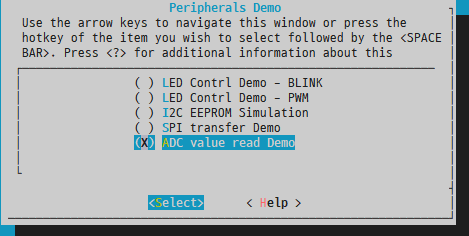
Example
- Use the "adc" command to read a channel for the required number of times. Try again after changing the input level.

Low Power Development Guide
Introduction
The Low Power Development Guide describes how to use the power management API to implement low power applications.
Low Power State
The device's internal power management unit (PMU) provides multiple power saving modes. However, not all PMU modes are suitable for actual use cases. Instead, it is recommended that users use the PM API provided in the SDK.
The SDK supports the following PM states:
- Active state
- Light Sleep mode
- Deep Sleep mode
- Hibernation mode
In the active state, each component of the SoC remains powered and operational. Conversely, hibernation mode is the most energy-efficient, with most components powered off, except for those in the Always-On (AON) power domain.
State Transition
After enabling power management in the SDK, the device automatically transitions between different power consumption modes to optimize power consumption.
Each power consumption mode requires specific save and/or restore operations to ensure consistency in context before and after entering a low-power state. More energy-efficient states involve more extensive operations and therefore require more time.
The device's next power consumption mode is determined by its idle cycle, which is the time interval until the next scheduled task. The time conditions for each PM state are shown below, but can be adjusted according to application requirements.
| Power Mode | Expected Idle Cycle |
|---|---|
| Active Mode | - |
| Light Sleep Mode | > 550 microseconds |
| Deep Sleep Mode | > 10.2 milliseconds |
| Hibernation Mode | > 1.7 seconds |
When the device switches to a power consumption mode (other than active mode), it will always return to active mode after a wake-up event occurs. Direct conversion between two different power consumption modes is not supported.
Conversion diagram:

Power Management Conditions
Typically, transitioning to a low-power state depends on the following factors:
- The operating system has sufficient idle time, meaning all threads are idle and waiting for events.
- The peripheral drivers have not disabled power management.
- The user applications have enabled power management and specific power management states.
Network Keepalive
Maintain network connectivity in all low-power states.
In deep sleep mode and hibernation mode, a dedicated software operation is used to monitor Wi-Fi activity and trigger wake-up events when necessary. This software runs from RAM, eliminating the need for flash and other high-power components. This approach ensures Wi-Fi connectivity while minimizing the device's overall power consumption.
Wake-Up Source
When the device is in a low-power state, the following peripherals can be used as wake-up sources:
- RTC
- GPIO
- UART
- SDIO
- USB
The wake-up events are not always available and depend on the specific power management state. The RTC and GPIO can be used to wake up the device in all low-power states.
For detailed information on using UART, SDIO, and USB for wake-up, please consult Telink for support.
RTC
The RTC (Real-Time Clock) can be set to prompt the device to wake up at a specified future time. This configuration is typically managed by the operating system to ensure that operating system threads operate at the correct intervals.
Users don't need in-depth knowledge of PM operations to leverage this. They can use standard operating system APIs, such as delay functions or inter-process communication functions. In the background, the operating system collects thread-related data, adjusts the RTC to the nearest required wake-up time, and transitions to a low-power state when all threads are idle.
It is recommended to avoid direct access to the RTC API while power management is active.
GPIO
The GPIO (General Purpose Input/Output) can trigger wake-up events in all power management states.
To designate a GPIO as a wake-up source, its pin should be set to input mode, and the corresponding interrupt should be activated. Configuring pull-up or pull-down settings is also beneficial. Subsequently, the application must notify the power management module to recognize it as a wake-up source.
It should be emphasized that only GPIOs in the AON (Always On) domain have the capability for wake-up functions. Specifically, these GPIOs range from GPIO0 to GPIO7.
Power Management States
Active State
In this state, the SoC (System on Chip) is fully operational. All peripherals are powered on and ready for use.
Light Sleep Mode
In Light Sleep Mode:
- The processor and peripherals are controlled by clock-gates.
- All register contents and memory are retained.
- Timer counts remain unchanged.
Software responsibilities include:
- Saving the system time when entering this state.
- Restoring the system time upon exit, taking into account the time spent in this state.
Deep Sleep Mode
In Deep Sleep Mode:
- The processor and peripherals are controlled by power-gates.
- The XTAL (crystal oscillator) and PLL (phase-locked loop) are turned off.
- The processor and peripheral registers are not retained.
Software responsibilities include:
- Saving the system time and suspending peripheral devices when entering this state.
- Restoring the system time and resuming peripheral devices when exiting this state.
Hibernation Mode
During hibernation mode:
- The processor, peripherals, XTAL, and PLL are all controlled by power-gates.
- Additional processor LDOs (low-dropout regulators) and DC-DC (DC-to-DC converters) are disabled.
- All memory sections, except for portions in the AON (always-on) SRAM, are powered down.
Software tasks include:
- Saving the system time, suspending peripheral devices, and storing memory contents to flash when entering hibernation mode.
- When leaving this low power state, restoring the system time, resuming peripheral devices, and retrieving memory contents from flash upon waking up.
The Deep Sleep Mode has a limitation. Considering that certain context is stored in flash, the erase and write cycles of flash are limited. Considering the characteristics of the SoC's integrated flash, it is recommended to limit the occurrence of hibernation mode to a maximum of 27 times per day.
API Interfaces
Prerequisites
To enable power management, users should configure the PM options from menuconfig.

To use the PM API interface, users should also enable the PM API options in menuconfig.

The following APIs can be used to customize the behavior of the power management module:
- tlsr_pm_power_down
- tlsr_pm_enable_wakeup_io
- tlsr_pm_disable_wakeup_io
- tlsr_pm_enable_lowpower
- tlsr_pm_disable_lowpower
- tlsr_pm_disable_lowpower_timeout
- tlsr_pm_enable_state
- tlsr_pm_disable_state
- tlsr_pm_register_handler
- tlsr_pm_unregister_handler
Power Down (with Duration)
Function:
int tlsr_pm_power_down(uint32_t duration)
The tlsr_pm_power_down function can be used to unconditionally put the device into hibernation mode. All network connections will be lost.
If duration is set to a non-zero value, the device will wake up after the specified time. A zero duration means that only GPIO events can wake up the device. After waking up, the device initializes as if undergoing a power-on reset.
GPIO Wakeup Control
Functions:
int tlsr_pm_enable_wakeup_io(uint8_t pin)
int tlsr_pm_disable_wakeup_io(uint8_t pin)
There are a total of 8 GPIOs (from GPIO0 to GPIO7) in the AON domain. Each GPIO can be designated as a wake-up pin. However, if tlsr_pm_enable_wakeup is not called, even if the GPIO is set to input, a wake-up event will not be started.
Low-Power Control
Functions:
int tlsr_pm_enable_lowpower(void)
int tlsr_pm_disable_lowpower(void)
These functions allow the application to control PM operations. If the application needs to temporarily disable PM for a critical task, it should call tlsr_pm_disable_lowpower. When the task is complete and PM needs to be reactivated, tlsr_pm_enable_lowpower should be called.
Low Power State Control
Functions:
int tlsr_pm_enable_state(enum telink_pm_state state)
int tlsr_pm_disable_state(enum telink_pm_state state)
Since different PM states are supported, the application can enable or disable each specific PM state. When a specific state is disabled, the device will transit to the next available PM state during idle periods.
If all states are disabled, the device will not enter any low-power states.
Power Management State Change Notification
Prototype:
typedef void (*tlsr_pm_notify)(enum telink_pm_state state);
Functions:
int tlsr_pm_register_handler(telink_pm_notify callback)
int tlsr_pm_unregister_handler(telink_pm_notify callback)
The application can receive notifications of PM state changes. It should call tlsr_pm_register_handler to register the application-specific function to be called.
Multiple callbacks can be registered by calling tlsr_pm_register_handler multiple times with different callbacks.
When entering a low-power state, the callback will be called, with the state parameter being one of TLSR_PM_STATE_LIGHT_SLEEP, TLSR_PM_STATE_DEEP_SLEEP, or TLSR_PM_STATE_HIBERNATION.
When waking up from a low-power state, the callback will be called, with the state parameter always being TLSR_PM_STATE_ACTIVE.
For example, these callback functions can be used to perform application-specific cleanup operations before entering a low-power state, such as turning off LEDs or disabling sensors.
Note
- These callback functions are called from the operating system's idle task, so the size of the application code is limited by the stack size of the idle task. Additionally, all interrupts are disabled. The callback function should not call any operating system APIs or interrupt-related functions. It is recommended that the function complete as quickly as possible.
SDK Power Management Example
Introduction
Example
The SDK Power Management Example describes how to build and run the power management provided by the SDK. This example is intended to test various configurations and features of the PM (Power Management) function.
For more information, refer to the following sections:
-
SDK Getting Started Guide, for setting up the build environment.
-
SDK Example Peripheral, for building the example.
-
Low Power Development Guide, for power management.
-
Wi-Fi Software Development Guide, for Wi-Fi.
Power Management Command Line
The SDK provides CLI commands to configure and connect to Wi-Fi networks, as well as monitor status and statistics.
Before explaining the example, it is helpful to demonstrate how to use the CLI. The next section will show how the same procedure can be done automatically by the source code.
Build and Configuration
Follow these steps to build the example application:
$ make tlsr9xxxs_defconfig
$ make
After the build is successfully completed, wits.mcuboot.bin will be generated and can be loaded onto the development board.
Commands
In the console, use the following commands to connect to the Wi-Fi network. Users need to configure parameters based on their Wi-Fi AP environment:
(1) Register event callback to receive event:
$ wifi reg_evt_cb
(2) Start station mode:
$ wifi sta_start
(3) Configure station parameters, authentication type, SSID, and key:
$ wifi sta_cfg Redmi_Test 2 12345678 00:00:00:00:00:00 1 0
(4) Connect to the AP:
$ wifi sta_connect
Attempt to use wifi help to obtain available options and command descriptions.

By default, PM (power management) is disabled. You can enable it using the following commands:
(1) Enable Wi-Fi power-saving mode:
$ wifi sta_set_ps 1
(2) Register PM event callback:
$ pm reg_cb
(3) Enable global PM:
$ pm enable

Try using pm to get available options and command descriptions.
Power Management Example
The previous section demonstrated how to control the device using the CLI. In this section, an example shows how to achieve the same function using source code.
Build and Configuration
Follow these steps to build the low-power example application:
$ make tlsr9xxxs_defconfig
$ make menuconfig
  select Applications -> Power Save Demo
$ make

Before building the firmware, the AP information must be changed according to the test environment. The SSID, authentication type, and key should match the information of the AP to be connected to.
Source Code Modifications
Modify the source code according to the following configuration:

After successful build completion, the wits.mcuboot.bin file will be generated and can be loaded onto the development board.
Example
After startup, use the following command to connect to Wi-Fi and enable low-power mode:
$ lowpower 1
The device will attempt to connect to the Wi-Fi network and enter low-power mode. By default, the example configures the listening interval to 1000 milliseconds.

Device Firmware Update Guide
Introduction
The TLSR9118 SDK supports Device Firmware Updates Over The Air (DFU OTA). This guide provides detailed instructions on how to perform firmware updates using a network connection.
Within the SDK, we have integrated the widely-used open-source bootloader MCUBoot. Additionally, we provide a porting layer specifically tailored for certain architectures to facilitate seamless integration.
It is important to note that MCUBoot is designed to support full firmware updates and does not support incremental updates. For a more comprehensive understanding of MCUBoot and its functions, users are advised to consult its official documentation at: https://docs.mcuboot.com/.
The MCUBoot offers multiple configuration options to meet the needs of different applications. Some of these options can be accessed and modified via menuconfig, while others require manual adjustment in the mcboot_config.h file.
Work Flow
Advanced Operations
The process of updating device firmware can be summarised in the following steps:
-
Initial setup: The device is preloaded with the bootloader and primary application.
-
Boot process: At startup, the bootloader initiates the program located in the primary application partition.
-
Update preparation: Within the primary application, the update agent is responsible for downloading the new application firmware. This new firmware is stored in an secondary application partition.
-
Firmware download complete: Once the new application firmware is successfully downloaded, the application records this status and triggers a system reboot.
-
Bootloader check: During subsequent boot processes, the bootloader checks the recorded status. If updated firmware is detected in the secondary application partition, the bootloader exchanges firmware in the primary application partition.
-
Application startup: The bootloader then starts the application from the primary application partition, which now contains the updated firmware.
-
Status clearance: If the new application firmware is functioning normally, the application can proceed to clear the update status, indicating a successful update.

For the OTA firmware update process, the device must allocate the same size of space for the secondary application partition as the primary application partition. Additionally, a designated temporary zone is required as a temporary space for exchanging firmware between the primary application partition and the secondary application partition during the update process.
Flash Memory Layout
To successfully update the firmware, the device must designate specific regions in the flash memory. These regions include:
- Bootloader
- Primary Application Partition
- Secondary application partition
- Temporary zone
The following is the recommended layout for the internal 16Mbit flash memory of the TLSR9118:
| Component | Address | Size (KB) |
|---|---|---|
| Bootloader | 0x80000000 | 64 |
| Temporary zone | 0x80010000 | 16 |
| Storage file system | 0x80014000 | 16 |
| Hibernation backup | 0x80018000 | 416 |
| Primary application partition | 0x80080000 | 768 |
| Secondary application partition | 0x80140000 | 768 |
You can use the menuconfig process to modify the addresses and sizes of the flash layout. Any changes made to the flash layout must be followed by a rebuild of the bootloader and application to recognise these modifications.


Additionally, due to the size of flash erase blocks, addresses must be aligned to 4KB boundaries.
Firmware Building
Configuration and Build
The default configuration in the SDK has already enabled the firmware update function. Therefore, the generated application firmware will include the MCUBoot header, making it suitable for updates.
The following is an example of the menuconfig options to enable the firmware update function:

When device firmware updates are enabled, the typical output is named wits.mcuboot.bin.
Firmware Format
The MCUboot requires a mirror header that provides details about the firmware. A fixed-size header is always appended to the front of the executable firmware, and if additional information is needed, variable-sized TLV-formatted data is appended. During the build process, the imgtool tool appends this additional data.
The header includes the following details:
- Magic number
- Load memory address
- Header size
- TLV size
- Firmware size
- Flag bits
- Version
The trailer may include the following information:
- Public key or key hash
- Firmware hash
- Signature
Source Code Overview
Main MCUboot Source Files
The following are some important MCUBoot source code files.
| Source code | Description |
|---|---|
| lib/tlsr_mcuboot/mcuboot | Original MCUboot library code |
| lib/tlsr_mcuboot/mcuboot/wits | Telink porting layer for the SDK |
| lib/tlsr_mcuboot/loader | MCUboot bootloader main function |
| lib/tlsr_mcuboot/update_agent | MCUboot update agent example |
API Functions
The following functions are essential for both the bootloader and the application:
| Name | Description |
|---|---|
| boot_go | The bootloader calls it to initiate the application boot process. The process will include verification, exchange, and boot based on the status data. |
| boot_set_pending_multi | The application calls it to mark the image as pending, so that the bootloader can exchange and boot the image during the next reboot. |
| boot_set_confirmed_multi | The application calls it to mark the current image as valid and permanently set. |
| flash_area_open | Retrieve the flash area from the flash map based on the given identifier. |
| flash_area_read | Read the flash content into a buffer. |
| flash_area_write | Write the buffer to flash. |
| flash_area_close | Complete the flash operation |
Firmware Update Example
The device firmware can be updated using specific test commands. For example, our example update agent uses the HTTP protocol for firmware download. However, it is worth noting that other protocols can also be used for this purpose. During the update, the application must call the appropriate flash API functions to erase and write the updated firmware to the secondary partition.
Setting HTTP Server
This section outlines the setup process in a local area network (LAN) environment. Here, a wireless router acts as the gateway. Additionally, we will delve into the steps for deploying an HTTP server that will store the device firmware. The process of connecting the TLSR9118 to this wireless router via Wi-Fi is detailed in the "TLSR9118 WiFi Software Development Guide".

File Transfer
The following figure shows the beginning of the image update process. The new image is placed on the HTTP server with the IP address 192.168.1.133.
# mcuboot_agent http://192.168.1.133/wits.mcuboot.bin

After successful transmission, the device will automatically reboot. Subsequently, the bootloader will exchange the primary and secondary firmware, as shown in the figure below.

After the exchange is complete, the bootloader will start the new application.
Verify Firmware
To designate the new firmware as permanent, use the following command:
# mcuboot_confirm

Important Note: If this confirmation step is skipped, the bootloader will restore the firmware in the primary and secondary partitions during the next device reboot, effectively reverting to the previous firmware. This is a safety measure in case the updated firmware encounters execution issues.
Secure Boot (TBD)
When Secure Boot is enabled, the device will only boot firmware signed with the user's secure key. The Secure Boot process consists of two steps:
(1) BootROM verifies the bootloader (2) The bootloader, in turn, verifies the application.
Secure Boot of BootROM
If the corresponding eFuse bit is set, the BootROM will enable Secure Boot. It uses the eFuse security key to verify the signature of the bootloader or the firmware located at the beginning of the flash memory. This firmware should have a Telink-specific header and the necessary details.
Secure Boot of the Bootloader
If the bootloader is built with the relevant menu options enabled, secure boot is enabled. During the boot process, the bootloader built with the secure key verifies the signature of the application firmware. This application should have an MCUBoot-specific header and TLVs with the necessary details.
Flash Encryption (TBD)
When flash encryption is enabled, the update process undergoes minor modifications. Considering that the original firmware data (unencrypted) should not be exposed, the firmware used for the update should also be encrypted before the download stage.
The build system supports flash encryption. After enabling, it generates encrypted firmware and original firmware.
Flash Command Line Tool
Introduction
The command line interface (CLI) is used to program devices and can be executed on different operating systems. To adapt to various situations, it requires parameters for configuration or the use of configuration files.
To enable CLI communication, the device must be set to "Boot from UART". The device supports different boot modes.
| Boot Mode | GPIO3 | GPIO2 |
|---|---|---|
| Boot From Flash | 1 | 0 |
| Boot From UART | 0 | 1 |
| Boot From USB | 1 | 0 |
| Boot From SDIO | 0 | 0 |
If the device supports hardware reset, the CLI tool will automatically select the boot mode and reset the device.
In the following content, the CLI is commonly referred to as "sctool". The sctool primarily consists of two parts:
-
Optional: This part refers to parameters used to configure or modify the behavior of the entire process.
-
Operations: This part includes the execution section, which performs the following tasks:
- Information query
- Flash operations
- eFuse operations
The entire process can be divided into four stages.
CLI
Execute command: sctool
usage: sctool [-h] [-v VERBOSE] [-V] [-p PORT] [-da DA] [-b BAUDRATE]
[--before {hw_reset,no_reset}] [--manual]
[--after {hw_reset,sw_reset,no_reset}] [-c CONFIG]
{test_write,test_read,hw_reset,sw_reset,list_ports,chip_id,da_ver,upload_da,flash_read,fl
ash_write,flash_erase,flash_size,flash_chip_erase,efuse_read,efuse_write,efuse_read_bi
n,efuse_write_bin,efuse_size}
Option Guide
-
-h: Print help information
-
-v: Detailed level of output information
- 0 - Display critical messages only.
- 1 - Display critical and informational messages (default).
- 2 - Display all messages.
-
-p: Serial port number for communication with the device
-
-da: The DA image path.
-
-b: New baud rate for communication after uploading DA.
-
--before: Actions in the before stage.
- hw_reset (default)
- no_reset
-
--after: Actions in the after stage.
- hw_reset
- sw_reset
- no_reset (default)
-
--manual: Execute the operation only.
-
-c: Configuration file path.
To satisfy basic command requirements, the command should include both the port number and DA. The following is an example command for reading "da_ver":
For Windows system - read da_ver
sctool.exe -p COM3 -b 2000000 -da da/da.ram.bin da_ver
For Ubuntu 18.04 system - read da_ver
./sctool -p /dev/ttyUSB0 -b 2000000 -da da/da.ram.bin da_ver
The following example uses Windows as a template. For the Ubuntu version, replace "sctool.exe" to "./sctool" and replace "COMX" to "/dev/ttyUSBX".
Configuration file
To simplify commands and reduce the number of parameters required for operations, using a configuration file is more convenient. The configuration file should be in INI format, with a structure similar to the following:
[Settings]
verbose = 1
port = COM3
agent = da/da.ram.bin
baudrate = 2000000
before = hw_reset
after = no_reset
In the command line, use the configuration file by passing the "-c" parameter.
For Windows system - read "da_ver"
sctool.exe -c config.ini da_ver
The configuration file can be used as the default value, and options to override it can be provided when necessary.
For Windows system - read "da_ver" using COM0.
sctool.exe -c config.ini da_ver -p COM0
For Windows system - read "da_ver" using COM0 and baud rate 115200.
sctool.exe -c config.ini da_ver -p COM0 -b 115200
Operation Instruction
This operation requires certain parameters and can add additional optional parameters, such as "--verify". To provide a simplified example, the following template assumes you are using a Windows system. If you are using Ubuntu, replace "sctool.exe" to "./sctool" accordingly.
Test
test_write <SIZE>, write a specific size to test communication.
sctool.exe -c config.ini test_write 512
test_read <SIZE>, read a specific size to test communication.
sctool.exe -c config.ini test_read 512
General Operations
chip_id, read the device's chip ID
sctool.exe -c config.ini chip_id
da_ver, read the da version
sctool.exe -c config.ini da_ver
upload_da, upload da
sctool.exe -c config.ini upload_da
Reset operations
hw_reset, perform a hardware reset (this function requires hardware support)
sctool.exe -c config.ini hw_reset
sw_reset, perform a software reset (the device must load DA)
sctool.exe -c config.ini upload_da
sctool.exe -c config.ini sw_reset
Other Operations
list_ports, list available ports for UART (this method does not require config.ini)
sctool.exe list_ports
Flash Operations
flash_read <ADDR> <SIZE> <FILENAME>
Read flash from <ADDR> with a size of <SIZE> and save it to <FILENAME>.
Due to the flash mapping method, the starting address of flash is "0x80000000" (0x80000000 means the 0x00000000 on the flash addresses).
sctool.exe -c config.ini flash_read 0x80000000 0x2000 boot.bin
flash_write <ADDR> <FILENAME> [--verify]
Start writing flash from <ADDR>, with data content from <FILENAME>.
Due to the flash mapping method, the starting address of the flash is "0x80000000". (0x80000000 means the 0x00000000 on the flash addresses.)
sctool.exe -c config.ini flash_write 0x80000000 boot.bin
--verify: After writing the data, read it back and verify it using <FILENAME>.
sctool.exe -c config.ini flash_write 0x80000000 boot.bin --verify
Note
- The flash_write automatically performs an erase operation, with erase blocks aligned to 4 KB.
flash_erase <ADDR> <SIZE>
Erase the flash starting from <ADDR> with a size of <SIZE>.
sctool.exe -c config.ini flash_erase 0x80000000 0x2000
Note
- Please note that the erase operation requires the size (<SIZE>) to be aligned with 4 KB. This means the actual size should be increased by 0x1000.
flash_size, obtain the flash size (Bytes).
sctool.exe -c config.ini flash_size
flash_chip_erase, perform chip erase.
sctool.exe -c config.ini flash_chip_erase
eFuse Operations
efuse_read <START_BIT> <BIT_WIDTH>
Read eFuse data from <START_BIT> with a bit width of <BIT_WIDTH>.
sctool.exe -c config.ini efuse_read 0 8
efuse_write <START_BIT> <BIT_WIDTH> <HEX_DATA>
Writes eFuse data starting from <START_BIT>, with a bit width of <BIT_WIDTH> and data of <HEX_DATA>.
sctool.exe -c config.ini efuse_write 0 64 0x0123456789ABCDEF
Note
- Using the efuse_write function will permanently change the behavior of the eFuse. The efuse_write can only change data from "0" to "1".
efuse_read_bin
Read the entire eFuse and save it to <FILENAME>.
sctool.exe -c config.ini efuse_read_bin efuse.bin
efuse_write_bin <FILENAME> [--verify]
Write the entire eFuse data using the content from <FILENAME>.
sctool.exe -c config.ini efuse_write_bin efuse.bin
--verify: After writing the eFuse data, read it back and verify it using <FILENAME>.
sctool.exe -c config.ini efuse_write_bin efuse.bin --verify
Note
- efuse_write_bin can only change data from "0" to "1".
efuse_size, obtain the eFuse size (bits)
sctool.exe -c config.ini efuse_size
Example
Flash Operations
XIP Boot
sctool.exe -c config.ini --after hw_reset flash_write 0x80000000 image/nuttx.tlsrboot.xip.bin
Nuttx Boot
sctool.exe -c config.ini --after hw_reset flash_write 0x80040000 image/nuttx.mcuboot.xip.bin
Wits
sctool.exe -c config.ini --after hw_reset flash_write 0x80140000 image/wits.bin
Manual Flash for multi-sector
sctool.exe -c config.ini --before=hw_reset --after=no_reset upload_da
sctool.exe -c config.ini --manual flash_write 0x80000000 image/nuttx.tlsrboot.xip.bin
sctool.exe -c config.ini --manual flash_write 0x80040000 image/nuttx.mcuboot.xip.bin
sctool.exe -c config.ini --manual flash_write 0x80140000 image/wits.bin
sctool.exe -c config.ini hw_reset
For Devices that do not Support the Secure Recovery Mechanism
If your device does not support the secure recovery mechanism, you will need to follow a series of steps to enter "boot from UART" mode and perform programming. In this chapter, you will find detailed instructions on how to troubleshoot such devices and successfully initialize the UART communication boot process. Please follow the steps below to ensure a smooth and efficient programming process.
-
Step 1: Switch SW2 to "0100" to enable "Boot via UART".
-
Step 2: Power on the target device.
-
Step 3: Execute the CLI operation, which will wait for the device to enter UART mode. For example: sctool.exe -c config.ini flash_read 0x80000000 0x2000 boot.bin
-
Step 4: Trigger the SW3 button for a hardware reset to enter UART mode and wait for the command to complete.
-
Step 5: Restore SW2 to "Boot from Flash", then trigger SW3 for a reboot.
Frequently Asked Questions
Q: Error message: "Error: Could not open serial port COMn" on Windows or "Error: Could not open serial port /dev/usbttyn" on Linux
A: It seems the operating system has not detected the COM port. You can enter the following command to check available COM ports and select one.
sctool.exe list_ports
Available Ports:
COM1
COM4
Q: Error message: "Error: Serial Port Read Timeout!"
A: The COM port has been detected, but communication has failed. Please check if you have switched the EVB/EVK to "Boot via UART" mode. After setting "Boot via UART" mode and triggering the reset button, you will see "0x00000000 CCC..." on the terminal.
Q: Why is it necessary to immediately click the reset button after entering the 'sctool.exe xxx' command?
A: The Flash tool requires a compatible DA image on the target device to process the relevant commands. The "Boot via UART" mode allows sctool.exe to upload the DA. If the device is not in "Boot via UART" mode, the command will be checked once per second until it waits for 10 seconds. This is why we need to click the reset button within 10 seconds to enter "Boot via UART" mode and let sctool.exe to complete its command.
Q: On a Linux computer, how to confirm which port is used for flashing the image, either /dev/ttyUSB0 or /dev/ttyUSB1?
A: In Linux, it will set the first USB-UART as /dev/ttyUSB0 and the second as /dev/ttyUSB1.
To determine which port is being used for flashing the image, you can use minicom to check which of them continuously outputs "CCC..." in "Boot via UART" mode. Below is the example.

Single Board Smoke Testing Guide
Overview
Smoke Testing
The smoke testing is an initial test in the software development process, primarily used for quick basic function verification of software version packages rather than in-depth testing. Before performing detailed testing, the smoke testing should be performed first, with the primary purpose of quickly checking whether the software's basic functions have defects. The smoke testing primarily includes Ping testing and Iperf testing.
Ping Testing
Ping is a network testing tool primarily used to detect network connection quality. It determines network connection stability by sending ICMP response request messages to a specified network host and waiting for its response.
Iperf Testing
IPerf is a network performance testing tool that can measure the maximum bandwidth performance of TCP and UDP. It can test TCP or UDP traffic from one end to the other and provide information related to network bandwidth, latency, jitter, and data packet loss.
Smoke Testing Software Compilation
Software Compilation Process
To perform single-board smoke testing, first you need to compile the corresponding software. Please follow the steps below:
Step 1: Select the corresponding config, which is tlsr9118s_defconfig
$ cd wits-sdk
$ make distclean
$ make tlsr9118s_defconfig
Step 2: Enable testing function
$ make menuconfig
(1) Enter the SDK

(2) Check Include Wi-Fi CLIs for API testing, and enter Wi-Fi CLI

(3) Select to enable the necessary functions: STA, SCAN, SAP

Step 3: Compile
$ make
Step 4: Verify that the wits.mcuboot.bin file has been generated in the wits-sdk path.
Wi-Fi STA Single Board Smoke Test
Overview
Any device connected to a wireless AP can be referred to as a station (STA: Station). In the STA mode smoke test, it primarily implements the connection with the AP device and performs data communication.
Test Process
Using the Wi-Fi help command, the following command list can be displayed:

Step 1: Reset the single board

Step 2: Start STA

Step 3: Scan the network

Step 4: View the scan results

Step 5: Configure the network connection information

Step 6: Connect to the network

Step 7: Start the DHCP Client

Step 8: View STA network information

Step 9: Ping test

Step 10: Iperf Test

Wi-Fi AP Single Board Smoke Test
Overview
A Wireless Access Point (AP) is a critical device in a wireless network. As a network interface, an AP enables wireless devices to connect. It can also serve as a generic term for devices such as wireless routers, wireless gateways, and wireless bridges. In this AP mode smoke test, a single board is primarily implemented as an AP device to communicate with STA devices.
Test Process
Using the Wi-Fi help command, the following command list can be displayed:
Step 1: Reset the Single Board
Step 2: Set AP

Step 3: Start AP
Step 4: Set IP address

Step 5: Start DHCP server

Step 6: View AP configuration information

Step 7: STA connects to AP

Step 8: View STA information
Step 9: AP ping STA

Step 10: Iperf test

CMSIS-FreeRTOS API Guide
Introduction
The TLSR9118 SDK integrates CMSIS-FreeRTOS as an API, enabling users to utilise various operating system functions in their applications. While native FreeRTOS data types and functions remain available, it is strongly recommended to use the CMSIS-FreeRTOS API at the application layer.
Overview
The TLSR9118 SDK uses the CMSIS-FreeRTOS interface:
-
Header file
- include/cmsis_os.h
-
Definition
- include/hal/cmsis_os2.h
Applications should reference <include/cmsis_os.h> rather than <include/hal/cmsis_os2.h>.
Build
No special settings are required to enable the CMSIS-FreeRTOS API, as it is always enabled by default.
References
The CMSIS-FreeRTOS in the TLSR9118 SDK is based on the CMSIS-RTOS API v2 API and is divided into the following categories:
-
Kernel information and control
-
Thread management
-
Thread flags
-
Event flags
-
General wait functions
-
Timer management
-
Mutex management
-
Semaphores
-
Memory pool (currently not supported)
-
Message queues
These categories will be detailed below.
Kernel Information and Control
The kernel information and control functions group allow the following operations:
-
Obtain information about the system and lower layer kernel.
-
Obtain version information for the CMSIS-RTOS API.
-
Initialize the RTOS kernel to create objects.
-
Start the RTOS kernel and thread switching.
-
Check the execution status of the RTOS kernel.
The kernel information and control functions cannot be called from interrupt service routine (ISR).
Data Structure
- struct osVersion_t
It identifies the lower layer RTOS kernel and API version number.
The versions are represented in a combined decimal format: major version number . minor version number . revision number: mmnnnrrrr
| Data Field | - | Version |
|---|---|---|
| uint32_t | api | API version (major version number.minor version number.revision number: mmnnnrrrr decimal). |
| uint32_t | kernel | Kernel version (major version number.minor version number.revision number: mmnnnrrrr decimal). |
Use osKernelGetInfo to retrieve the version number.
Enumeration Type
- Enum osKernelState_t
The kernel state retrieved via osKernelGetState.
If osKernelGetState fails or is called in an ISR, it will return osKernelError; otherwise, it will return the kernel state.
| Enumerator | State |
|---|---|
| osKernelInactive | Inactive. The kernel is not yet ready. osKernelInitialize needs to be successfully executed. |
| osKernelReady | Ready. The kernel is not yet running. osKernelStart transfers the kernel to the running state. |
| osKernelRunning | Running. The kernel has been initialized and is running. |
| osKernelLocked | Locked. The kernel has been locked using osKernelLock. The functions osKernelUnlock or osKernelRestoreLock unlock it. |
| osKernelSuspended | Suspended. The kernel is suspended using osKernelSuspend. The function osKernelResume returns normal operation. |
| osKernelError | Error. An error has occurred. |
| osKernelReserved | Prevent enumeration downgrade compiler optimisation. Reserved. |
Functions
osStatus_t osKernelInitialize(void)
The function osKernelInitialize initializes the RTOS kernel.
Before successful execution, only the functions osKernelGetInfo and osKernelGetState can be called.
| Return value | Description |
|---|---|
| osOK | When successful. |
| osError | When an unspecified error occurs. |
| osErrorISR | If called from ISR. |
| osErrorNoMemory | If memory cannot be reserved for the operation. |
osStatus_t osKernelGetInfo(osVersion_t *version, char *id_buf, uint32_t *id_size)
The osKernelGetInfo function retrieves the API and kernel version of the lower layer RTOS kernel, as well as a human-readable identifier string for the kernel. It can be safely called before initializing or starting the RTOS (calling osKernelInitialize or osKernelStart).
| Parameter | Type | Description |
|---|---|---|
| version | Output parameter | Pointer to buffer used to retrieve version information. |
| id_buf | Output parameter | Pointer to buffer used to retrieve kernel identifier string. |
| id_size | Input parameter | Buffer size for the kernel identifier string. |
| Return value | Description |
|---|---|
| osOK | When successful. |
| osError | When an unspecified error occurs. |
| osErrorISR | If called from ISR. |
osKernelState_t osKernelGetState(void)
The function osKernelGetState returns the current state of the kernel and can be safely called before initializing or starting the RTOS (calling osKernelInitialize or osKernelStart). If it fails, it will return osKernelError; otherwise, it will return the kernel state (see osKernelState_t for a list of kernel states).
| Return Value | Description |
|---|---|
| osKernelError | If called from ISR. |
| Actual kernel state | Other scenarios. |
osStatus_t osKernelStart(void)
The function osKernelStart starts the RTOS kernel and begins thread switching. In the event of success, it does not return to its calling function. Before successful execution, only the functions osKernelGetInfo, osKernelGetState, and object creation functions (osXxxNew) can be called.
At least one initial thread must be created before calling osKernelStart; see osThreadNew.
| Return value | Description |
|---|---|
| osOK | When successful. |
| osError | When an unspecified error occurs. |
| osErrorISR | If called from ISR. |
int32_t osKernelLock(void)
The function osKernelLock allows locking all task switches. It returns the previous value of the lock status (1 if locked, 0 if unlocked), or otherwise returns a negative number representing an error code (see osStatus_t).
| Return value | Description |
|---|---|
| osError | When an unspecified error occurs. |
| osErrorISR | If called from ISR. |
| Previous value in locked state | Other scenarios. |
int32_t osKernelUnlock(void)
The function osKernelUnlock restores from osKernelLock. It returns the previous value of the lock state (1 if locked, 0 if unlocked), or otherwise returns a negative number representing an error code (see osStatus_t).
| Return value | Description |
|---|---|
| osError | When an unspecified error occurs. |
| osErrorISR | If called from ISR. |
| Previous value in locked state | Other scenarios. |
int32_t osKernelRestoreLock(int32_t lock)
The function osKernelRestoreLock restores the previous lock state after osKernelLock or osKernelUnlock. The parameter lock specifies the lock state obtained by osKernelLock or osKernelUnlock.
The function returns the new value of the lock state (1 if locked, 0 if unlocked), or otherwise returns a negative number indicating an error code (see osStatus_t).
| Return value | Description |
|---|---|
| osError | When an unspecified error occurs. |
| osErrorISR | If called from ISR. |
| New lock state | Other scenarios. |
uint32_t osKernelSuspend(void)
Not supported.
uint32_t osKernelResume(void)
Not supported.
uint32_t osKernelGetTickCount(void)
The function osKernelGetTickCount returns the tick count of the current RTOS kernel.
uint32_t osKernelGetTickFreq(void)
The function osKernelGetTickFreq returns the frequency of the current RTOS kernel tick.
uint32_t osKernelGetSysTimerCount(void)
The function osKernelGetSysTimerCount returns the current value of the RTOS kernel system timer, which is a 32-bit value. This value is a rolling 32-bit counter composed of the kernel system interrupt timer value and the counter that counts these interrupts (RTOS kernel tick).
This function allows the implementation of very short timeout checks that are lower than the RTOS tick granularity. Such checks may be required when checking for busy states during device or peripheral initialization routines.
uint32_t osKernelGetSysTimerFreq(void)
The function osKernelGetSysTimerFreq returns the frequency of the current RTOS kernel system timer.
Thread Management
The thread management function group allows the definition, creation, and control of thread functions in the system.
The threads can be in the following states:
-
RUNNING: The currently running thread is in the RUNNING state. Only one thread can be in this state at a time.
-
READY: A thread ready to run is in the READY state. Once a running thread terminates or is blocked, the next ready thread with the highest priority becomes the running thread.
-
BLOCKED: A thread that is delayed, waiting for an event to occur, or suspended is in the BLOCKED state.
-
TERMINATED: When osThreadTerminate is called, the thread is terminated, and resources have not yet been released (applies to attachable threads).
-
INACTIVE: A thread that has not been created or has been terminated and all resources have been released is in the INACTIVE state.
The thread state changes as follows:
-
A thread is created using the osThreadNew function. This places the thread in the ready or running state (depending on the thread priority).
-
CMSIS-RTOS is preemptive. The active thread with the highest priority becomes the running thread, provided it is not waiting for any events. The initial priority of a thread is defined by osThreadAttr_t, but it can be changed during execution using the osThreadSetPriority function.
-
A running thread transitions to the blocked state when it is delayed, waiting for an event, or suspended.
-
An active thread can be terminated at any time using the osThreadTerminate function. A thread can also be terminated by returning from the thread function. A terminated thread is in the inactive state and typically does not consume any dynamic memory resources.

Data Structure
- struct osThreadAttr_t
| Data Field | - | Description |
|---|---|---|
| const char * | name | The thread's name. A pointer to a constant string representing the thread object's readable name (displayed during debugging). Default value: NULL, no name specified (the debugger may display the function name). |
| uint32_t | attr_bits | Attribute bits. Options can be set using the following bit masks: osThreadDetached: Create the thread in detached mode (default); osThreadJoinable: Create the thread in joinable mode. |
| void * | cb_mem | Control block memory. A pointer to the memory location of the thread control block object. Default value: NULL, uses automatic dynamic allocation for thread control block memory. |
| uint32_t | cb_size | Size of the control block memory provided. The size of the memory block passed via cb_mem (in bytes). Default value: 0 indicates that the memory provided via cb_mem is not used. |
| void * | stack_mem | Stack memory. A pointer to the memory location of the thread stack (64-bit aligned). Default value: NULL, uses thread stack management to allocate the stack from a fixed-size memory pool. |
| uint32_t | stack_size | The size of the stack. The specified size of the stack (in bytes). Default value: 0 indicates that the memory provided by stack_mem is not used. |
| osPriority_t | priority | Initial thread priority (default: osPriorityNormal). Specifies the initial thread priority using the value of osPriority_t. Default value: osPriorityNormal. |
| TZ_ModuleId_t | tz_module | Module identifier. TrustZone thread context management identifier used to allocate context memory for threads. The RTOS kernel running in non-secure state calls the interface functions defined in the header file TZ_context.h. For threads that do not use secure calls at all, this can be safely set to zero. See TrustZone RTOS Context Management. Default value: 0 No thread context specified. |
| uint32_t | reserved | Reserved (must be 0). Reserved for future use. |
Type Definition
void (*osThreadFunc_t)(void *argument)
Thread entry function. Setting a new thread (osThreadNew) will begin execution by calling this entry function. Optional parameters can be used to pass arbitrary user data to the thread, that is, for thread identification or runtime parameters.
| Parameter | Type | Description |
|---|---|---|
| argument | Input parameter | Any user data set in osThreadNew. |
- osThreadId_t
Thread ID identifies the thread.
Returned by:
-
osThreadNew
-
osThreadGetId
-
osThreadEnumerate
-
osMutexGetOwner
Enumeration Type
- enum osThreadState_t
Thread state retrieved via osThreadGetState. If osThreadGetState fails or is called from an ISR, it will return osThreadError; otherwise, it will return the thread state.
| Enumerator | Description |
|---|---|
| osThreadInactive | Inactive. The thread has been created but is not actively used, or has been terminated (used for static control block allocation; returns osThreadError when using a memory pool because the control block is no longer valid) |
| osThreadReady | Ready. The thread is ready to execute but is not currently running. |
| osThreadRunning | Running. The thread is currently running. |
| osThreadBlocked | Blocked. The thread is currently blocked (delayed, waiting for an event, or suspended). |
| osThreadTerminated | Terminated. The thread has been terminated, and all resources have not yet been released (applies to connectable threads). |
| osThreadError | Error. The thread does not exist (causing an error condition) and cannot be scheduled. |
| osThreadReserved | Prevents enumeration downgrade compiler optimisation. |
- enum osPriority_t
The osPriority_t value specifies the priority of the thread. The default thread priority should be osPriorityNormal. If an active thread becomes ready and its priority is higher than the currently running thread, a thread switch will occur immediately. The system continues to execute the thread with the higher priority.
| Enumerator | Description |
|---|---|
| osPriorityNone | No priority (uninitialized). |
| osPriorityIdle | Reserved for idle threads. This lowest priority should not be used for any other threads. |
| osPriorityLow | Priority: Low. |
| osPriorityLow1 | Priority: Low + 1. |
| osPriorityLow2 | Priority: Low + 2. |
| osPriorityLow3 | Priority: Low + 3. |
| osPriorityLow4 | Priority: Low + 4. |
| osPriorityLow5 | Priority: Low + 5. |
| osPriorityLow6 | Priority: Low + 6. |
| osPriorityLow7 | Priority: Low + 7. |
| osPriorityNormal5 | Priority: Normal + 5. |
| osPriorityNormal6 | Priority: Normal + 6. |
| osPriorityNormal7 | Priority: Normal + 7. |
| osPriorityAboveNormal | Priority: Above Normal. |
| osPriorityAboveNormal1 | Priority: Above Normal + 1. |
| osPriorityAboveNormal2 | Priority: Above Normal + 2. |
| osPriorityAboveNormal3 | Priority: Above Normal + 3. |
| osPriorityAboveNormal4 | Priority: Above Normal + 4. |
| osPriorityAboveNormal5 | Priority: Above Normal + 5. |
| osPriorityAboveNormal6 | Priority: Above Normal + 6. |
| osPriorityAboveNormal7 | Priority: Above Normal + 7. |
| osPriorityHigh | Priority: High. |
| osPriorityHigh1 | Priority: High + 1. |
| osPriorityHigh2 | Priority: High + 2. |
| osPriorityHigh3 | Priority: High + 3. |
| osPriorityHigh4 | Priority: High + 4. |
| osPriorityHigh5 | Priority: High + 5. |
| osPriorityHigh6 | Priority: High + 6. |
| osPriorityHigh7 | Priority: High + 7. |
| osPriorityRealtime | Priority: Realtime. |
| osPriorityRealtime1 | Priority: Realtime + 1. |
| osPriorityRealtime2 | Priority: Realtime + 2. |
| osPriorityRealtime3 | Priority: Realtime + 3. |
| osPriorityRealtime4 | Priority: Realtime + 4. |
| osPriorityRealtime5 | Priority: Realtime + 5. |
| osPriorityRealtime6 | Priority: Realtime + 6. |
| osPriorityRealtime7 | Priority: Realtime + 7. |
| osPriorityISR | Reserved for ISR delay threads. This highest priority may be used by RTOS implementations but must not be used for any user threads. |
| osPriorityError | System cannot determine priority or priority is invalid. |
| osPriorityReserved | Prevents enumeration downgrade compiler optimisation. |
Functions
osThreadId_t osThreadNew(osThreadFunc_t func, void *argument,const osThreadAttr_t *attr)
The function osThreadNew starts a thread function by adding it to the active thread list and setting it to the READY state. The thread function's parameters are passed using the parameter pointer *argument. When the priority of the created thread function is higher than that of the current RUNNING thread, the created thread function starts immediately and becomes the new RUNNING thread. Thread attributes are defined using the parameter pointer attr. Attributes include thread priority, stack size, or memory allocation settings.
This function can be safely called before the RTOS starts (calling osKernelStart), but it cannot be called before initialization (calling osKernelInitialize).
The osThreadNew function returns a pointer to the thread object identifier. If an error occurs, it returns NULL.
| Parameter | Type | Description |
|---|---|---|
| func | Input parameter | Thread function. |
| argument | Input parameter | Pointer passed to the thread function as start parameter. |
| attr | Input parameter | Thread attributes; NULL: default value. |
| Return value | Description |
|---|---|
| thread ID | On success. |
| NULL | On error. |
const char *osThreadGetName(osThreadId_t thread_id)
The function osThreadGetName returns a pointer to the name string of the thread identified by the parameter thread_id. If an error occurs, it returns NULL.
| Parameter | Type | Description |
|---|---|---|
| thread_id | Input parameter | Thread ID obtained from osThreadNew or osThreadGetId. |
| Return value | Description |
|---|---|
| Thread name string ending with null | On success. |
| NULL | On error. |
osThreadId_t osThreadGetId(void)
The function osThreadGetId returns the thread object ID of the currently running thread. If an error occurs, it returns NULL.
| Return value | Description |
|---|---|
| thread ID | On success. |
| NULL | On error. |
osThreadState_t osThreadGetState(osThreadId_t thread_id)
The osThreadGetState function returns the state of the thread identified by the thread_id parameter. If it fails or is called from an ISR, it returns osThreadError; otherwise, it returns the thread state (see osThreadState_t for getting a list of thread states).
| Parameter | Type | Description |
|---|---|---|
| thread_id | Input parameter | Thread ID obtained from osThreadNew or osThreadGetId. |
| Return value | Description |
|---|---|
| Current thread state | On success. |
| osTheadError | On error. |
osStatus_t osThreadSetPriority(osThreadId_t thread_id, osPriority_t priority)
The osThreadSetPriority function changes the priority of the active thread specified by the thread_id parameter to the priority specified by the priority parameter.
| Parameter | Type | Description |
|---|---|---|
| thread_id | Input parameter | Thread ID obtained from osThreadNew or osThreadGetId. |
| priority | Input parameter | New priority value for the thread function. |
| Return value | Description |
|---|---|
| osOK | The priority of the specified thread has been successfully modified. |
| osErrorParameter | NULL, invalid, or incorrect priority. |
| osErrorResource | Thread is in an invalid state. |
| osErrorISR | osThreadSetPriority cannot be called from an interrupt service routine. |
osPriority_t osThreadGetPriority(osThreadId_t thread_id)
The osThreadGetPriority function returns the priority of the active thread specified by the thread_id parameter.
| Parameter | Type | Description |
|---|---|---|
| thread_id | Input parameter | Thread ID obtained from osThreadNew or osThreadGetId. |
| Return value | Description |
|---|---|
| priority | The priority of the specified thread. |
| osPriorityError | The priority cannot be determined or is invalid. This value is also returned when the function is called from an interrupt service routine. |
osStatus_t osThreadYield(void)
The osThreadYield function transfers control to the next thread with the same priority that is in the READY state. If there are no other threads in the READY state with the same priority, the current thread continues execution without a thread switch. osThreadYield does not set the thread to the BLOCKED state. Therefore, even if there are threads in the READY state, threads with lower priority will not be scheduled.
Calling this function when the kernel is locked has no effect; see osKernelLock.
| Return Value | Description |
|---|---|
| osOK | Control has been successfully transferred to the next thread. |
| osError | An unspecified error occurred. |
| osErrorISR | The osThreadYield function cannot be called from an interrupt service routine. |
osStatus_t osThreadSuspend(osThreadId_t thread_id)
The function osThreadSuspend suspends the execution of the thread identified by the parameter thread_id. The thread is placed in the BLOCKED state (osThreadBlocked). Suspending a thread immediately causes a switch to another thread in the READY state. The suspended thread will not execute until it is explicitly resumed using the function osThreadResume.
A thread already in the BLOCKED state will be removed from any wait lists and become ready when resumed. Therefore, it is not recommended to suspend a thread that is already blocked.
This function must not be called to suspend a running thread when the kernel is locked, that is, osKernelLock.
| Parameter | Type | Description |
|---|---|---|
| thread_id | Input parameter | The thread ID obtained from osThreadNew or osThreadGetId. |
| Return Value | Description |
|---|---|
| osOK | The thread has been successfully suspended. |
| osErrorParameter | thread_id is NULL or invalid. |
| osErrorResource | The thread is in an invalid state. |
| osErrorISR | The osThreadSuspend function cannot be called from an interrupt service routine. |
osStatus_t osThreadResume(osThreadId_t thread_id)
The function osThreadResume resumes the thread identified by the parameter thread_id (which must be in the BLOCKED state) to the READY state. If the priority of the resumed thread is higher than that of the currently running thread, a context switch occurs immediately.
The thread becomes ready, regardless of the reason for the block. Therefore, it is not recommended to resume a thread that has not been suspended by osThreadSuspend.
Functions that place a thread in the BLOCKED state include: osEventFlagsWait and osThreadFlagsWait, osDelay and osDelayUntil, osMutexAcquire and osSemaphoreAcquire, osMessageQueueGet, osMemoryPoolAlloc, osThreadJoin, and osThreadSuspend.
This function can be called when the kernel is locked (osKernelLock). In this case, potential context switches will be delayed until the kernel is unlocked, that is, osKernelUnlock or osKernelRestoreLock.
| Parameter | Type | Description |
|---|---|---|
| thread_id | Input parameter | The thread ID obtained from osThreadNew or osThreadGetId. |
| Return Value | Description |
|---|---|
| osOK | The thread has been successfully suspended. |
| osErrorParameter | thread_id is NULL or invalid. |
| osErrorResource | The thread is in an invalid state. |
| osErrorISR | The osThreadSuspend function cannot be called from an interrupt service routine. |
osStatus_t osThreadDetach(osThreadId_t thread_id)
Not supported.
osStatus_t osThreadJoin(osThreadId_t thread_id)
Not supported.
__NO_RETURN void osThreadExit(void)
The function osThreadExit terminates the calling thread. This allows the thread to synchronise with osThreadJoin.
osStatus_t osThreadTerminate(osThreadId_t thread_id)
The function osThreadTerminate removes the thread specified by the parameter thread_id from the list of active threads. If the thread is currently running, it will be terminated, and execution will continue with the next READY thread. If no such thread exists, the function will not terminate the running thread but will return osErrorResource.
Avoid calling this function with a thread ID that does not exist or has already been terminated.
The osThreadTerminate destroys non-joinable threads and removes their thread_id from the system.
Subsequent access to thread_id (e.g., osThreadGetState) will return osThreadError. Joinable threads will not be destroyed and will return the status osThreadTerminated when used in conjunction with osThreadJoin.
| Parameter | Type | Description |
|---|---|---|
| thread_id | Input parameter | The thread ID obtained from osThreadNew or osThreadGetId. |
| Return Value | Description |
|---|---|
| osOK | The specified thread has been successfully removed from the active thread list. |
| osErrorParameter | thread_id is NULL or invalid. |
| osErrorResource | The thread is in an invalid state or there are no other READY threads. |
| osErrorISR | The osThreadTerminate function cannot be called from an interrupt service routine. |
uint32_t osThreadGetStackSize(osThreadId_t thread_id)
Not supported.
uint32_t osThreadGetStackSpace(osThreadId_t thread_id)
The function osThreadGetStackSpace returns the size of the unused stack space for the thread specified by the parameter thread_id. Stack watermark logging must be enabled during execution (see Thread Configuration). If an error occurs, 0 is returned.
| Parameter | Type | Description |
|---|---|---|
| thread_id | Input parameter | Thread ID obtained from osThreadNew or osThreadGetId. |
| Return value | Description |
|---|---|
| Remaining stack size (in bytes) | On success. |
| 0 | On error. |
uint32_t osThreadGetCount(void)
The function osThreadGetCount returns the number of active threads. If an error occurs, it returns 0.
| Return value | Description |
|---|---|
| Number of active threads | On success. |
| 0 | On error. |
uint32_t osThreadEnumerate(osThreadId_t *thread_array, uint32_t *array_items)
The osThreadEnumerate function returns the number of enumerated threads. If an error occurs, it returns 0.
| Parameter | Type | Description |
|---|---|---|
| thread_array | Output parameter | Pointer to the array used to retrieve thread IDs. |
| array_items | Input parameter | The maximum number of items in the array used to retrieve thread IDs. |
| Return value | Description |
|---|---|
| Number of enumerated threads | On success. |
| 0 | On error. |
Thread Flags
The thread flags are a more specialised version of event flags. See Event Flags. While event flags can be used to notify multiple threads with global signals, thread flags are only sent to a specific thread. Each thread instance can receive thread flags without needing to allocate additional thread flag objects. Thread flag management functions cannot be called from interrupt service routines, except for osThreadFlagsSet.
Usage example:

Functions
uint32_t osThreadFlagsSet(osThreadId_t thread_id, uint32_t flags)
The osThreadFlagsSet function is used to set the thread flags for the thread specified by the thread_id parameter. The thread will return the flags stored in the thread control block. If the most significant bit is set, an error code will be returned (see the flag function error codes). Please refer to the usage example below to understand how to calculate the return value.
The target thread waiting for the flags to be set will recover from the BLOCKED state.
| Parameter | Type | Description |
|---|---|---|
| thread_id | Input parameter | Thread ID obtained from osThreadNew or osThreadGetId. |
| flags | Input parameter | Specifies the thread flags should be set. |
| Return value | Description |
|---|---|
| Thread flags after setting | After success. |
| osFlagsErrorUnknown | Unspecified error. |
| osFlagsErrorParameter | The thread_id parameter is not a valid thread, or the most significant bit of flags is set. |
| osFlagsErrorResource | The thread is in an invalid state. |
uint32_t osThreadFlagsClear(uint32_t flags)
The osThreadFlagsClear function is used to clear the specified flags of the currently running thread. It returns the flags before clearing, or if the most significant bit is set, it returns an error code (see flag function error codes).
| Parameter | Type | Description |
|---|---|---|
| flags | Input parameter | Specifies the thread flags should be set. |
| Return value | Description |
|---|---|
| Returns the thread flags before clearing | After success. |
| osFlagsErrorUnknown | Unspecified error, meaning it is not called from the context of the running thread. |
| osFlagsErrorParameter | The most significant bit of the flags parameter is set. |
| osFlagsErrorISR | The osThreadFlagsClear function cannot be called from an interrupt service routine. |
uint32_t osThreadFlagsGet(void)
The osThreadFlagsGet function returns the flags currently set for the running thread. If osThreadFlagsGet is called when there is no active and currently running thread, it returns zero.
Return value: Flags of the current thread
uint32_t osThreadFlagsWait(uint32_t flags, uint32_t options, uint32_t timeout)
The osThreadFlagsWait function suspends the currently running thread until any or all of the thread flags specified in the flags parameter are set. If these thread flags are already set, the function returns immediately; otherwise, the thread will enter a blocked state.
The options parameter specifies the waiting conditions:
| Option | Description |
|---|---|
| osFlagsWaitAny | Wait for any flag (default). |
| osFlagsWaitAll | Wait for all flags. |
| osFlagsNoClear | Do not clear flags already specified for waiting. |
If osFlagsNoClear is set in options, the flags can be manually cleared using the osThreadFlagsClear function. Otherwise, the osThreadFlagsWait function will automatically clear the flags that were waiting.
The timeout parameter represents the number of timer ticks, which is an upper limit value. The actual delay time depends on the time elapsed since the last timer tick.
| Parameter | Type | Description |
|---|---|---|
| flags | Input parameter | Specifies the flags to wait for. |
| options | Input parameter | Specifies flag options (osFlagsXxxx). |
| timeout | Input parameter | Timeout value; 0 if no timeout. |
| Return value | Description |
|---|---|
| Flags before clearing the thread flag. | After success. |
| osFlagsErrorUnknown | Unspecified error, meaning not called from the context of the running thread. |
| osFlagsErrorParameter | The most significant bit of the parameter flags is set. |
| osFlagsErrorTimeout | The pending flag is not set within the specified time. |
| osFlagsErrorResource | The pending flag is not set when no timeout is specified. |
Event Flags
The event flag management function in CMSIS-RTOS allows you to control or wait operations on event flags. Each thread can set up to 31 event flags.
A thread has the following capabilities with operating event flags:
- Wait for a specific event flag to be set (using the osEventFlagsWait function), during which the thread enters a blocked (BLOCKED) state.
- Set one or more event flags in any other thread (using the osEventFlagsSet function).
- Clear its own or other threads' event flags (using the osEventFlagsClear function).
When a blocked thread is awakened and resumes execution, its event flags are automatically cleared (unless the osFlagsNoClear event flag option is specified to retain the flag state).
The functions such as osEventFlagsSet, osEventFlagsClear, osEventFlagsGet, and osEventFlagsWait can be called in interrupt service routines.
The thread synchronisation operations based on event flags:

Data structures
- struct osEventFlagsAttr_t
| Data field | - | Description |
|---|---|---|
| const char * | name | Pointer to the name string of the event flag object. Points to a constant string used to display the readable name of the event flag object during debugging. Default value: NULL, indicating that no object name is specified. |
| uint32_t | attr_bits | Attribute bits. Reserved for future use; must be set to 0 to ensure backward compatibility. |
| void * | cb_mem | Pointer to the memory region for the event flag control block. Points to the memory region used to store the event flag control block object. Default value: NULL, indicating that use the kernel to automatically allocate memory dynamically. |
| uint32_t | cb_size | Size of the control block memory region (in bytes). The size of the memory region passed via the cb_mem parameter (in bytes). Default value: 0, indicating that the cb_mem memory region is not provided. |
Type Definition
- osEventFlagsId_t
Event flag ID type, used to identify an event flag object.
Functions
osEventFlagsId_t osEventFlagsNew(const osEventFlagsAttr_t *attr)
This function is used to create a new event flag object, which is used to pass events between threads, and returns a pointer to the event flag object identifier, or NULL if an error occurs. This function can be safely called before the RTOS starts (calling osKernelStart), but cannot be called before initialization (calling osKernelInitialize).
The parameter attr is used to set the attributes of the event flag (see osEventFlagsAttr_t). If set to NULL, the default attributes are used, meaning kernel memory is allocated for the event control block.
| Parameter | Type | Description |
|---|---|---|
| attr | Input | Event flag attributes; NULL indicates use of default values. |
| Return value | Description |
|---|---|
| Event flag ID. | After success. |
| NULL | When an error occurs. |
uint32_t osEventFlagsSet(osEventFlagsId_t ef_id, uint32_t flags)
This function is used to set the event flags specified by the flags parameter, which are located in the event flag object specified by the ef_id parameter.
The highest-priority thread in a blocked state will be notified to resume execution. The function returns the event flag or error code stored in the event control block (with the most significant bit set; see the flag function error codes). When the option osFlagsNoClear is provided to the osEventFlagsWait call, more threads may be awakened in priority order.
| Parameter | Type | |
|---|---|---|
| ef_id | Input | Event flag ID obtained via osEventFlagsNew. |
| flags | Input | Specifies the flags should be set. |
| Return Value | Description |
|---|---|
| Event flags after setting | After success. |
| osFlagsErrorUnknown | Unspecified error. |
| osFlagsErrorParameter | The ef_id parameter is not recognised as a valid event flag object, or the most significant bit of flags is set. |
| osFlagsErrorResource | The event flag object is in an invalid state. |
uint32_t osEventFlagsClear(osEventFlagsId_t ef_id, uint32_t flags)
This function is used to clear the event flags specified by the flags parameter, which are located in the event flag object specified by the ef_id parameter. The function returns the event flags or error code before clearing.
| Parameter | Type | |
|---|---|---|
| ef_id | Input | Event flag ID obtained via osEventFlagsNew. |
| flags | Input | Specifies the flags should be cleared. |
| Return Value | Description |
|---|---|
| Event flags before clearing | On success. |
| osFlagsErrorUnknown | Unspecified error. |
| osFlagsErrorParameter | The ef_id parameter is not recognised as a valid event flag object, or the most significant bit of flags is set. |
| osFlagsErrorResource | The event flag object is in an invalid state. |
uint32_t osEventFlagsGet(osEventFlagsId_t ef_id)
This function returns the event flag currently set in the event flag object specified by the ef_id parameter, or returns 0 if an error occurs.
| Parameter | Type | |
|---|---|---|
| ef_id | Input | Event flag ID obtained via osEventFlagsNew. |
| Return value | Description |
|---|---|
| Current event flag | After success. |
| 0 | When an error occurs. |
uint32_t osEventFlagsWait (osEventFlagsId_t ef_id, uint32_t flags, uint32_t options, uint32_t timeout)
This function suspends the currently running thread until any or all of the event flags specified by the flags parameter are set in the event object specified by the ef_id parameter. If these event flags have already been set, the function returns immediately. Otherwise, the thread enters a blocked state.
The options parameter specifies the wait conditions:
| Option value | Wait condition |
|---|---|
| osFlagsWaitAny | Wait for any flags (default). |
| osFlagsWaitAll | Wait for all flags. |
| osFlagsNoClear | Don't clear the flag that's been set to wait. |
If osFlagsNoClear is set in options, the flags can be manually cleared using osEventFlagsClear.
The timeout parameter specifies the time for which the system waits for the event flag. During the wait, the thread that calls this function will enter a blocked state. The timeout parameter can have the following values:
- When timeout is 0, the function returns immediately (that is, attempt behavior).
- When timeout is set to osWaitForever, the function will wait indefinitely until the event flag becomes available (that is, wait behavior).
- All other values specify the number of kernel ticks for the timeout (that is, timed wait behavior).
| Parameter | Type | |
|---|---|---|
| ef_id | Input | Event flag ID obtained via osEventFlagsNew. |
| flags | Input | Specifies the flags to wait for. |
| options | Input | Specifies flag options (osFlagsXxxx). |
| timeout | Input | Timeout value, or 0 if there is no timeout. |
| Return value | Description |
|---|---|
| Event flag before clearing | When successful. |
| osFlagsErrorUnknown | No error specified. |
| osFlagsErrorTimeout | The flag being waited for is not set within the specified time. |
| osFlagsErrorParameter | The parameter ef_id is not recognized as a valid event flag object, or the most significant bit of flags is set. |
| osFlagsErrorResource | The flag being waited for is not set within the unspecified timeout. |
osStatus_t osEventFlagsDelete(osEventFlagsId_t ef_id)
This function deletes the event flag object specified by the parameter ef_id and releases the internal memory used for event flag processing. After this call, ef_id is no longer valid and cannot be used. This may cause threads waiting for this event object flag to starve. ef_id can be recreated using the function osEventFlagsNew.
| Parameter | Type | |
|---|---|---|
| ef_id | Input | Event flag ID obtained via osEventFlagsNew. |
| Return Value | Description |
|---|---|
| osOK | The specified event flag object has been deleted. |
| osErrorISR | osEventFlagsDelete cannot be called from interrupt service routine. |
| osFlagsErrorParameter | The ef_id parameter is NULL or invalid. |
| osFlagsErrorResource | The event flag object is in an invalid state. |
const char * osEventFlagsGetName(osEventFlagsId_t ef_id)
This function returns a pointer to the name string of the event flag object identified by the parameter ef_id, or returns NULL if an error occurs.
| Parameter | Type | |
|---|---|---|
| ef_id | Input | Event flag ID obtained via osEventFlagsNew. |
| Return value | Description |
|---|---|
| Return a null-terminated string of the name | on success. |
| NULL | on error. |
This API is currently not supported.
Generic Wait Function
The generic wait function provides the means of time delay.
Functions
osStatus_t osDelay(uint32_t ticks)
This function waits for a period of time specified by the kernel tick count. For a value of 1, the system will wait until the next timer tick occurs. The actual time delay may be one timer tick less than the specified value, meaning that if osDelay(1) is called immediately before the next system tick occurs, the thread will be rescheduled immediately.
The delayed thread will enter a blocked state and immediately perform a context switch. After the specified number of ticks has elapsed, the thread automatically returns to the ready state. If the thread has the highest priority while in the ready state, it will be scheduled immediately.
| Parameter | Type | |
|---|---|---|
| ticks | Input | Time tick value. |
| Return Value | Description |
|---|---|
| osOK | Time delay has been executed. |
| osErrorParameter | Time cannot be processed (zero value). |
| osErrorISR | osDelay cannot be called from an interrupt service routine. |
| osError | osDelay cannot be executed (kernel not running or no ready threads exist). |
osStatus_t osDelayUntil(uint32_t ticks)
This function waits until the specified absolute time (specified in kernel tick counts) is reached.
When the kernel tick counter overflows, osDelayUntil handles this boundary condition. Therefore, providing a value lower than the current tick value is entirely valid, such as the value returned by osKernelGetTickCount. Typically, as a user, it is not necessary to be concerned about overflow. The only limitation to remember is that the maximum delay is limited to (2^31)-1 ticks.
The delayed thread will enter a blocked state and immediately perform a context switch. When the specified time is reached, the thread automatically returns to the ready state. If the thread has the highest priority while in the ready state, it will be scheduled immediately.
| Parameter | Type | |
|---|---|---|
| ticks | Input | Absolute time tick count. |
| Return Value | Description |
|---|---|
| osOK | Time delay has been executed. |
| osErrorParameter | Time cannot be processed (out of range). |
| osErrorISR | osDelayUntil cannot be called from an interrupt service routine. |
| osError | osDelayUntil cannot be executed (kernel is not running or no ready threads exist). |
Timer Management
In addition to general wait function, CMSIS-RTOS also supports virtual timer objects. These timer objects can trigger the execution of functions (rather than threads). When a timer expires, the callback function is executed to run the code associated with the timer.Each timer can be configured as a one-time timer or a periodic timer. Periodic timers repeat their operation until they are deleted or stopped. All timers can be started, restarted, or stopped.
The timer management functions cannot be called from an interrupt service routine.
The following figure shows the behavior of a periodic timer. For a one-time timer, the timer stops after the callback function is executed.

To use the CMSIS-RTOS software timer, perform the following steps:
- Define the timer object:
osTimerId_t one_shot_id, periodic_id;
- Define the timer callback function:
static void one_shot_Callback (void *argument) {
int32_t arg = (int32_t)argument; // cast back argument '0'
// do something, i.e. set thread/event flags
}
static void periodic_Callback (void *argument) {
int32_t arg = (int32_t)argument; // cast back argument '5'
// do something, i.e. set thread/event flags
}
- Instantiate and start the timer:
// creates a one-shot timer:
one_shot_id = osTimerNew(one_shot_Callback, osTimerOnce, (void *)0,
NULL); // (void*)0 is passed as an argument
// to the callback function
// creates a periodic timer:
periodic_id = osTimerNew(periodic_Callback, osTimerPeriodic, (void
*)5, NULL); // (void*)5 is passed as an argument
// to the callback function
osTimerStart(one_shot_id, 500U);
osTimerStart(periodic_id, 1500U);
// start the one-shot timer again after it has triggered the first
time:
osTimerStart(one_shot_id, 500U);
// when timers are not needed any longer free the resources:
osTimerDelete(one_shot_id);
osTimerDelete(periodic_id);
Data Structure
- struct osTimerAttr_t
| Data Field | - | Description |
|---|---|---|
| const char * | name | Timer name. A pointer to a constant string containing a human-readable name (displayed during debugging).Default: NULL no name specified. |
| uint32_t | attr_bits | Attribute bits. Reserved for future use (must be set to "0" for future compatibility). |
| void * | cb_mem | Control block memory. A pointer to the memory of the timer control block object. Default: NULL indicates that memory for the timer control block is allocated using automatic dynamic allocation. |
| uint32_t | cb_size | Size of the provided control block memory. The size of the memory block passed via cb_mem (in bytes). Default: 0 indicates that no memory is provided for the control block (cb_mem) by default. |
Type Definitions
- osTimerId_t
Timer ID type, used to identify a timer object.
- void( osTimerFunc_t)(void argument)
Timer callback function, called each time the timer expires. The callback may be executed in a dedicated timer thread or interrupt context, so it is recommended to use only ISR-callable functions in the timer callback.
| Parameter | Type | Description |
|---|---|---|
| argument | Input | The parameter passed to osTimerNew. |
Enumeration type
- enum osTimerType_t
Specifies the type of timer created in osTimerNew, including one-time (osTimerOnce) and periodic (osTimerPeriodic) timers.
| Enumerator | Description |
|---|---|
| osTimerOnce | One-time timer. The timer does not automatically restart once it expires and can be manually restarted using osTimerStart as needed. |
| osTimerPeriodic | Periodic timer. The timer automatically repeats and continuously triggers the callback during runtime. |
Functions
osTimerId_t osTimerNew(osTimerFunc_t func, osTimerType_t type, void*argument, const osTimerAttr_t *attr)
The osTimerNew function is used to create a one-time or periodic timer and associate it with a callback function that takes parameters. The timer is in a stopped state before it is started using the osTimerStart function. This function can be safely called before the RTOS starts (calling osKernelStart), but it cannot be called before the RTOS is initialized (calling osKernelInitialize).
The osTimerNew function returns a pointer to the timer object identifier on success, or NULL on error.
| Parameter | Type | Description |
|---|---|---|
| func | Input | Function pointer to the callback function. |
| type | Input | osTimerOnce indicates one-time timers, osTimerPeriodic indicates periodic timers. |
| argument | Input | Parameters passed to the timer callback function. |
| attr | Input | Timer attributes; if NULL, the default values are used. |
| Return value | Description |
|---|---|
| Timer ID | On success. |
| NULL | On error. |
const char *osTimerGetName(osTimerId_t timer_id)
This function returns a pointer to the name string of the timer identified by the parameter timer_id, or NULL on error.
| Parameter | Type | Description |
|---|---|---|
| timer_id | Input | The timer ID obtained via osTimerNew. |
| Return value | Description |
|---|---|
| Returns a null-terminated string of the timer name | On success. |
| NULL | On error. |
osStatus_t osTimerStart(osTimerId_t timer_id, uint32_t ticks)
This function starts or restarts the timer specified by the parameter timer_id. The parameter ticks specifies the timer's tick value.
| Parameter | Type | Description |
|---|---|---|
| timer_id | Input | The timer ID obtained via osTimerNew. |
| ticks | Input | The timer's time tick value. |
| Return value | Description |
|---|---|
| osOK | The specified timer has been started or restarted. |
| osErrorISR | osTimerStart cannot be called from an interrupt service routine. |
| osErrorParameter | The parameter timer_id is NULL or invalid, or ticks is incorrect. |
| osErrorResource | The timer is in an invalid state. |
| osErrorNeedSched | The current thread will be preempted. |
osStatus_t osTimerStop(osTimerId_t timer_id)
This function stops the timer specified by the parameter timer_id.
| Parameter | Type | Description |
|---|---|---|
| timer_id | Input | The timer ID obtained via osTimerNew. |
| Return value | Description |
|---|---|
| osOK | The specified timer has been stopped. |
| osErrorISR | osTimerStop cannot be called from an interrupt service routine. |
| osErrorParameter | The parameter timer_id is NULL or invalid. |
| osErrorResource | The timer is not running (only running timers can be stopped). |
| osErrorNeedSched | The current thread will be preempted. |
uint32_t osTimerIsRunning (osTimerId_t timer_id)
This function checks whether the timer specified by the parameter timer_id is running. If the timer is running, it returns 1; if the timer has stopped or an error has occurred, it returns 0.
| Parameter | Type | Description |
|---|---|---|
| timer_id | Input | The timer ID obtained via osTimerNew. |
| Return Value | Description |
|---|---|
| 0 | The timer has stopped. |
| 1 | The timer is running. |
osStatus_t osTimerDelete(osTimerId_t timer_id)
This function deletes the timer specified by the parameter timer_id.
| Parameter | Type | Description |
|---|---|---|
| timer_id | Input | Timer ID obtained via osTimerNew. |
| Return Value | Description |
|---|---|
| osOK | The specified timer has been deleted. |
| osErrorISR | osTimerDelete cannot be called from an interrupt service routine. |
| osErrorParameter | The parameter timer_id is NULL or invalid. |
| osErrorResource | The timer is in an invalid state. |
Mutex Management
The Mutex is used for resource management in various operating systems. In microcontroller devices, many resources can be repeatedly used, but only one thread can use them at a time (such as communication channels, memory, and files). Mutexes are used to protect access to shared resources. After a mutex is created, it can be passed between different threads (they can acquire and release the mutex).

The mutex is a special form of semaphore. Similar to a semaphore, it is a container for a token. However, different from a semaphore that can hold multiple tokens, a mutex can only carry one token (representing the resource). Therefore, the mutex token is binary and bounded, meaning it is either available or blocked by the owning thread. The advantage of the mutex is that it introduces the concept of thread ownership. When a thread acquires the mutex and becomes its owner, subsequent mutex acquisitions from that thread will succeed immediately without any delay (if osMutexRecursive is specified). Therefore, mutex acquisition and release can be nested.

Unlike binary semaphores, which can be released from an interrupt service routine (ISR), mutex management functions cannot be called from an interrupt service routine (ISR).
Data Structure
- struct osMutexAttr_t
| Data Field | - | Description |
|---|---|---|
| const char * | name | Mutex name. Points to a constant string, used to display the readable name of the mutex object during debugging. Default value: NULL, indicating no object name specified. |
| uint32_t | attr_bits | Attribute bits. The following bit masks can be used to set options: osMutexRecursive: Threads can acquire the mutex multiple times without locking themselves. osMutexPrioInherit(*): The owning thread inherits the priority of waiting threads (with higher priority). osMutexRobust(*): When the owning thread terminates, the mutex is automatically released. Use logical "or" operations to select multiple options, e.g.: osMutexRecursive / osMutexPrioInherit; Default value: 0, indicating: Non-recursive mutex: Threads cannot acquire the same mutex multiple times. Non-priority inheritance: The owner thread's priority remains unchanged. Mutex does not automatically release: The mutex object does not automatically release when the owner thread terminates. (*): This option is not supported. |
| void * | cb_mem | Control block memory pointer. Points to the memory region used to store the mutex control block object. Default value: NULL, indicating that control block memory is allocated using automatic dynamic memory allocation. |
| uint32_t | cb_size | Control block memory size. The size (in bytes) of the memory region passed via the cb_mem parameter. Default value: 0, indicating that no cb_mem memory region is provided. |
Macro definitions
- #define osMutexRecursive 0x00000001U
Recursive flag in osMutexAttr_t.
Allows the same thread to acquire the mutex multiple times without causing a deadlock. Each time the mutex is acquired, the lock count increases. The mutex must be released the same number of times until the lock count reaches zero, at this point, the mutex is actually released, and other threads can acquire it. The maximum number of recursive locks depends on the implementation, specifically the size of the data type used for the lock count. If the maximum number of recursive locks is exhausted, acquiring the mutex may fail.
- #define osMutexPrioInherit 0x00000002U
The priority inheritance flag in osMutexAttr_t.
A mutex using the priority inheritance protocol passes the priority of the waiting thread to the current mutex owner if the owner thread has a lower priority. This ensures that low-priority threads do not block high-priority threads.
Otherwise, a low-priority thread may hold the mutex but not be executed because another medium-priority thread is running. Without priority inheritance, a high-priority thread waiting for the mutex may be blocked by a medium-priority thread, this situation known as priority inversion.
This flag is currently not supported.
- #define osMutexRobust 0x00000008U
The robustness flag in osMutexAttr_t.
Robust mutexes are automatically released when the owning thread is terminated (via osThreadExit or osThreadTerminate). Non-robust mutexes are not automatically released, the user must manually ensure that the mutex is released.
This flag is currently not supported.
Type Definition
- osMutexId_t
Mutex ID used to identify the mutex.
Functions
osMutexId_t osMutexNew(const osMutexAttr_t *attr)
This function creates and initializes a new mutex object and returns a pointer to the mutex object identifier, or NULL if an error occurs. This function can be safely called before the RTOS starts (calling osKernelStart), but it cannot be called before initialization (calling osKernelInitialize).
The parameter attr sets the attributes of the mutex object (see osMutexAttr_t). If set to NULL, the default attributes are used.
| Parameter | Type | Description |
|---|---|---|
| attr | Input | Mutex attributes; if NULL, the default values are used. |
| Return value | Description |
|---|---|
| Mutex ID | On success. |
| NULL | On error. |
const char *osMutexGetName(osMutexId_t mutex_id)
This function returns a pointer to the name string of the mutex identified by the parameter mutex_id, or returns NULL if an error occurs.
| Parameter | Type | Description |
|---|---|---|
| mutex_id | Input | The mutex ID obtained via osMutexNew. |
| Return Value | Description |
|---|---|
| Return a null-terminated string of the mutex name. | On success. |
| NULL | On error. |
This API is currently not supported.
osStatus_t osMutexAcquire(osMutexId_t mutex_id, uint32_t timeout)
This blocking function waits for the mutex object specified by the parameter mutex_id to become available. If no other thread has acquired the mutex, the function immediately returns and blocks the mutex object.
The parameter timeout specifies the time for which the system waits to acquire the mutex. During the wait, the thread that calls this function enters a blocked state. The parameter timeout can have the following values:
- When timeout is 0, the function returns immediately (that is, attempt behavior).
- When timeout is set to osWaitForever, the function waits indefinitely until the mutex becomes available (that is, wait behavior).
- All other values specify the kernel tick count for the timeout (that is, timed wait behavior).
| Parameter | Type | Description |
|---|---|---|
| mutex_id | Input | The mutex ID obtained via osMutexNew. |
| timeout | Input | Timeout value, or 0 if there is no timeout. |
| Return value | Description |
|---|---|
| osOK | The mutex has been acquired. |
| osErrorTimeout | The mutex could not be acquired within the specified time. |
| osErrorISR | Cannot be called from an interrupt service routine. |
| osErrorParameter | The mutex_id parameter is NULL or invalid. |
| osErrorResource | The mutex could not be acquired without specifying a timeout. |
osStatus_t osMutexRelease(osMutexId_t mutex_id)
This function releases the mutex specified by the parameter mutex_id. Other threads currently waiting for this mutex will be placed in the ready state.
| Parameter | Type | Description |
|---|---|---|
| mutex_id | Input | The mutex ID obtained via osMutexNew. |
| Return value | Description |
|---|---|
| osOK | The mutex has been released correctly. |
| osErrorISR | Cannot be called from an interrupt service routine. |
| osErrorParameter | The mutex_id parameter is NULL or invalid. |
| osErrorResource | Unable to release the mutex (the mutex has not been acquired or the running thread is not the owner). |
osThreadId_t osMutexGetOwner(osMutexId_t mutex_id)
This function returns the thread ID of the thread that acquired the mutex specified by the parameter mutex_id. It returns NULL in case of an error or if the mutex is not blocked by any thread.
| Parameter | Type | Description |
|---|---|---|
| mutex_id | Input | The mutex ID obtained via osMutexNew. |
| Return Value | Description |
|---|---|
| Return the thread ID of the owning thread | On success. |
| NULL | If the mutex has not been acquired. |
osStatus_t osMutexDelete(osMutexId_t mutex_id)
This function deletes the mutex object specified by the parameter mutex_id. It releases the internal memory used for mutex handling. After this call, mutex_id is no longer valid and cannot be used. The mutex can be recreated using the function osMutexNew.
| Parameter | Type | Description |
|---|---|---|
| mutex_id | Input | The mutex ID obtained via osMutexNew. |
| Return value | Description |
|---|---|
| osOK | The mutex object has been deleted. |
| osErrorISR | Cannot be called from an interrupt service routine. |
| osErrorParameter | The mutex_id parameter is NULL or invalid. |
Semaphore
The Semaphore is used to manage and protect access to shared resources. Semaphores are very similar to mutexes. The difference is that a mutex allows only one thread to access a shared resource at a time, while a semaphore can be used to allow a certain number of threads or interrupt service routines (ISR) to access a set of shared resources. By using semaphores, access to a set of identical peripherals (such as multiple DMA channels) can be effectively managed.

A semaphore object should be initialized to the maximum number of available tokens. This number of available resources is specified as a parameter to the osSemaphoreNew function. Each time a semaphore token (in an available state) is acquired using osSemaphoreAcquire, the semaphore count is decremented.
When the semaphore count reaches 0 (meaning the semaphore is in an exhausted state), no more semaphore tokens can be acquired. Threads or interrupt service routines (ISRs) attempting to acquire a semaphore token must wait until the next token is released. Using osSemaphoreRelease to release a semaphore will increase the semaphore's count.

The functions osSemaphoreAcquire, osSemaphoreGetCount, and osSemaphoreRelease can be called within the interrupt service routine.
Data Structure
- struct osSemaphoreAttr_t
| Data Field | - | Description |
|---|---|---|
| const char * | name | Semaphore name. A pointer to a constant string with a readable name (displayed during debugging). By default, this pointer is NULL, indicating that no name has been assigned to the semaphore object. |
| uint32_t | attr_bits | Attribute bits. Reserved for future use (must be set to "0" for future compatibility). |
| void * | cb_mem | Control block memory pointer. A pointer to the memory of the semaphore control block object. Default value: NULL, indicating that memory for the semaphore control block is allocated using automatic dynamic allocation. |
| uint32_t | cb_size | Size of the control block memory provided, the size of the memory block passed via cb_mem (in bytes). Default value: 0, indicating that no memory is provided for the control block (cb_mem) by default. |
Type Definition
- osSemaphoreId_t
Semaphore ID used to identify the semaphore.
Functions
osSemaphoreId_t osSemaphoreNew(uint32_t max_count, uint32_t initial_count, const osSemaphoreAttr_t *attr)
This function creates and initializes a semaphore object for managing access to shared resources, and returns a pointer to the semaphore object identifier, or NULL if an error occurs. This function can be safely called before the RTOS starts (calling osKernelStart), but cannot be called before initialization (calling osKernelInitialize).
The max_count parameter specifies the maximum number of available tokens. A value of 1 for max_count creates a binary semaphore.
The initial_count parameter sets the initial number of available tokens.
The attr parameter specifies additional semaphore attributes. If set to NULL, the default attributes are used.
| Parameter | Type | |
|---|---|---|
| max_count | Input | The maximum number of available tokens. |
| initial_count | Input | The initial number of available tokens. |
| attr | Input | Semaphore attributes; if NULL, the default values are used. |
| Return value | Description |
|---|---|
| semaphore ID | On success. |
| NULL | On error. |
const char * osSemaphoreGetName(osSemaphoreId_t semaphore_id)
This function returns a pointer to the name string of the semaphore identified by the parameter semaphore_id, or NULL on error.
| Parameters | Type | |
|---|---|---|
| semaphore_id | Input | Semaphore ID obtained via osSemaphoreNew. |
| Return value | Description |
|---|---|
| name as null-terminated string | On success. |
| NULL | On error. |
This API is currently not supported.
osStatus_t osSemaphoreAcquire(osSemaphoreId_t semaphore_id, uint32_t timeout)
This blocking function waits for a token of the semaphore object specified by the semaphore_id parameter to become available. If the token is available, the function returns immediately and decrements the token count.
The parameter timeout specifies the time for which the system waits to acquire the token.During the wait, the thread calling this function enters a blocked state. The timeout parameter can have the following values:
- When timeout is 0, the function returns immediately (that is, attempt behavior).
- When timeout is set to osWaitForever, the function waits indefinitely until the semaphore becomes available (that is, wait behavior).
- All other values specify the kernel tick count for the timeout (that is, timed wait behavior).
If the timeout parameter is set to 0, the function can be called in an interrupt service routine.
| Parameter | Type | |
|---|---|---|
| semaphore_id | Input | The semaphore ID obtained via osSemaphoreNew. |
| timeout | Input | Timeout value, or 0 if there is no timeout. |
| Return value | Description |
|---|---|
| osOK | The token has been acquired and the token count has been decremented. |
| osErrorTimeout | The token could not be acquired within the specified time. |
| osErrorParameter | The parameter semaphore_id is NULL or invalid. |
| osErrorResource | Unable to acquire the token when no timeout is specified. |
osStatus_t osSemaphoreRelease (osSemaphoreId_t semaphore_id)
This function releases one token from the semaphore object specified by the parameter semaphore_id. The token can only be released up to the maximum count specified at creation, see osSemaphoreNew. Other threads currently waiting for this semaphore object will be placed in the ready state.
| Parameter | Type | |
|---|---|---|
| semaphore_id | Input | The semaphore ID obtained via osSemaphoreNew. |
| Return Value | Description |
|---|---|
| osOK | The token has been released and the count has been incremented. |
| osErrorParameter | The parameter semaphore_id is NULL or invalid. |
| osErrorResource | Unable to release the token (maximum token count has been reached). |
| osErrorNeedSched | The current thread will be preempted. |
uint32_t osSemaphoreGetCount(osSemaphoreId_t semaphore_id)
This function returns the number of available tokens for the semaphore object specified by the parameter semaphore_id. Returns 0 in case of an error.
| Parameter | Type | |
|---|---|---|
| semaphore_id | Input | Semaphore ID obtained via osSemaphoreNew. |
| Return value | Description |
|---|---|
| number of tokens available. | On success. |
| 0 | On error. |
osStatus_t osSemaphoreDelete(osSemaphoreId_t semaphore_id)
This function deletes the semaphore object specified by the parameter semaphore_id. It releases the internal memory used for semaphore processing. After this call, semaphore_id is no longer valid and cannot be used. The semaphore can be recreated using the function osSemaphoreNew.
| Parameter | Type | |
|---|---|---|
| semaphore_id | Input | The semaphore ID obtained from osSemaphoreNew. |
| Return Value | Description |
|---|---|
| osOK | The semaphore object has been deleted. |
| osErrorParameter | The parameter semaphore_id is NULL or invalid. |
| osErrorISR | Cannot be called from an interrupt service routine. |
Message Queue
The message passing is another basic communication method between threads. In the message passing model, one thread explicitly sends data, while another thread receives it. This operation is more like some kind of input/output (I/O) operation rather than direct access to the information to be shared. In CMSIS-RTOS, this mechanism is referred to as a message queue. Data is transferred from one thread to another in a manner similar to first-in, first-out (FIFO). Using message queue functions, you can control, send, receive, or wait for messages. The data to be transferred can be of integer or pointer type:

The functions osMessageQueuePut, osMessageQueueGet, osMessageQueueGetCapacity, osMessageQueueGetMsgSize, osMessageQueueGetCount, osMessageQueueGetSpace can be called within an interrupt service routine.
Data Structure
- struct osMessageQueueAttr_t
| Data Field | - | Description |
|---|---|---|
| const char * | name | Message queue name. A pointer to a constant string with a readable name (displayed during debugging). By default, this pointer is NULL, indicating that no name has been assigned to the message queue object. |
| uint32_t | attr_bits | Attribute bits. Reserved for future use (must be set to "0" for future compatibility). |
| void * | cb_mem | Control block memory pointer. A pointer to the memory of the message queue control block object. Default value: NULL, indicating that memory for the message queue control block is allocated using automatic dynamic allocation. |
| uint32_t | cb_size | Size of the control block memory provided, the size of the memory block passed via cb_mem (in bytes). Default value: 0, indicating that no memory is provided for the control block (cb_mem) by default. |
| void * | mq_mem | Data storage memory, a pointer to the memory of the message queue data. Default value: NULL, indicating that memory is allocated dynamically for the memory pool data. |
| uint32_t | mq_size | The size of the data storage memory provided, the size of the memory block passed via mq_mem (in bytes). The minimum memory block size is msg_count * msg_size, where msg_count is the parameter of the osMessageQueueNew function. The msg_size is rounded to a double even number to ensure 32-bit alignment of memory blocks. Default value: 0, indicating that no memory is provided for the data storage (mq_mem) by default. |
Functions
osMessageQueueId_t osMessageQueueNew(uint32_t msg_count, uint32_t msg_size, const osMessageQueueAttr_t *attr)
This function creates and initializes a message queue object and returns the message queue object identifier, or NULL if an error occurs.
The function can be called after kernel initialization via osKernelInitialize. Message queue objects can be created before the RTOS kernel starts via osKernelStart.
The total memory required for message queue data is at least msg_count * msg_size. msg_size is rounded to a double even number to ensure 32-bit alignment of the memory block.
The memory block allocated from the message queue has a fixed size defined by the msg_size parameter.
| Parameter | Type | Description |
|---|---|---|
| msg_count | Input | Maximum number of messages in the queue. |
| msg_size | Input | Maximum message size in bytes. |
| attr | Input | Message queue attributes; if NULL, the default value is used. |
| Return value | Description |
|---|---|
| message queue ID | On success. |
| NULL | On error. |
const char *osMessageQueueGetName (osMessageQueueId_t mq_id)
This function returns a pointer to the name string of the message queue identified by the parameter mq_id, or NULL if an error occurs.
| Parameter | Type | Description |
|---|---|---|
| mq_id | Input | The message queue ID obtained through osMessageQueueNew. |
| Return value | Description |
|---|---|
| name as null-terminated string | On success. |
| NULL | On error. |
This API is currently not supported.
osStatus_t osMessageQueuePut(osMessageQueueId_t mq_id, const void *msg_ptr, uint8_t msg_prio, uint32_t timeout)
The blocking function osMessageQueuePut places the message pointed to by msg_ptr into the message queue specified by the parameter mq_id. The parameter msg_prio is used to sort messages by priority (higher numbers indicate higher priority).
The parameter timeout specifies the time for which the system waits to put the message into the queue. During the wait, the thread calling this function enters a blocked state. The timeout parameter can have the following values:
- When timeout is 0, the function returns immediately (that is, attempt behavior).
- When timeout is set to osWaitForever, the function waits indefinitely until the message is delivered (that is, wait behavior).
- All other values specify a timeout period in kernel ticks (that is, timed wait behavior).
If the timeout parameter is set to 0, the function can be called from an interrupt service routine.
| Parameter | Type | Description |
|---|---|---|
| mq_id | Input | The message queue ID obtained via osMessageQueueNew. |
| msg_ptr | Input | Pointer to the buffer of the message to be placed in the queue. |
| msg_prio | Input | Message priority. |
| timeout | Input | The timeout value, or 0 if there is no timeout. |
| Return value | Description |
|---|---|
| osOK | Message has been placed in the queue. |
| osErrorTimeout | Unable to place the message in the queue within the specified time (wait for timeout behavior). |
| osErrorResource | Insufficient space in the queue (attempt behavior). |
| osErrorParameter | Parameter mq_id is NULL or invalid, or non-zero timeout time is specified in the interrupt service routine. |
| osErrorNeedSched | The current thread will be preempted. |
osStatus_t osMessageQueueGet(osMessageQueueId_t mq_id, void *msg_ptr, uint8_t *msg_prio, uint32_t timeout)
The function osMessageQueueGet retrieves messages from the message queue specified by the parameter mq_id and stores it in the buffer pointed to by the parameter msg_ptr. If non-NULL, the message priority is stored in the parameter msg_prio.
The parameter timeout specifies the time for which the system waits to retrieve messages from the queue. During the wait, the thread calling this function enters a blocked state. The timeout parameter can have the following values:
- When timeout is 0, the function returns immediately (that is, attempt behavior).
- When timeout is set to osWaitForever, the function waits indefinitely until the message is retrieved (that is, wait behavior).
- All other values specify a timeout period in kernel ticks (that is, timed wait behavior).
If the timeout parameter is set to 0, the function can be called from an interrupt service routine.
| Parameter | Type | Description |
|---|---|---|
| mq_id | Input | The message queue ID obtained via osMessageQueueNew. |
| msg_ptr | Output | Pointer to the buffer used to retrieve messages from the queue. |
| msg_prio | Output | Pointer to the buffer used for message priority; if NULL, it is not saved. |
| timeout | Input | The timeout value, or 0 if there is no timeout. |
| Return value | Description |
|---|---|
| osOK | Message has been retrieved from the queue. |
| osErrorTimeout | Unable to retrieve message from the queue within the specified time (timer wait behavior). |
| osErrorResource | No message to obtain in the queue (attempt behavior). |
| osErrorParameter | Parameter mq_id is NULL or invalid, or non-zero timeout time is specified in the interrupt service routine. |
uint32_t osMessageQueueGetCapacity(osMessageQueueId_t mq_id)
The function osMessageQueueGetCapacity returns the maximum number of messages in the message queue object specified by the parameter mq_id, or returns 0 in case of an error.
| Parameter | Type | Description |
|---|---|---|
| mq_id | Input | Message queue ID obtained via osMessageQueueNew. |
| Return value | Description |
|---|---|
| maximum number of messages | On success. |
| 0 | On error. |
uint32_t osMessageQueueGetMsgSize(osMessageQueueId_t mq_id)
The function osMessageQueueGetMsgSize returns the maximum message size (in bytes) of the message queue object specified by the parameter mq_id, or returns 0 on error.
| Parameter | Type | Description |
|---|---|---|
| mq_id | Input | Message queue ID obtained via osMessageQueueNew. |
| Return value | Description |
|---|---|
| maximum message size in bytes | On success. |
| 0 | On error. |
uint32_t osMessageQueueGetCount(osMessageQueueId_t mq_id)
The function osMessageQueueGetCount returns the number of messages queued in the message queue object specified by the parameter mq_id, or returns 0 in case of an error.
| Parameter | Type | Description |
|---|---|---|
| mq_id | Input | Message queue ID obtained via osMessageQueueNew. |
| Return value | Description |
|---|---|
| number of queued messages | On success. |
| 0 | On error. |
uint32_t osMessageQueueGetSpace(osMessageQueueId_t mq_id)
The function osMessageQueueGetSpace returns the number of slots available for messages in the message queue object specified by the parameter mq_id, or returns 0 on error.
| Parameter | Type | Description |
|---|---|---|
| mq_id | Input | Message queue ID obtained via osMessageQueueNew. |
| Return value | Description |
|---|---|
| number of available slots for messages | On success. |
| 0 | On error. |
osStatus_t osMessageQueueReset(osMessageQueueId_t mq_id)
The osMessageQueueReset function resets the message queue specified by the parameter mq_id.
| Parameter | Type | Description |
|---|---|---|
| mq_id | Input | Message queue ID obtained via osMessageQueueNew. |
| Return value | Description |
|---|---|
| osOK | Message queue has been reset. |
| osErrorParameter | The parameter mq_id is NULL or invalid. |
| osErrorResource | The message queue is in an invalid state. |
| osErrorISR | Calling osMessageQueueReset from an interrupt service routine is not allowed. |
osStatus_t osMessageQueueDelete(osMessageQueueId_t mq_id)
The function osMessageQueueDelete deletes the message queue object specified by the parameter mq_id. It releases the internal memory obtained for message queue processing. After calling this function, mq_id is no longer valid and cannot be used. The message queue can be recreated using the function osMessageQueueNew.
| Parameter | Type | Description |
|---|---|---|
| mq_id | Input | The message queue ID obtained via osMessageQueueNew. |
| Return Value | Description |
|---|---|
| osOK | The message queue object has been deleted. |
| osErrorParameter | The parameter mq_id is NULL or invalid. |
| osErrorISR | Calling osMessageQueueDelete from an interrupt service routine is not allowed. |
Definitions
The following constants and enumerations are used in many CMSIS-RTOS function calls.
Macro Definitions
(1) #define osWaitForever 0xFFFFFFFFU
A special timeout value that notifies the RTOS to wait indefinitely until the resource becomes available. Applicable to the following functions:
- osDelay: Wait for timeout (time delay).
- osThreadFlagsWait: Wait for one or more thread flags of the currently running thread to become in the signaled state.
- osEventFlagsWait: Wait for one or more event flags to become in signaled the state.
- osMutexAcquire: Acquire a mutex or timeout (if the lock is already locked).
- osSemaphoreAcquire: Acquire semaphores token or timeout (if no tokens are available).
- osMessageQueuePut: Place messages in the queue or timeout (if the queue is full).
- osMessageQueueGet: Get a message from the queue or timeout (if the queue is empty).
(2) #define osFlagsWaitAny 0x00000000U
Reference:
- osEventFlagsWait
- osThreadFlagsWait
(3) #define osFlagsWaitAll 0x00000001U
Reference:
- osEventFlagsWait
- osThreadFlagsWait
(4) #define osFlagsNoClear 0x00000002U
Reference:
- osEventFlagsWait
- osThreadFlagsWait
Enumeration Type
- enum osStatus_t
The osStatus_t enumeration defines the event statuses and error codes returned by many CMSIS-RTOS functions.
| Enumeration value | Description |
|---|---|
| osOK | Operation completed successfully. |
| osError | Unspecified RTOS error: runtime error but no other error messages apply. |
| osErrorTimeout | Operation not completed within the timeout period. |
| osErrorResource | Resource unavailable. |
| osErrorParameter | Parameter error. |
| osErrorNoMemory | System memory insufficient: unable to allocate or reserve memory for the operation. |
| osErrorISR | Not allowed in ISR context: cannot call this function from an interrupt service routine. |
| osErrorNeedSched | Requires rescheduling because a higher-priority task can be awakened. |
| osStatusReserved | Prevent enumeration downward size compiler optimisation. |
TlsrChannel User Guide
Overview
The TlsrChannel component primarily provides a low-power host-device solution. Its main function is to establish a communication channel between a host chip (such as a camera) and a Wi-Fi chip (device). This channel consists of two sub-channels.
-
Msg Channel: Primarily used for transmitting and receiving user-defined messages.
-
Data Channel: Primarily used for transmitting and receiving network data packets.
The software running architecture of TlsrChannel is shown in the figure below:

Component Explanation:
-
Wlan0: Both the host and device sides have wlan0 network interfaces, indistinguishable from regular network interfaces, primarily used for receiving/sending network data packets.
-
Channel Adapt: Package/Remove channel communication protocols through the host-side sncmf_netlink and device-side FWIL modules.
-
Repeater: The Repeater can distinguish received network data packets and forward them to the host or device side, or forward them to both sides.
Channel Usage Guide
To help users quickly integrate the Channel component with their own business, this section introduces the basic usage rules of the Channel, primarily covering the following aspects:
-
TlsrChannel component initialization
-
Standby wake-up configuration
-
Repeater forwarding rule development
-
API usage guide
TlsrChannel Component Initialization
The purpose of TlsrChannel component initialization is primarily to establish a channel between the master chip and the slave chip (Wi-Fi), ensuring that the master and slave chips can perform network data communication and also perform user-defined message communication. The TlsrChannel component initialization process is shown in the figure below.

Host side:
-
sncmf init: Initialize the entire sncmf module.
-
sdio init: Initialize sdio-related resources.
-
netdev init: Initialize the network node for receiving and transmitting network data packets.
-
netlink init: Initialize netlink, primarily used to establish information transmission between the application layer and the kernel. Upon completion of initialization, a message "sncmf set ready" will be sent to TLSR9118.
Device side:
-
sdio init: Puts the sdio device into a waiting state to establish a connection with the sdio master device. This process is automatically executed during the device startup process.
-
register event cb: Establishes a callback function for changes in network node properties and enables the TlsrChannel information transmission function.
-
TlsrChannel init: The primary function is to setup the Repeater module and register the message callback function (Msg rx cb).
- Setup Repeater: This module controls network data packet forwarding rules. For detailed filtering rules, please refer to the section Repeater Forwarding Rule Development.
- Register callback function: Register the TLSR9118 side message reception callback function, primarily used for user-specific business development.
-
wait host ready: The TLSR9118 side receives a host ready notification, indicating that the TlsrChannel channel has been established.
The TlsrChannel Initialization process demonstration is as follows:
Step 1: Register the callback function for changes in network node properties and enable the TlsrChannel message transmission function, the corresponding API is tlsr_wifi_register_event_callback;
Step 2: Initialize the TlsrChannel, the corresponding API is tlsr_channel_init;
Step 3: Reset the Repeater rules using the corresponding API tlsr_vlwip_netif_reset;
Step 4: Set the Repeater module forwarding rules using the corresponding demonstration code function tlsr_channel_set_default_filter;
Step 5: Register the TLSR9118 side message reception callback function, the corresponding API is tlsr_channel_register_rx_cb;
Step 6: End.
int tlsr_channel_init(void)
{
  if (tlsr_vlwip_netif_reset(WIFI_FILTER_TYPE_IPV4) != WITS_OK) {
          printf("%s: netif reset failed\n", __func__);
          return WITS_FAIL;
  }

  if (tlsr_channel_set_default_filter() != WITS_OK) {
          printf("%s: set_default_filter failed\n", __func__);
          return WITS_FAIL;
  }

  tlsr_channel_dump_filter();
  tlsr_channel_register_rx_cb(tlsr_channel_rx_callback);

  printf("TlsrChannel init OK\n");
  return WITS_OK;
}

int main(void)
{
  int ret = WITS_OK;
  char ifname[WIFI_IFNAME_MAX_SIZE + 1] = {0};
  int len = sizeof(ifname);

  tlsr_wifi_register_event_callback(event_handler, NULL);

  tlsr_wifi_sta_start(ifname, &len);

#ifdef CONFIG_API_TLSRCHANNEL
  tlsr_channel_init();
#endif
  ret = tlsr_wifi_start_connect();
  return ret;
}
Standby Wake-up Configuration (TBD)
Repeater Forwarding Rule Development
The Repeater module in the TlsrChannel component provides network forwarding function. Specific network packet forwarding directions can be achieved by calling the Repeater module API. The host side can use the Repeater module on the device side to filter the required network packets and allow the device side to handle unnecessary network packets.
Since the host and device share the same network configuration (MAC, IP address, netmask, gateway), once the Channel component is successfully established, users can directly use the device side network interface on the host side to send network packets to the external network.
For network packets sent to the external network, the host and device do not affect each other, all packets are uniformly sent to the external network via the device, and the sending behaviour does not involve forwarding rules.
For network packet reception behaviour, the device side receives network packets and forwards them to the host or device according to the Repeater rules.
The forwarding process after the device side receives a packet is shown in the figure below:

-
ICMP, IGMP, and ARP packets from the external network are forwarded to both the host and the device without the need for special forwarding rule configuration, as this is pre-set by the Repeater.
-
If an external packet is received but does not match any forwarding rules, it is forwarded according to the default rule (TlsrChannel is pre-set to forward to the host side; users can also modify this via the API tlsr_wifi_set_default_filter).
-
When an external packet is received, if it matches the forwarding rules (IP, protocol type, port, port range), it is forwarded to the corresponding destination (host or device or both sides) according to the configured forwarding direction.
During the Repeater initialization process, specific forwarding rules are set based on packet attributes. Forwarding configuration is demonstrated using IPV4 as an example, the specific method for configuring forwarding rules is as follows:
Users modify the parameters in ipv4_filter_def_setting[] based on the packet attributes required by the business needs, and fill in one or more filter array parameters as needed. The tlsr_wifi_add_filter function adds each filter group to the Repeater module. Note that the default maximum number of filter groups is 15; if more groups are required, the config parameter can be modified.
static struct wifi_ipv4_filter ipv4_filter_def_setting[] = {
  /* UDP */
  {
    0, /* Not set */
    7002, /* Set the remote port number, i.e., the remote port number carried in the packet needs to be 7002 */
    0, /* Not set */
    0, /* Not set */
    0, /* Not set */
    0, /* Not set */
    0, /* Not set */
    17, /* Set the packet type to UDP packets, where UDP is 17 and TCP is 6 */
    WIFI_FILTER_TO_LWIP, /* Configure packets matching this forwarding rule to be forwarded to the device side */
    WIFI_FILTER_MASK_REMOTE_PORT | WIFI_FILTER_MASK_PROTOCOL,
    /* The mask field configuration must match both the remote port number and protocol type*/
  },
};
The wifi_ipv4_filter structure is defined as follows:
/* Data Filter Structure */
struct wifi_ipv4_filter {
  unsigned int remote_ip; /* Optional field, specifies the remote IP address carried by the received packet. That is, the source IP address in the packet*/
  unsigned short local_port; /* Optional field, specifies the local port number corresponding to the received packet. Since the device is the receiver, this is the destination port number carried in the packet */
  unsigned short localp_min; /* Optional field, specifies the minimum value of the local port range corresponding to the received packet. Since the device is the receiver, this is the minimum value of the destination port range carried in the packet*/
  unsigned short localp_max; /* Optional field, specifies the maximum value of the local port range corresponding to the received packet. Since the device is the receiver, this is the maximum value of the destination port number range corresponding to the packet, and the maximum value must be larger than the minimum value */
  unsigned short remote_port; /* Optional field, specifies the remote port number corresponding to the received packet. Since the device is the receiver, this is the source port number carried by the corresponding packet*/
  unsigned short remotep_min; /* Optional field, specifies the minimum value of the remote port range corresponding to the received packet. Since the device is the receiver, this is the minimum value of the source port range for the corresponding packet*/
  unsigned short remotep_max; /* Optional field, specifies the maximum value of the remote port range corresponding to the received packet. Since the device is the receiver, this is the maximum value of the source port range corresponding to the packet. The maximum value must be larger than the minimum value*/
  unsigned char packet_type; /* Optional field, specifies the transport layer protocol used by the received packet, typically set to TCP (6) or UDP (17)*/
  unsigned char config_type; /* Required field, sets the forwarding direction for packets matching this forwarding rule. Set to WIFI_FILTER_LWIP to forward to the device side, set to WIFI_FILTER_VLWIP to forward to the host side, and set to WIFI_FILTER_BOTH to forward to both sides*/
  unsigned char match_mask; /* Required field, specifies which of the above optional fields are valid values. Each optional field is set via the corresponding bit mask. Once set, it indicates that both conditions must be met for the field to match. For example, WIFI_FILTER_MASK_IP | WIFI_FILTER_MASK_PROTOCOL with a value of 0x1 | 0x2 = 0x3 means that the packet must match both the source IP address and the protocol type (TCP or UDP) to match this rule. After matching, the packet is forwarded according to the direction specified by config_type*/
  unsigned char resv; /* Reserved field */
};
The match_mask field in the above wifi_ipv4_filter structure is defined by the corresponding combination of mask enumeration values.
For example, "WIFI_FILTER_MASK_REMOTE_PORT | WIFI_FILTER_MASK_PROTOCOL" indicates that the packet must match both the specified IP address and the remote port number to match this rule.
Regarding the comparison rules for source port and destination port defined in the wifi_filter_field_enum:
-
If the source port number does not match, it will then match the specified source port number range.
-
If the source port number can match, it is considered that the source port number range has also matched.
The scenario where both the destination port number and the destination port number range of the packet match is similar.
/* Data Filter Item */
  typedef enum {
    WIFI_FILTER_MASK_IP = 0x01, /* Mask enumeration: represents the source IP address, corresponding to the remote_ip field */
    WIFI_FILTER_MASK_PROTOCOL = 0x02, /*Mask enumeration: protocol type (TCP or UDP), corresponding to the packet_type field; if not specified, it indicates that this field is not used as a matching condition */
    WIFI_FILTER_MASK_LOCAL_PORT = 0x04, /* Mask enumeration: destination port number of the received packet, corresponding to the local_port field; if not specified, this field is not used as a matching condition */
    WIFI_FILTER_MASK_LOCAL_PORT_RANGE = 0x08, /* Mask enumeration: destination port number range of the received packet, corresponding to the localp_min and localp_max fields. If not specified, this field is not used as a matching condition */
    WIFI_FILTER_MASK_REMOTE_PORT = 0x10, /* Mask enumeration: The source port number of the received packet corresponds to the remote_port field. If not specified, this field is not used as a matching condition */
    WIFI_FILTER_MASK_REMOTE_PORT_RANGE = 0x20, /*Mask enumeration: Range of source port numbers in received packets, corresponding to the remote_port_min and remote_port_max fields. If not specified, this field is not used as a matching condition. */
    WIFI_FILTER_MASK_BUTT
} wifi_filter_field_enum;```
In the example application, the DHCP packets are pre-configured to be sent to the lwip side, and the DHCP information is updated to the host side via the network event change interface. If the server provides an independent port exclusively for device side business interaction, the remote port number can be used as a forwarding rule to identify and forward packets from the server to the device side. Users can use Repeater rules to assign appropriate tasks to the host or device side, thereby achieving power-saving effects.
The DHCP forwarding rule configuration is as follows:
static struct wifi_ipv4_filter ipv4_filter_def_setting[] = {
  /* DHCP */
  {
    0, /* remote ip */
    68, /* local port */
    0, /* localp_min */
    0, /* localp_max */
    0, /* remote_port */
    0, /* remotep_min */
    0, /* remotep_max */
    17, /* packet type */
    WIFI_FILTER_TO_LWIP, /* config_type */
    WIFI_FILTER_MASK_LOCAL_PORT | WIFI_FILTER_MASK_PROTOCOL, /* match_mask */
  },
  /* DHCP */
  {
    0, /* remote ip */
    67, /* local port */
    0, /* localp_min */
    0, /* localp_max */
    0, /* remote_port */
    0, /* remotep_min */
    0, /* remotep_max */
    17, /* packet type */
    WIFI_FILTER_TO_LWIP, /* config_type */
    WIFI_FILTER_MASK_LOCAL_PORT | WIFI_FILTER_MASK_PROTOCOL, /* match_mask */
  }
}
The following are the Repeater-related APIs for the TlsrChannel component:
-
telink_wifi_set_default_filter
-
telink_wifi_add_filter
-
telink_wifi_del_filter
-
telink_wifi_query_filter
API Usage Guide
| Name | Description |
|---|---|
| tlsr_channel_set_default_filter | Set the default filter forwarding direction for the Repeater (Preset to forward to the host side). |
| tlsr_channel_add_filter | Add a filter rule to the Repeater's forwarding table. |
| tlsr_channel_del_filter | Delete a filter rule from the Repeater's forwarding table. |
| tlsr_channel_query_filter | Query the contents of the Repeater's forwarding table. |
| tlsr_channel_reset_filter | Reset the filter configuration. During bootup, the Repeater has a set of default filter configurations. Before updating custom filters, users must first execute this API. |
| tlsr_channel_send_to_host | The device sends messages to the host, with a maximum of 1500 bytes per transmission. |
| tlsr_channel_register_rx_cb | Register the receive handling callback function to handle message data received from the host. |
| tlsr_channel_host_ready | This API is used to determine whether the host is in a state where it can receive messages. |
Notes:
-
The default number of filter rules for the Repeater component is 15. If you wish to modify this, adjust the CONFIG_SUPPORT_WIFI_REPEATER_IPV4_CNT macro.
-
During the TLSR9118 bootup process, multiple filter groups are pre-configured. Users can query these using the repeater filter show:

It is recommended that users execute tlsr_vlwip_netif_reset to clear the filters before configuring custom filters.
Inter-chip Heartbeat Mechanism (TBD)
TlsrChannel Component Usage Guide
The TlsrChannel component is a component of the TLSR9118 system, this section provides a detailed description of how to integrate the TlsrChannel software package into the TLSR9118 software package, enabling users to quickly integrate the TlsrChannel component into the TLSR9118 version.
-
TlsrChannel software package directory structure
-
TlsrChannel component compilation
TlsrChannel Software Package Directory Structure (Need Confirm Later)
The TlsrChannel software package directory is shown in the figure below:

TlsrChannel Component Compilation
Step 1: TLSR9118 side compilation
Execute the following commands in the wits-sdk directory under TLSR9118:
make distclean make tlsr9118_sdio_defconfig
make tlsr9118_sdio_defconfig
make
Generate the wits.mcuboot.bin file in the wits-sdk directory.
Step 2: Host-side compilation
(1) cd xiaohu-ax/cp configs/cfg_xxx.mk cfg.mk
Since multiple platforms and configuration modes are supported, such as SDIO OOB mode, SDIO INT mode, USB mode, etc., you need first select a configuration file for compilation based on the platform and requirements. The system provides default configuration files stored in the configs/ directory:
| Configuration File | Platform/Mode |
|---|---|
| cfg_sdio_normal_fullhan.mk | fullhan, 4 bit mode interrupt |
| cfg_sdio_normal_goke.mk | goke, 4 bit mode interrupt |
| cfg_sdio_normal.mk | Linux PC, 4 bit mode interrupt |
| cfg_sdio_polling.mk | Linux PC, polling mode |
| cfg_sdio_oob_int_goke.mk | goke, OOB interrupt mode |
| cfg_usb.mk | Linux PC |
(2) Compile the sncmfmac.ko driver
Although ARCH and CROSS_COMPILE are already configured in the file, the "KDIR" parameter needs to be explicitly specified according to your personal environment.
make KDIR=/home/apache/page/linux-4.9
If "KDIR" is not specified, the system will use the default kernel KDIR, and the compiled driver will be suitable for running on a Linux PC.
make
(3) Compile the application
make KDIR=/home/apache/page/linux-4.9 apps
There are currently two types of applications:
"sncm_cmd": Configure and control Wi-Fi via host commands.
"sncm_chn" (also known as TlsrChannel): Wi-Fi configuration and control are completed on the TLSR9118 side, with Wi-Fi connection information obtained via TlsrChannel. 'sample_link' is primarily used to synchronise network node information such as MAC addresses, IP addresses, etc., on the TLSR9118 side.
"sample_cli": Primarily used to send customer-defined information.
TlsrChannel Usage Example
Configure Network Information and Connect
First, on the TLSR9118 side, configure the network using the API functions or CLI commands in the Wi-Fi STA Function section of the Wi-Fi Software Development Guide:

Verify SDIO Connection
On the Host side, first verify that the SDIO is connected:

Establish TlsrChannel Connection
(1) On the TLSR9118 side, initialize TlsrChannel.

(2) The Host side automatically obtains the wlan0 IP and MAC address via sample_link. Once successful, the synchronized information can be confirmed using the ifconfig wlan0 command.

Modify Forwarding Rules
(1) On the host, ping the PC1 within the local area network.

(2) Modify the forwarding rules to forward only to the TLSR9118 side and not to the Host side; the ping is interrupted.

(3) Modify the forwarding rules to forward to both the Host and the TLSR9118 side simultaneously, and the ping is recovered.

mDNS Development Guide
Introduction
The mDNS Development Guide aims to help implement applications that need to run mDNS.
Overview
The TLSR9118 SDK uses lwIP's mDNS Port:
- The API and CLI are located at:
lib/net/mdns.
The mDNS module of the TLSR9118 can be set up and act as an mDNS responder or as an mDNS finder to initiate service query as an optional feature.
Build
To use the mDNS API and CLI, users should enable the appropriate features in the build configuration.
$ make tlsr9118s_defconfig
$ make menuconfig
Select Kernel -> Networking support -> IPv4 support -> IP: mDNS responder support
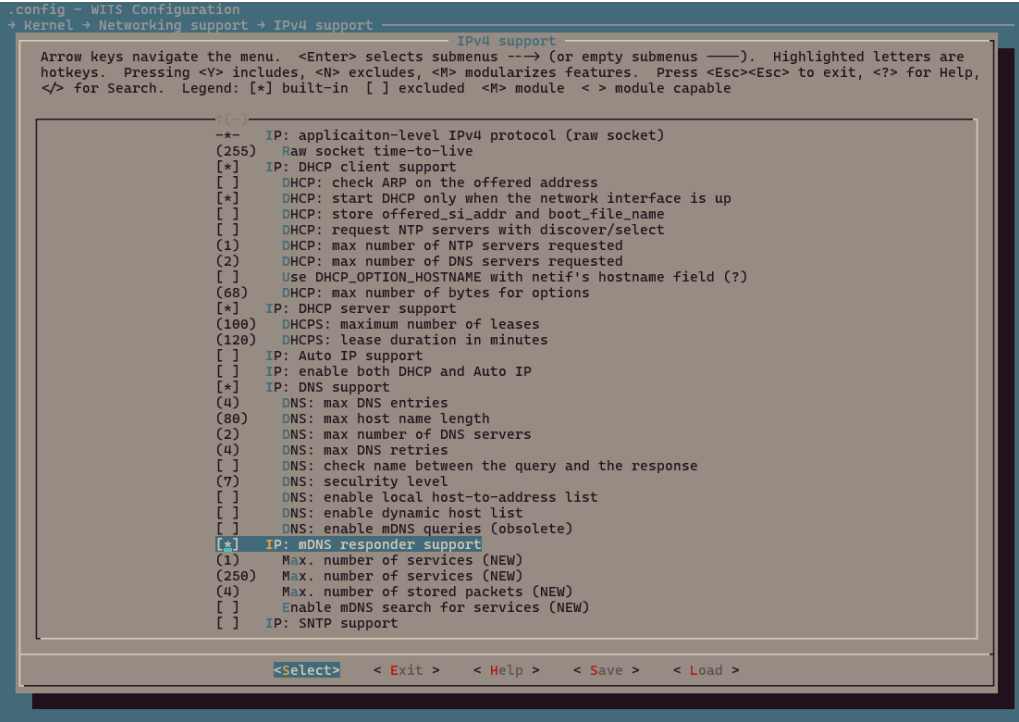
Select Command Line Interface -> Networking utilities -> mdns
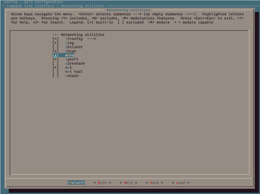
Exit and save.
Build wits-mcuboot.bin.
$ make
Please refer to SDK Getting Started Guide to download the image and run it on the TLSR9118 EVK. Then the relevant CLI commands can be verified available or not.
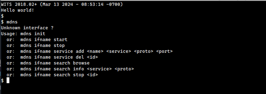
API
The mDNS API provides the following set of functions to initialize and set up the mDNS server and send queries to search for services available on nearby devices.
-
mdns_resp_init
-
mdns_resp_add_netif
-
mdns_resp_remove_netif
-
mdns_resp_add_service
-
mdns_resp_del_service
-
mdns_search_service
-
mdns_search_stop
Note that these functions must be protected by lwIP core locks, as there are shared resources that will be accessed by lwIP TCP/IP core threads. Refer to the mdns() CLI entry function in mdns.c.
Initialize and Set up the mDNS Responder
void mdns_resp_init(void)
Initialize the mDNS responder will open a UDP socket on port 5353.
The corresponding CLI command:
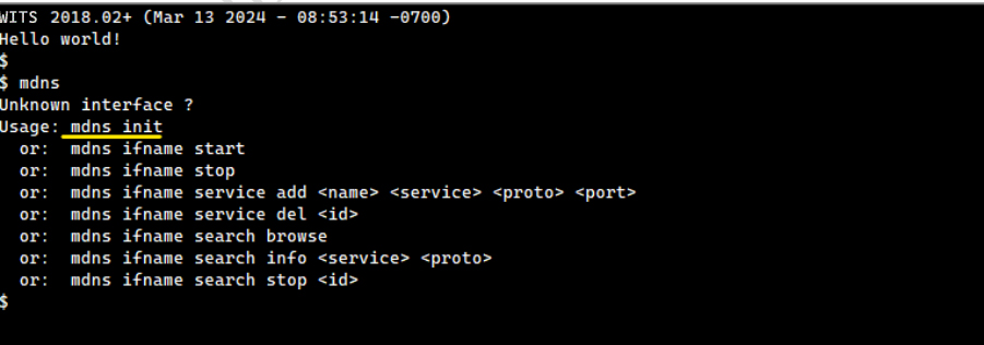
err_t mdns_resp_add_netif(struct netif *netif, const char *hostname)
Activate the mDNS responder for network interface.
| Parameter | Description |
|---|---|
| netif | Network interface to be activated |
| hostname | The name to use. For hostname query, .local will answer with the IP address of that interface. |
Return value: eRR_OK if netif is added, err_t otherwise.
The corresponding CLI command:
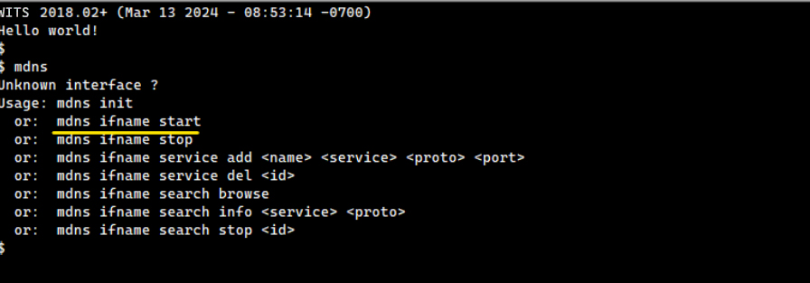
err_t mdns_resp_remove_netif(struct netif *netif)
Stop responding to mDNS query on this interface, leave the multicast group, and release help structure and any of its services.
| Parameter | Description |
|---|---|
| netif | Network interface to be removed |
Return value: ERR_OK if netif is removed, err_t otherwise.
The corresponding CLI command:
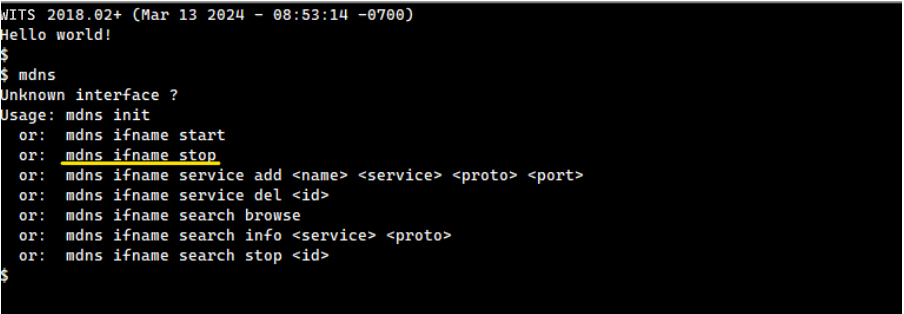
Manage mDNS Responder Service
s8_t mdns_resp_add_service(struct netif *netif, const char *name, const char *service, enum mdns_sd_proto proto, u16_t port, service_get_txt_fn_t txt_f, void *txt_data)
Add a service for the selected network interface.
| Parameter | Description |
|---|---|
| nefit | The web interface on which you want to publish this service. |
| name | Name of the service. |
| service | Service type, e.g. "_http". |
| proto | Service protocol, DNSSD_PROTO_TCP ("_tcp") for TCP, DNSSD_PROTO_UDP ("_udp") for others. |
| port | The port on which the service monitors. |
| txt_fn | Callback for getting TXT data. It is called every time a TXT reply is created to allow dynamic reply. |
| txt_data | Pointer to user data for txt_fn. |
Return value: service_id if the service is added to netif, err_t otherwise.
The corresponding CLI command:
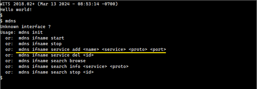
err_t mdns_resp_del_service (struct netif *netif, u8_t slot)
Remove a service on the selected network interface.
| Parameter | Description |
|---|---|
| netif | The network interface from which the service should be removed. |
| slot | mdns_resp_add_service returned service slot number. |
Return value: eRR_OK if the service is removed from netif, err_t otherwise.
The corresponding CLI command:
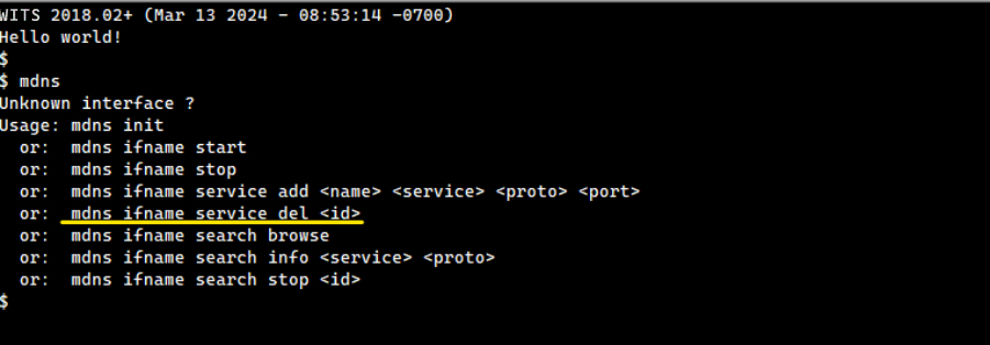
Start Service Query
err_t mdns_search_service (const char *name, const char *search, enum mdns_sd_proto proto, struct netif *netif, search_result_fn_t result_fn, void *arg, u8_t *request_id)
Search for specific service on web.
| Parameter | Description |
|---|---|
| name | Name of the service. |
| service | Service type, e.g. "_http". |
| proto | Service protocol, DNSSD_PROTO_TCP ("_tcp") for TCP, DNSSD_PROTO_UDP ("_udp") for others. |
| netif | The web interface that sends the search request. |
| result_fn | Send a callback for received answers. It is called for each answer in the response frame that matches the sent request. |
| arg | A pointer to the user data for result_fn. |
| request_id | The request identifier returned to allow stopping it. |
Return value: ERR_OK if the search request is created and sent, err_t otherwise.
The corresponding CLI command:
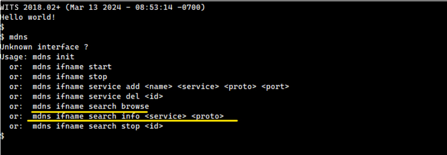
Both CLI commands use this API, but with different parameters.
Stop Service Query
void mdns_search_stop(u8_t request_id)
Stop a search request.
| Parameter | Description |
|---|---|
| request_id | The search request to be stopped. |
The corresponding CLI command:
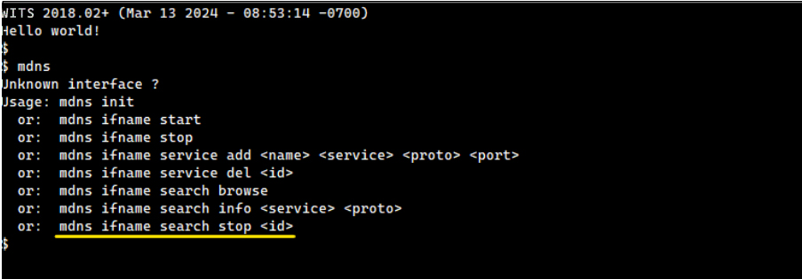
Example
There is no specialized mDNS example application available. Instead, the mDNS CLI commands described above can be used to test its features.
Connect to AP
The Wi-Fi STA CLI command can be used to connect a site interface (e.g., wlan0) to AP.
Refer to the Wi-Fi Software Development Guide to use the Wi-Fi site CLI commands, as there is almost always a one-to-one correspondence between Wi-Fi API functions and Wi-Fi CLI commands.
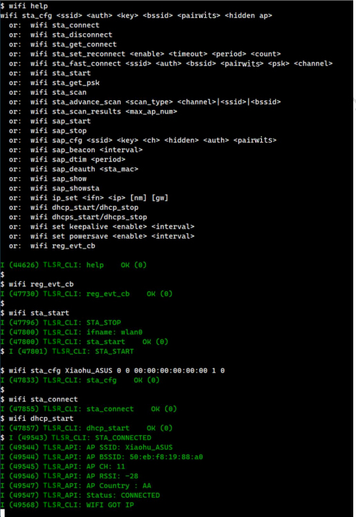
The mDNS responder now answers queries from nearby devices on the same network. To see this, use avahi-browse from a Linux PC connected to the same LAN as the TLSR9118 EVB, as shown below.
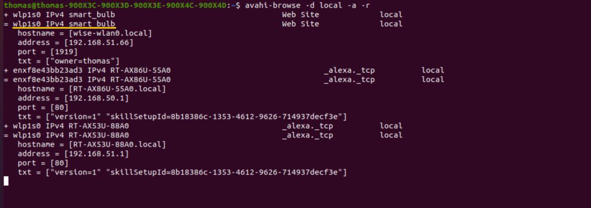
Since the mDNS responder is started, any peer device on the same LAN (such as this Linux PC) can use its local hostname, as shown below.
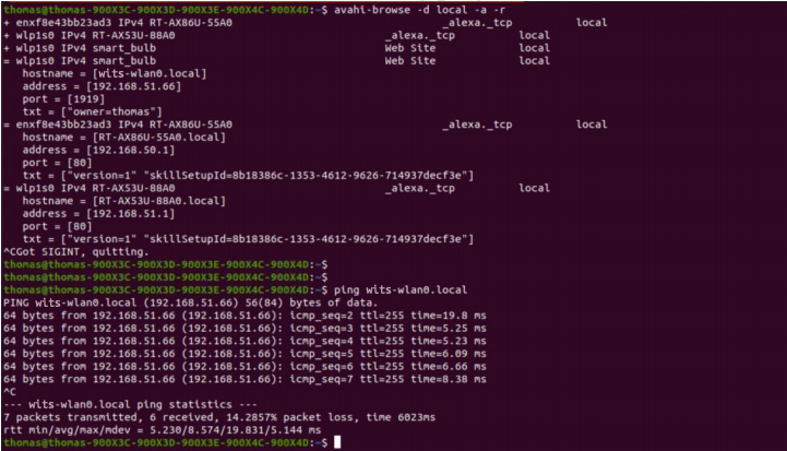
The 'wits-wlan0' is the hostname provided to the mdns_resp_add_netif function via a CLI command. It can be changed to any suitable name in the user application.
SNTP Development Guide
Introduction
The SNTP Development Guide aims to help implement applications that need to run SNTP.
Overview
The TLSR9118 SDK uses SNTP Port for lwIP:
- The API and CLI are located at:
lib/net/sntp.
Build
To use the SNTP API and CLI, users should enable the appropriate features in the build configuration.
$ make tlsr9118s_defconfig
$ make menuconfig
Navigate to Kernel -> Networking support -> IPv4 support -> IP: SNTP support and enable it.
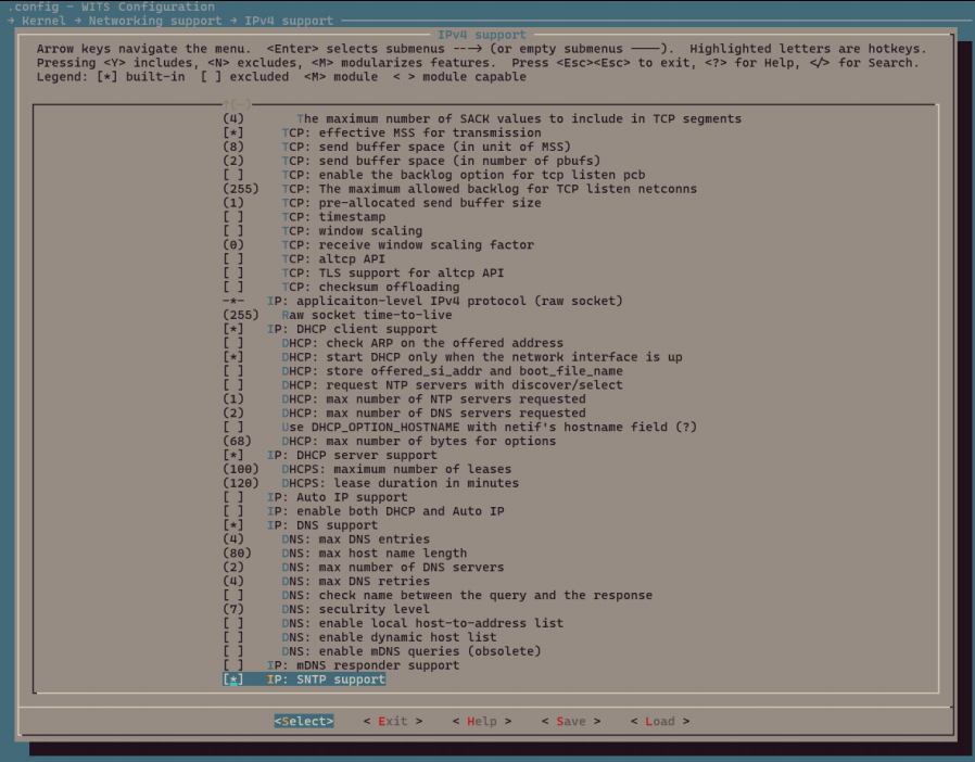
Again, navigate to Command Line Interface -> Networking utilities -> sntp and enable it.
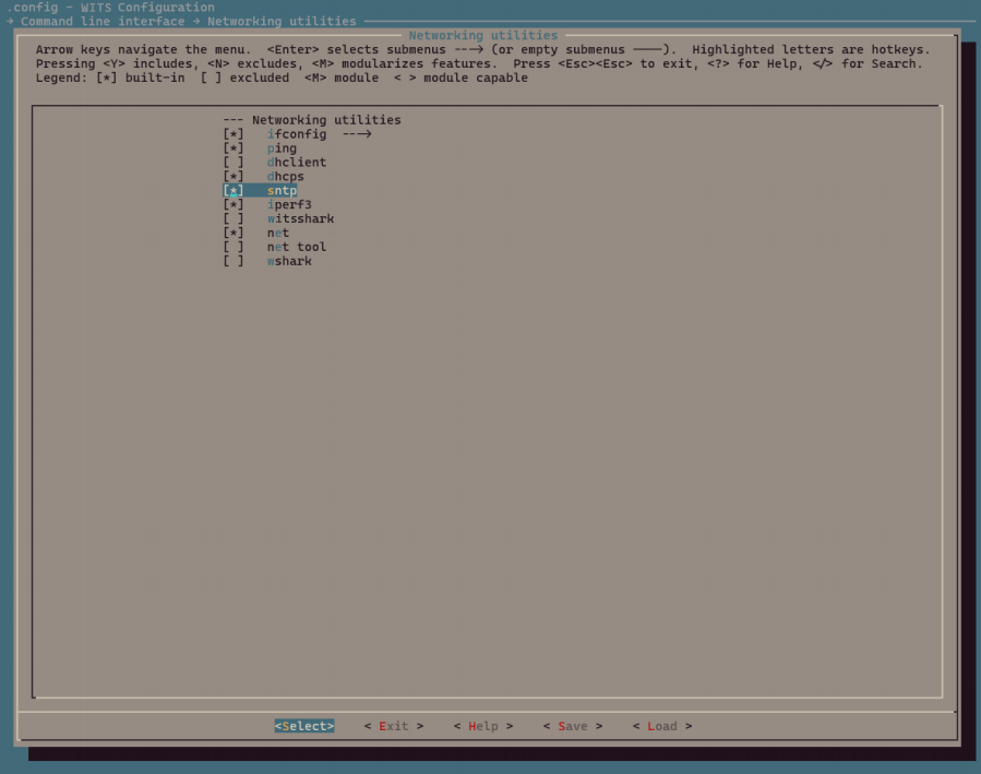
Exit and save, then build wits-mcuboot.bin:
$ make
Please refer to SDK Getting Started Guide to download the image and run it on the TLSR9118 EVK. Then the relevant CLI commands can be verified available or not.
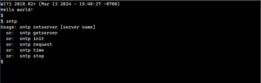
API
The SNTP API provides the following set of functions to set up the SNTP module and send queries to get the network time.
-
sntp_setservername
-
sntp_init
-
sntp_set_time_sync_notification_cb
-
sntp_stop
Setup and Stop
void sntp_setservername(u8_t idx, const char *server)
Initialize one of the NTP servers by name.
| Parameter | Description |
|---|---|
| Idx | The index of the NTP server to be set, must be less than NTP_MAX_SERVERS. |
| Server | The DNS name of the NTP server to be set, which will be resolved on contact. |
The corresponding CLI command:
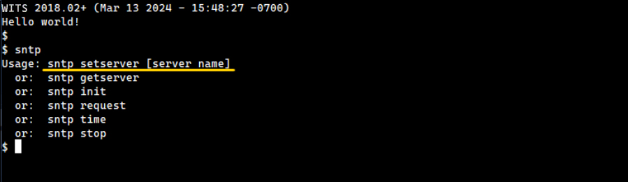
void sntp_set_time_sync_notification_cb(void (*callback)(uint32_t sec, uint32_t us))
Install a callback function that is executed when an update from the SNTP server is available.
| Parameter | Description |
|---|---|
| callback | A callback function that is executed when network time is available. |
The corresponding CLI commands:
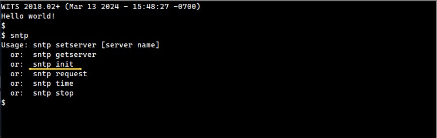
void sntp_stop(stop)
Stop SNTP module.
The corresponding CLI command:
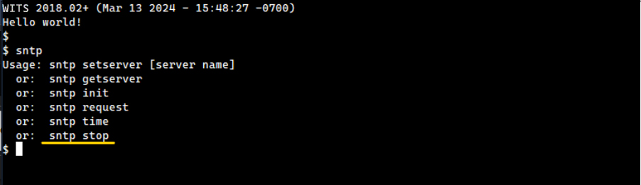
Initiate Time Synchronization Operation
void sntp_init(void)
Initialize this module and send the request immediately or after SNTP_STARTUP_DELAY(_FUNC).
The corresponding CLI command:
Example
There is no specialized SNTP example application. Instead, the SNTP CLI command described above can be used to test its feature.
While the SNTP API can handle the SNTP protocol itself, there should be a way to synchronize it with system time. To do this, the user application can use the gettimeofday and settimeofday functions, which will also be shown in the CLI example.
Connect to AP
The Wi-Fi STA CLI command can be used to connect the site interface, wlan0, to AP. refer to the Wi-Fi Software Development Guide to use the Wi-Fi site CLI command.
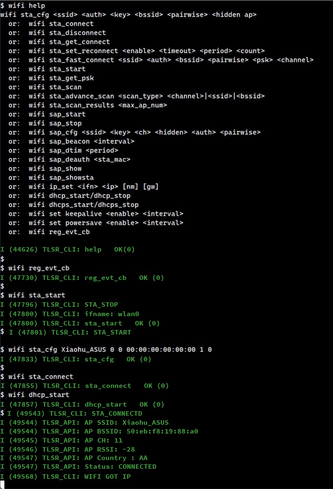
Configure SNTP Server by Name
Use the CLI command sntp setserver [name] to set the SNTP server.

Start SNTP Service
Use the CLI command sntp init to start the SNTP service.
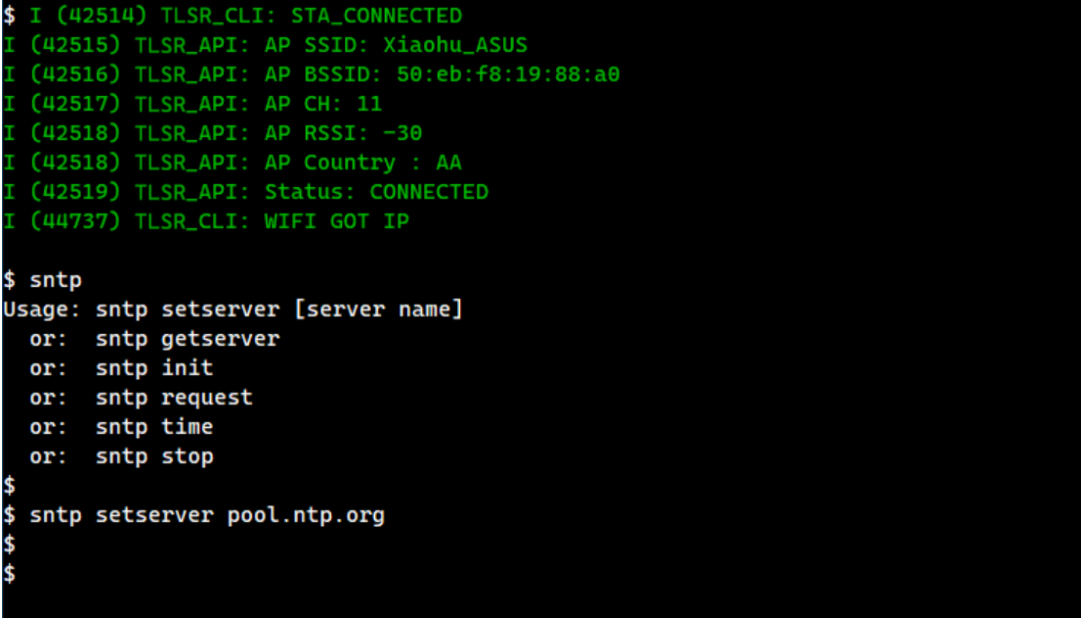
Now the SNTP client request will be sent to the configured server, which will return the current network time.
The CLI command sntp init also registers a callback function sntp_set_time_sync_notification_cb, which demonstrates how to synchronize the system's local time with the network time returned by the SNTP server.
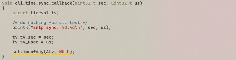
After this callback function is called, the system time will be synchronized with network time, which will be retrieved by calling settimeofday. This is demonstrated by the CLI command sntp time shown below:
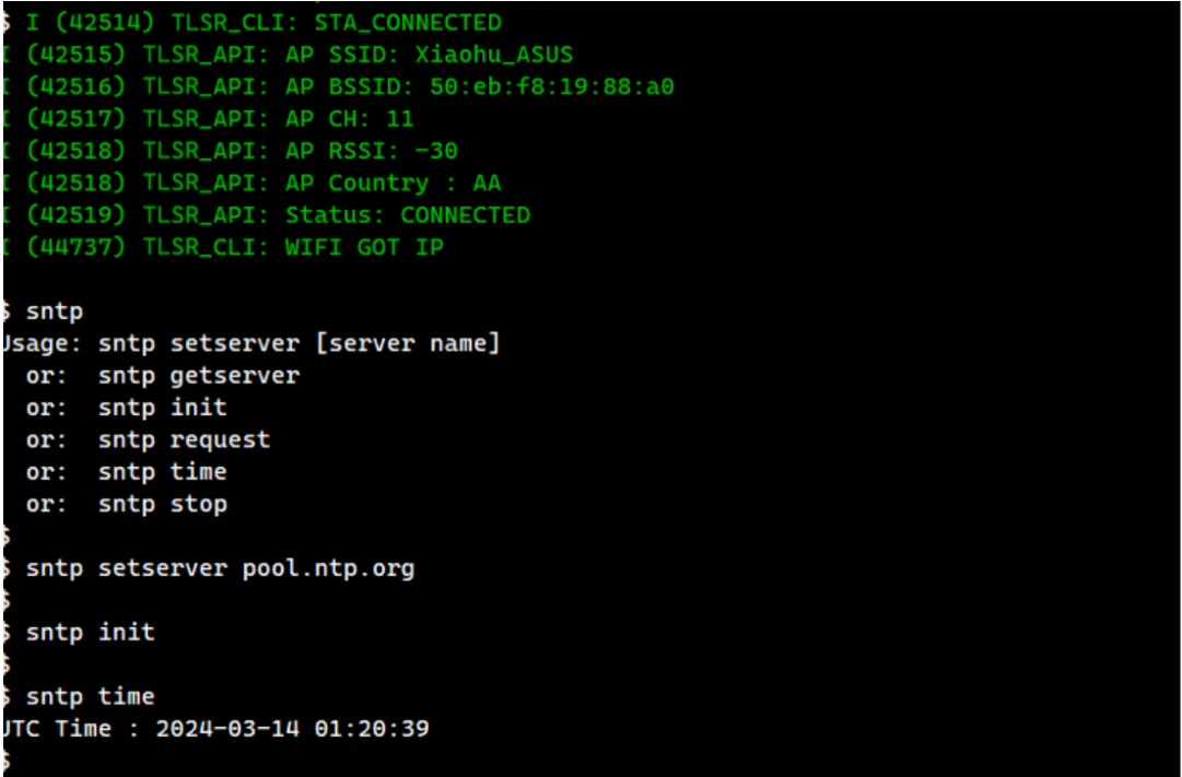
HTTP Server Development Guide
The HTTP Server Development Guide aims to help implement applications that need to run an HTTP server.
Overview
The TLSR9118 SDK uses the esp_http_server module of ESP-IDF:
- API location:
lib/net/esp_http_server. - Demo path:
api/examples/protocols/http_server.
Example
To run the HTTP server example, follow these steps:
Build Configuration
Build configuration with the following settings.
- Select the HTTP server example as the main application.
  $ make tlsr9118_defconfig
  $ make menuconfig
-
Navigate to Applications -> Protocols Demo.
-
Select Protocols Demo -> HTTP Server Demo.
-
Exit and save.
Set Wi-Fi Parameters
Set Wi-Fi parameters as follows.
$ make menuconfig
-
Navigate to Applications -> Common -> include WI-FI Configuration.
-
Enter the parameters in DEMO WI-FI Configuration (use the Help menu if necessary).
-
Exit and save.
Build wits-mcuboot.bin
$ make
- Refer to the SDK Getting Started Guide to download the image and run it on the TLSR9118 EVK.
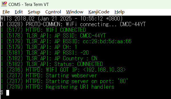
Running Example
This example registers 3 URIs, each serving a different purpose:
-
/hello: URI used to respond to the client's GET HTTP method.
-
/echo: URI used to respond to the client's POST HTTP method.
-
/ctrl: URI used to respond to the client's PUT HTTP method.
This example requires an HTTP client and it should be on the same network as the TLSR9118 EVB hosting the HTTP server so that they can connect and exchange HTTP messages between them.
There may be many different options for running an HTTP client. In this example, the curl command on a Linux PC connected to the same network as the TLSR9118 EVB is used.
Test URI
- /hello: Test by sending a GET request.

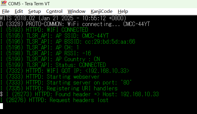
- /echo: Test by sending a POST request.

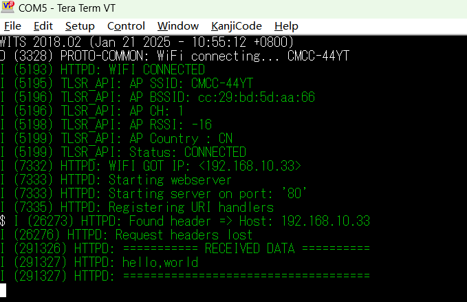
- /ctrl: Test by sending a PUT request. Putting a "0" into /ctrl will unregister the /hello and /echo URIs, while putting a "1" into /ctrl will register those URIs.
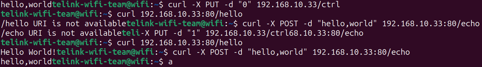
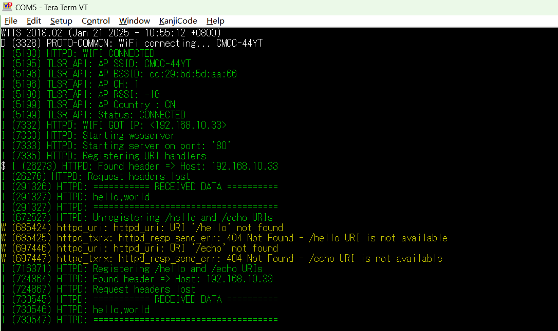
HTTP Client Development Guide
Overview
The HTTP Client Development Guide aims to help implement applications that need to run HTTP clients on the TLSR9118 platform.
The TLSR9118 SDK uses the esp_http_client module from ESP-IDF:
-
API path:
lib/net/esp_http_client -
Demo path:
api/examples/protocols/http_client
Demo Configuration and Build
To run the HTTP Client Demo, follow these steps.
Set Build Configuration
(1) Select HTTP Client Demo as the main application:
$ make tlsr9xxxs_defconfig
$ make menuconfig
(2) In the menuconfig interface, navigate to the following options:
-
Applications -> Protocols Demo -
Select:
Protocols Demo -> HTTP Client Demo -
Libraries/middleware -> net -> ESP HTTP Client -
Select:
Enable HTTP Basic Authentication -
Select:
Enable HTTP Digest Authentication
(3) Exit and save the configuration.
Set Test HTTP Server
(1) Navigate to Applications -> Example Configuration in the menuconfig interface.
(2) Modify the test HTTP server settings as necessary.

Set Wi-Fi Parameters
(1) Open the menuconfig interface:
$ make menuconfig
(2) Navigate to Applications -> Common -> include WI-FI Configuration.
(3) Enter Wi-Fi parameters in DEMO WI-FI Configuration. If necessary, use the Help menu to view the detailed description of each item.
(4) Exit and save the configuration.
Build wits-mcuboot.bin
(1) Build project:
$ make
(2) Please refer to SDK Getting Started Guide to download the generated image to TLSR9118 EVK and run it.
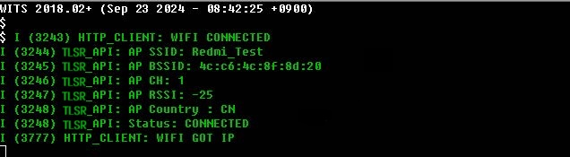
Use the HTTP Client
The HTTP Client API provides multiple types of HTTP request features and supports authentication, data streaming, and HTTPS connection.
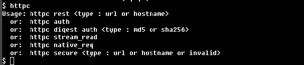
Basic HTTP Request
The esp_http_client API supports the execution of GET, POST, PUT, PATCH and DELETE requests. Once a connection is established, multiple requests can be initiated before closing the connection. This section focuses on common cases for testing the REST API using URL or hostname.
- Test with URL
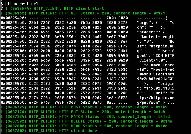
- Test with hostname
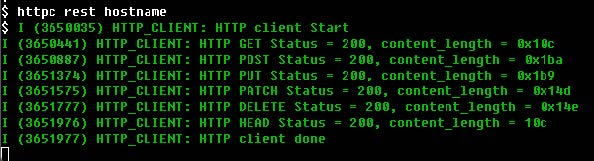
HTTP Authentication
The HTTP client supports both Basic and Digest authentication methods. Digest authentication supports MD5 and SHA-256 algorithms.
- Basic Authentication
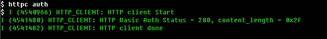
- MD5 Authentication
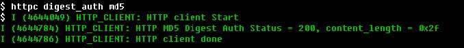
- SHA-256 Authentication
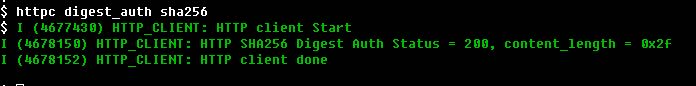
HTTP Data Streaming
- For application scenarios that require active control of data exchange (e.g., real-time data streaming), HTTP streaming mode can be used. The execution flow of the application is different from that of a regular request.
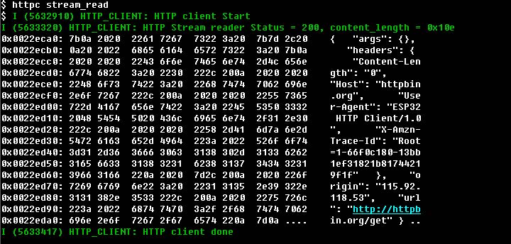
HTTP Native Interface
The HTTP client provides underlying API that enable fine-grained control over HTTP connection.
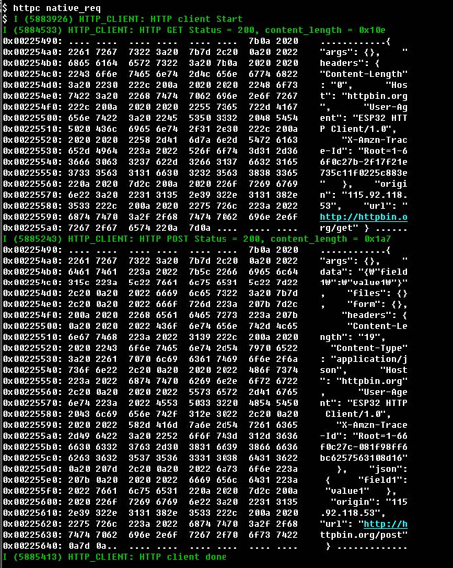
HTTPS Request
The HTTP client supports SSL connection using mbed TLS. It is recommended using www.howsmyssl.com as a test server for demonstration.
Get Root CA Certificate
For HTTPS requests, the root CA certificate (PEM file) is required. The following example demonstrates how to get the root CA certificate using openssl:
openssl s_client -showcerts -connect www.howsmyssl.com:443 < /dev/null
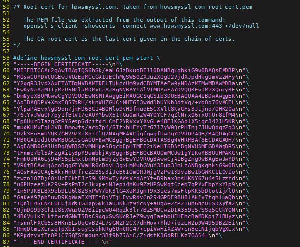
HTTPS Time Synchronization
For HTTPS authentication, the device time must be synchronized.The TLSR9118 SDK supports time synchronization using STNP.
- If time is not synchronized
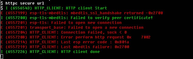
- If time is synchronized
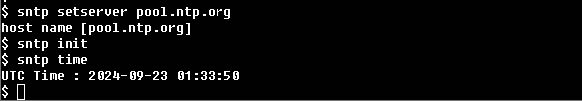
- The HTTPS request after time synchronization

MQTT Development Guide
The MQTT Development Guide aims to help implement applications that require MQTT client feature.
Overview
TLSR9118 SDK uses coreMQTT-Agent and the underlying coreMQTT:
-
API location:
lib/mqtt/coreMQTT-Agent,lib/mqtt/coreMQTT. -
Demo path:
api/examples/protocols/mqtt.
Example Operation Guide
Follow the steps below to run the MQTT example on the TLSR9118 platform.
Configure Build Configuration
(1) Select the MQTT example as the main application.
$ make tlsr9118s_defconfig
$ make menuconfig
(2) Navigate to: Applications -> Protocols Demo.
(3) Select: Protocols Demo -> MQTT Demo.
(4) Exit and save the configuration.
Set Wi-Fi Parameters
(1) Open the configuration menu:
$ make menuconfig
(2) Navigate to: Applications -> Common -> include WI-FI Configuration.
(3) Enter the desired Wi-Fi parameters in the following path: DEMO WI-FI Configuration (use the Help menu to see a description of each option if necessary).
(4) Exit and save the configuration.
Configure MQTT Client Parameters
(1) Open the configuration menu again:
$ make menuconfig
(2) Navigate to: Applications -> MQTT demo.
(3) Modify the MQTT client parameters as needed.
(4) Build the firmware image file: wits-mcuboot.bin.
$ make
(5) Refer to SDK Getting Started Guide for guidance on how to download the generated wits-mcuboot.bin image file and burn it to the TLSR9118 development board.
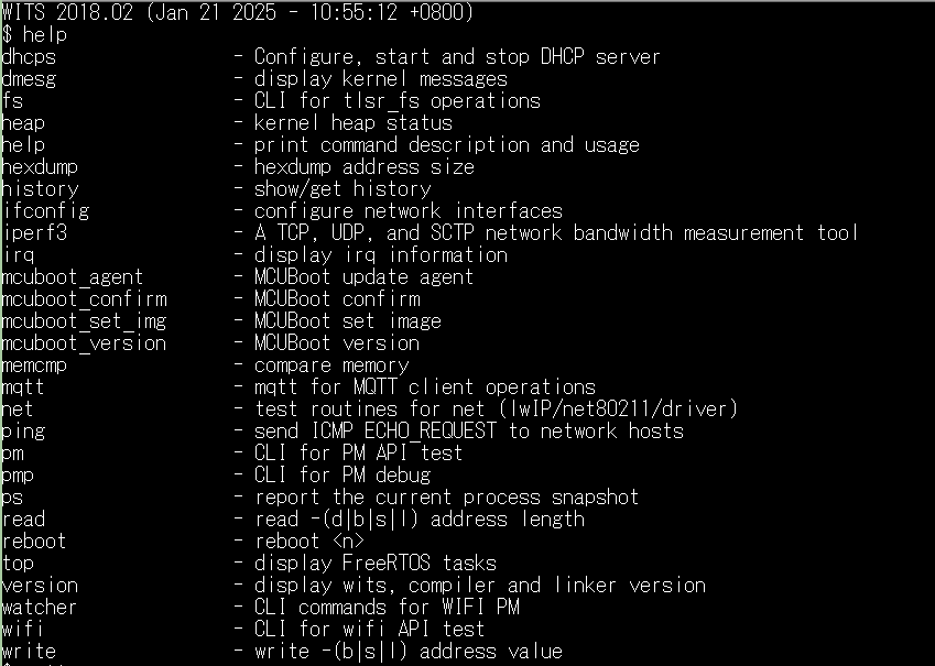
Running Example
To run the MQTT example, an independent MQTT client is required that interacts with the same MQTT server test.mosquitto.org, either as Publisher or Subscriber. The PC version of Eclipse mosquito is used as the test client in this example.
- The example allows interactive test with MQTT client using CLI command.
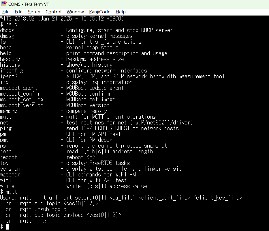
Initialize MQTT Client
The MQTT client can be initialized and started with the mqtt init CLI command. This command takes the following parameters:
| Parameter | Meaning | Must or Optional | Example |
|---|---|---|---|
| url | URL of the MQTT server | M (must) | test.mosquitto.org |
| port | Port number of the MQTT server | M (must) | 1883 (plaintext transmission); 8883 (encrypted transmission without authentication); 8884 (encrypted transmission with authentication) |
| secure | 0: plaintext TCP transmission; 1: TLS transmission | M (must) | - |
| ca_file | Full path of CA certificate file | M if secure is 1 | /path/to/ca.crt |
| client_cert_file | Full path to the client certificate file | Optional if secure is 1 | /path/to/client.crt |
| client_key_file | Full path to the client key file | Optional if secure is 1 | /path/to/client.key |
Transmission Using Plaintext TCP
The following is a CLI command example to initialize and start an MQTT client using plaintext TCP transmission. This client will connect to the configured MQTT server.
The Wi-Fi parameters should be configured during the build process. When the mqtt init command is run, the TLSR9118 device will automatically connect to the configured access point (AP).
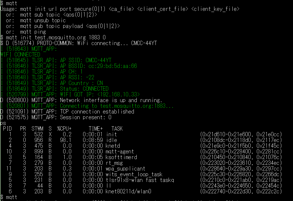
Encrypted Transmission Using TLS (Encryption Only)
To connect via TLS, the appropriate CA certificate needs to be stored on the file system. For example, the TLSR9118 MQTT client can use a CA certificate (mosquitto.org.crt) to connect to port 8883 on test.mosquitto.org.
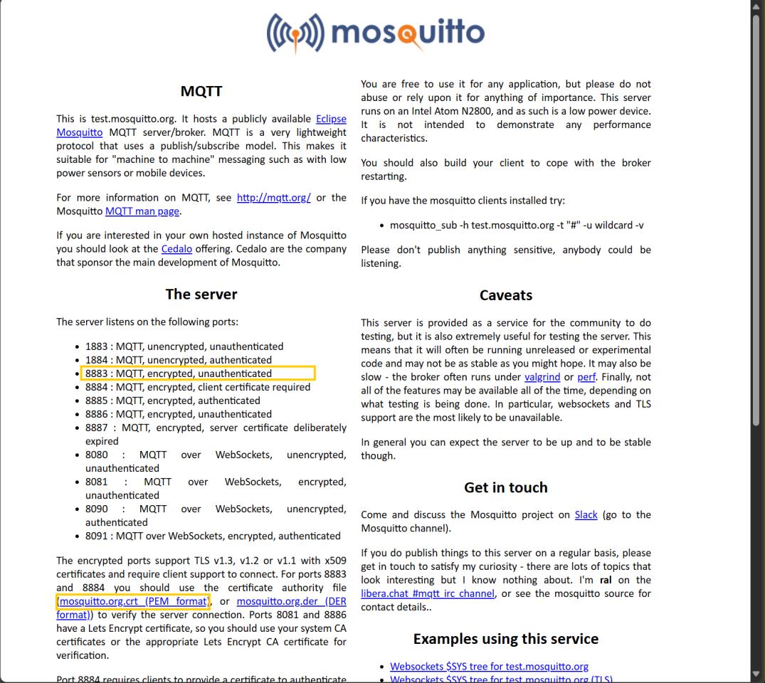
Steps:
(1) Download CA certificate from test.mosquitto.org to PC.
(2) Use the fs load CLI command to load the certificate file into the file system of the target device.
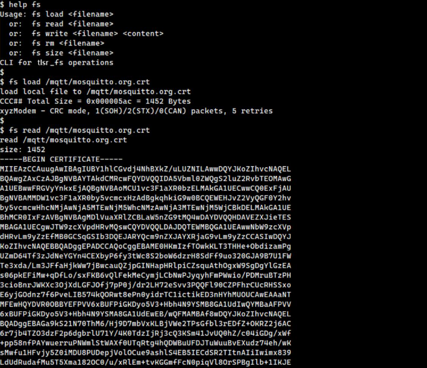
(3) File transfer can use the YMODEM protocol, depending on the terminal program used. For Tera Term:
- Go to
Transfer -> YMODEM -> Sendand select the certificate file to transfer.
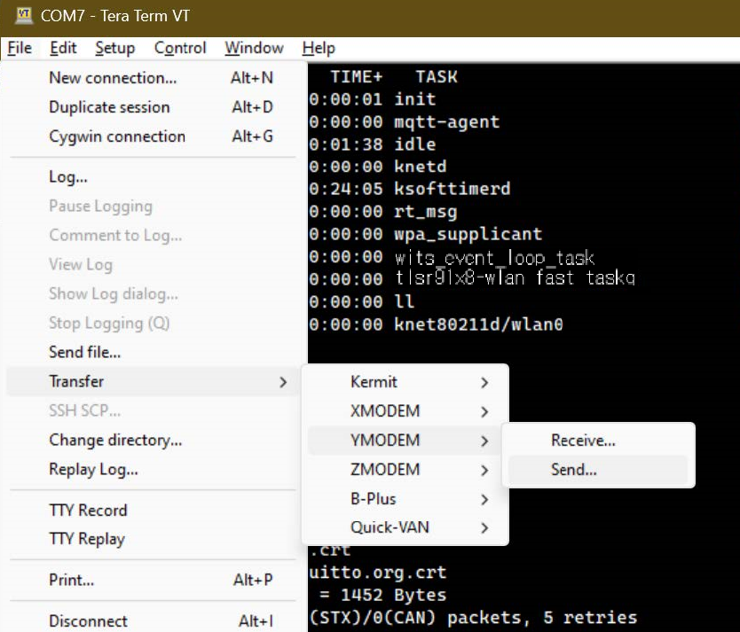
(4) After the transfer is complete, enable TLS initialization and start the MQTT client.
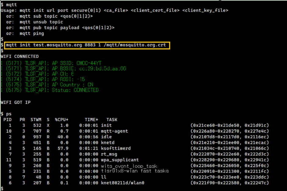
Encrypted Transmission with Client Authentication Using TLS
To perform client authentication, it is needed to prepare client certificate and client key. These files can be generated using the openssl tool, and a detailed guide to generate them is available on the test.mosquito.org website.
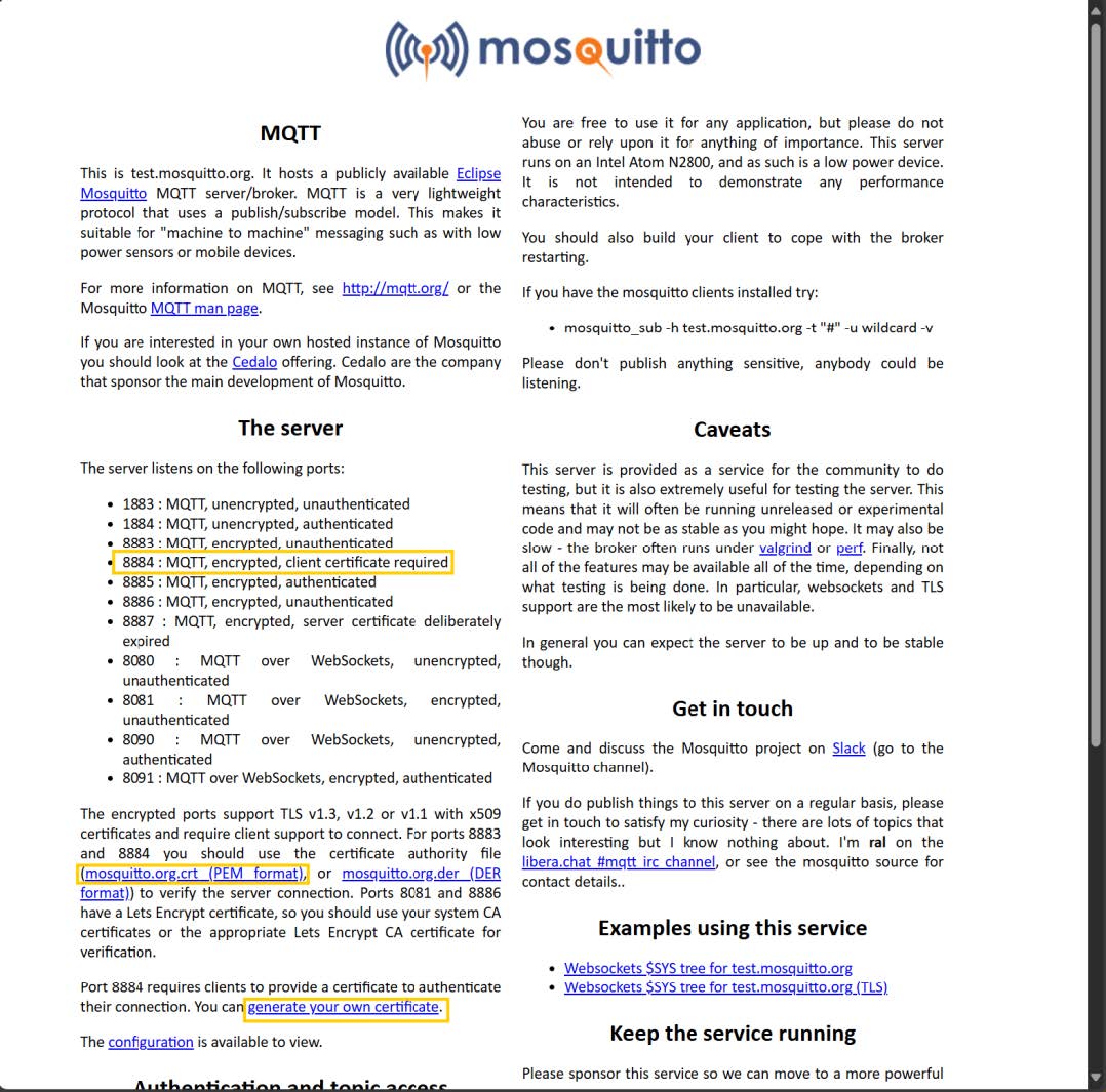
Steps:
(1) Generate client certificate and key.
(2) Use the fs load CLI command to load the client certificate and key file into the target device (in the same way as CA certificate is loaded).
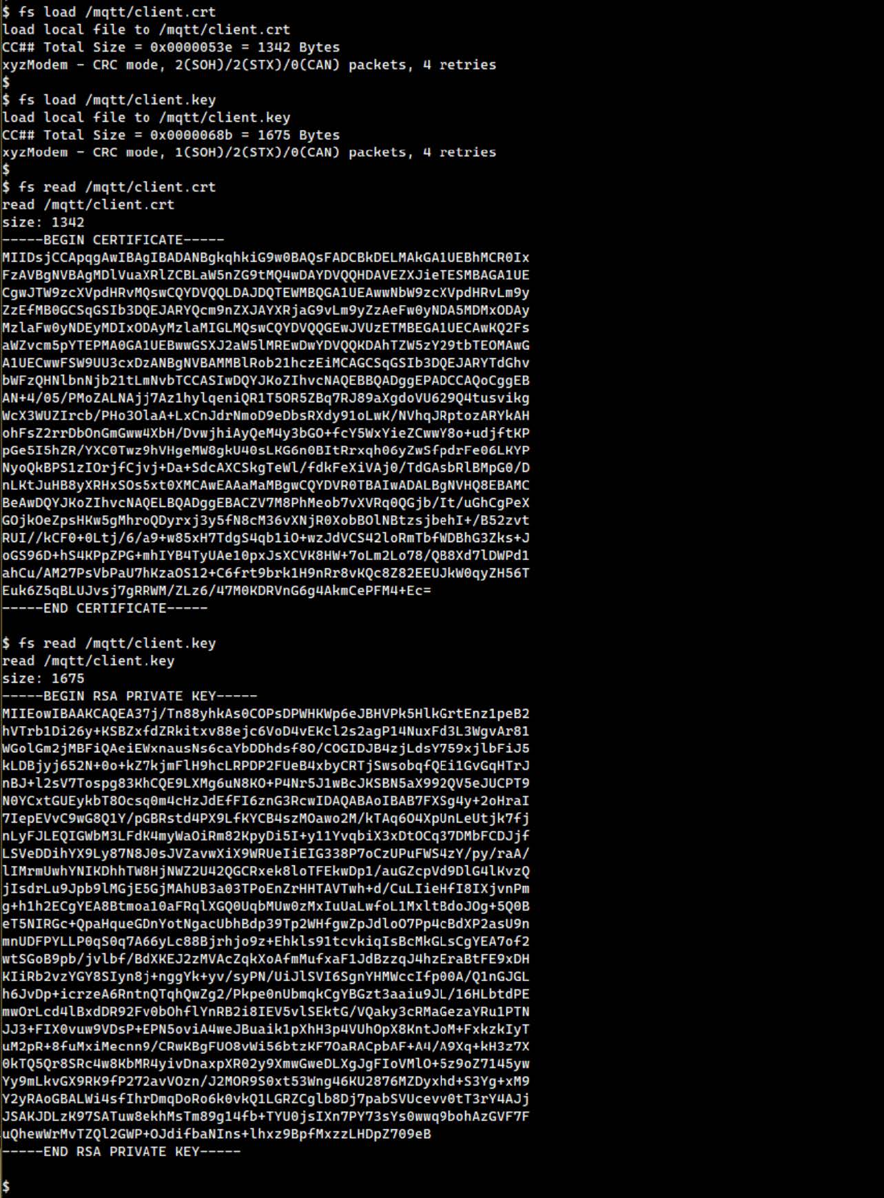
(3) Enable TLS and perform client authentication, initialize and start MQTT client.
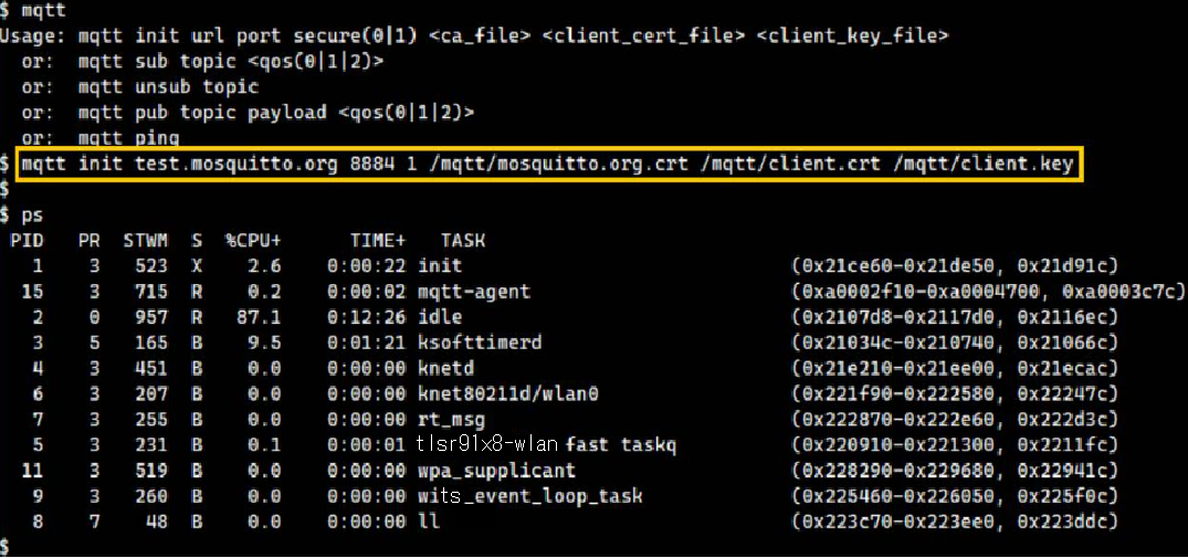
Test Subscribing to Specific Topic
To test subscribing to specific topic, follow these steps:
(1) Subscribe to the topic using MQTT client's CLI command:
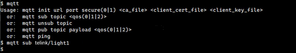
(2) Use another MQTT client (e.g., Eclipse Mosquitto) on the PC to publish messages to the same topic.

(3) Check the messages received by the TLSR9118 MQTT client. The message should be displayed in the terminal.
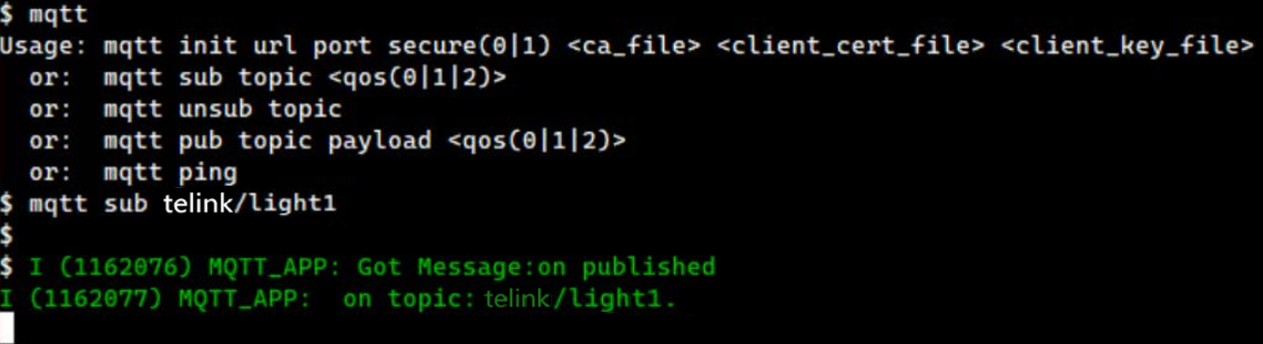
Test Publishing Message to Specific Topic
To test publishing message to specific topic, follow these steps:
(1) Subscribe to the topic in the PC's MQTT client.

(2) Use the CLI command of the TLSR9118 MQTT client to publish message to the same topic.

(3) Check the message received by PC client; the message should show what the TLSR9118 client has published.

CoAP Development Guide
Introduction
The CoAP Development Guide aims to help implement applications on the TLSR9118 platform using the Restricted Application Protocol (CoAP).
Overview
The TLSR9118 SDK integrates the Libcoap library to facilitate CoAP-based communication. libcoap resources are organized as follows:
-
API Location:
lib/net/coap -
Demo path:
api/examples/protocols/coap
The CoAP module in TLSR9118 can run as a CoAP server and/or CoAP client. For more information on using libcoap API, see Libcoap Documentation.
Build Instruction
To build and run CoAP demo with CLI support, follow these steps:
(1) Enable Required Features: First enable the required features in build configuration:
\$ make tlsr9xxxs_4m_defconfig
\$ make menuconfig
(2) Configure Build Options: Select CoAP demo options by configuring the menu navigation:
-
Applications -> Applications -> Protocols Demo -
Applications -> Protocols Demo -> CoAP Demo -
Applications -> CoAP Demo to configure additional options
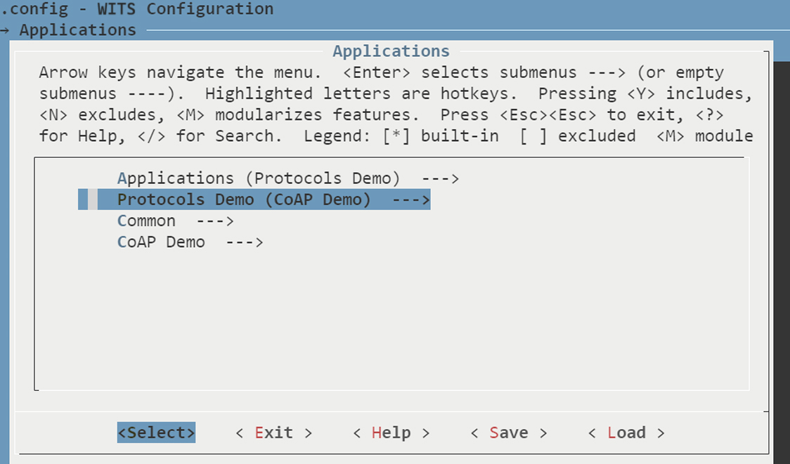
(3) Save Configuration: Exit the configuration menu and save the changes.
(4) Build Firmware: Build wits-mcuboot.bin file:
$ make
(5) Deploy Firmware: Refer to the SDK Getting Started Guide for instructions on downloading the image and running it on the TLSR9118 EVK.
(6) Verify CLI Command: After deployment, verify the availability of the relevant CLI commands.
CoAP Server Program Demo
Connect to Access Point (AP)
To connect the site interface (wlan0) to access point (AP), use Wi-Fi Station (STA) Command Line Interface (CLI) command. For comprehensive instructions on using these commands, see the Wi-Fi Software Development Guide. This guide provides a detailed mapping between Wi-Fi API functions and their corresponding CLI commands.
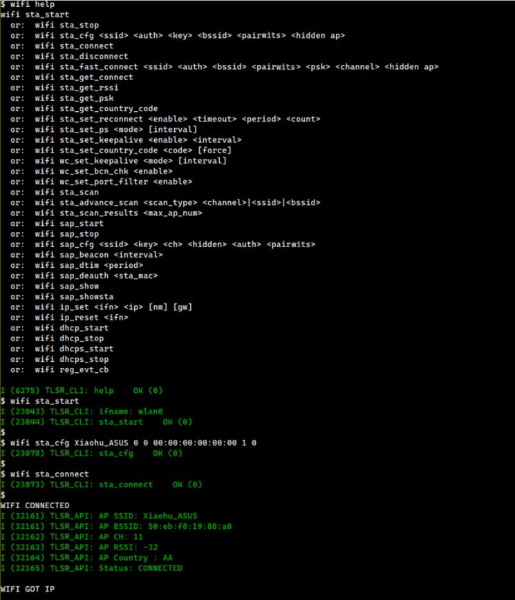
Note
- It is recommended to avoid using the wifi reg_evt_cb command as it interferes with the demo application by blocking the reception of Wi-Fi event notifications.
Run CoAP Server Program
This section describes how to start and stop the CoAP Server program using Command Line Interface (CLI) commands.
Start CoAP Server Program
To start the CoAP server program, the basic command is:
coap_server start
However, this command starts the CoAP server program using default configuration and does not have any security features. To customize the server settings, the coap_server start command supports several options:
coap_server start [-d max] [-g group] [-p port] [-A address] [-N] [[-k key] [-h hint]] [[-c certfile] [-m] [-C cafile]] [-E oscore_conf] [-j keyfile]
Each option is described in detail below.
General Options
-
-d max: Allow dynamic resources to be created via the PUT method up to the specified limit (max). If the limit is reached, a 4.06 error code is returned until one of the dynamic resources is deleted. -
-g group: Join the specified multicast group at startup. -
-p port: Specify the port on which to listen for incoming connections at the given address. If (D)TLS is supported, the server program also listens for (D)TLS connections on port + 1. If not specified, the default port is 5683. -
-A addr: Set the local address of the interface on which the server program will listen. -
-N: Send non-confirmable messages to observable responses. If this option is not specified, confirmable responses will be sent by default. Even if set, every fifth response is still confirmable as required by RFC 7641.
Pre-Shared Key (PSK) Options
-
-h hint: Specify the pre-shared key identifier for inbound connection. The default value is "CoAP". If defined, this field cannot be empty. -
-k key: Define the pre-shared key used for inbound connection. If defined, this field cannot be empty. Note: If the -c cafile option is defined, the -k key must also be defined to enable the server program to support both PSK and PKI.
Public Key Infrastructure (PKI) Options
-
-c certfile: Use specified PEM file containing certificate and private key information. Note: If the -k key is defined, the -C cafile must also be defined to enable the server program to support both PSK and PKI. -
-m: Instruct the server program to cache the certificate file. -
-C cafile: Specify a PEM file containing the CA certificate used to sign the certifile defined by -c certfile. If defined, this CA certificate is provided to the client during TLS setup, triggering client certificate validation. If the certfile is self-signed, the same filename must be used for both the certfile and the cafile to trigger validation (e.g., -c certfile -C certfile). -
-j keyfile: Define the keyfile used by PKI.
OSCORE Options
-E oscore_conf: Specify the OSCORE configuration file.
Example commands
The following example starts a PKI and OSCORE-enabled CoAP server program with specified certificate and key file:
coap_server start -j /coap/certs/coap_server.key -C /coap/certs/coap_ca.pem -c /coap/certs/coap_server.crt -m -E /coap/oscore/coap_server_oscore.conf
Note
- Ensure that all certificate files are uploaded before starting the server program, refer to Uploading Certificate Files.
Stop CoAP Server Program
To stop the CoAP server program and release the allocated resources, use the following command:
coap_server stop
Enable mDNS Responder (optional)
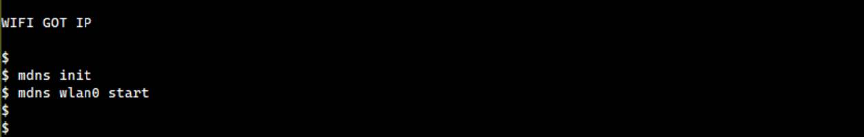
Enabling mDNS (multicast DNS) responder is an optional step. If choose not to enable this feature, the device's IP address can be used directly in subsequent steps.
CoAP Client Demo Program
Run CoAP Client
The CoAP client demo program supports a variety of command line interface (CLI) commands, including the following:
-
GET/PUT/POST/DELETE: Perform GET, PUT, POST, or DELETE requests.
-
GET/PUT/POST/DELETE with Security: Perform GET, PUT, POST, or DELETE requests with security enabled.
-
Security Modes: Support PSK (Pre-Shared Key) and PKI (Public Key Infrastructure) security.
-
OSCORE: Object Security for Constrained RESTful Environments (OSCORE).
-
Subscription/Observation: Subscribe or observe the resource.
Note
- Using the coap:// scheme to disable security, while the coaps:// scheme will enable security based on the configured settings.
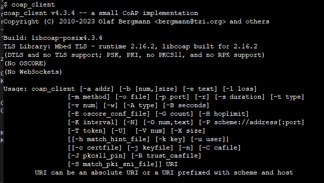
Connect to AP: Connect to AP as described in section Run Coap Server Program.
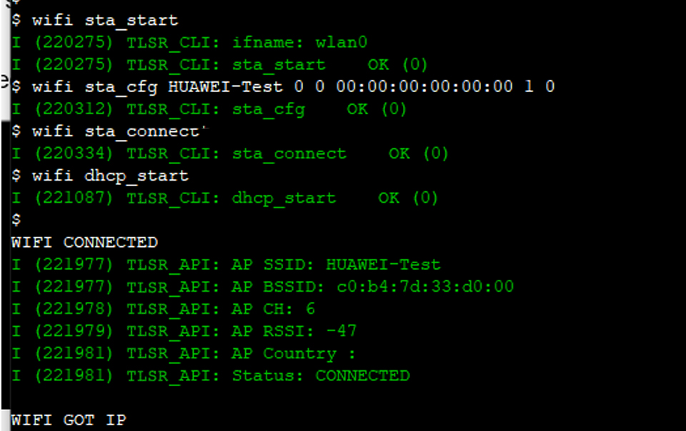
Note
- Make sure that the PKI and OSCORE files are loaded into the system before running the CoAP client demonstration.
CoAP Client Commands
Basic GET Requests
coap_client -m get coap://californium.eclipseprojects.io
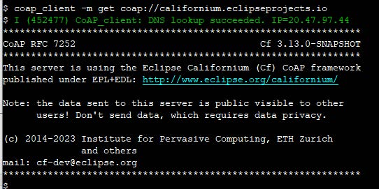
Use Non-Confirmable messages for broadcast operation.
coap_client -m get coap://255.255.255.255 -N
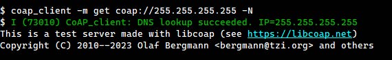
GET Request Based on PSK Security
coap_client -m get -u password -k sesame coaps://californium.eclipseprojects.io
GET Request Based on PKI Security
coap_client -m get -C /coap/certs/coap_ca.pem -c /coap/certs/coap_client.crt -j /coap/certs/coap_client.key coaps://californium.eclipseprojects.io
GET/PUT/DELETE Operation
coap_client -m get coap://[192.168.3.18]/Telink
coap_client -m put coap://[192.168.3.18]/Telink -e "ABC"
coap_client -m get coap://[192.168.3.18]/Telink
coap_client -m delete coap://[192.168.3.18]/Telink
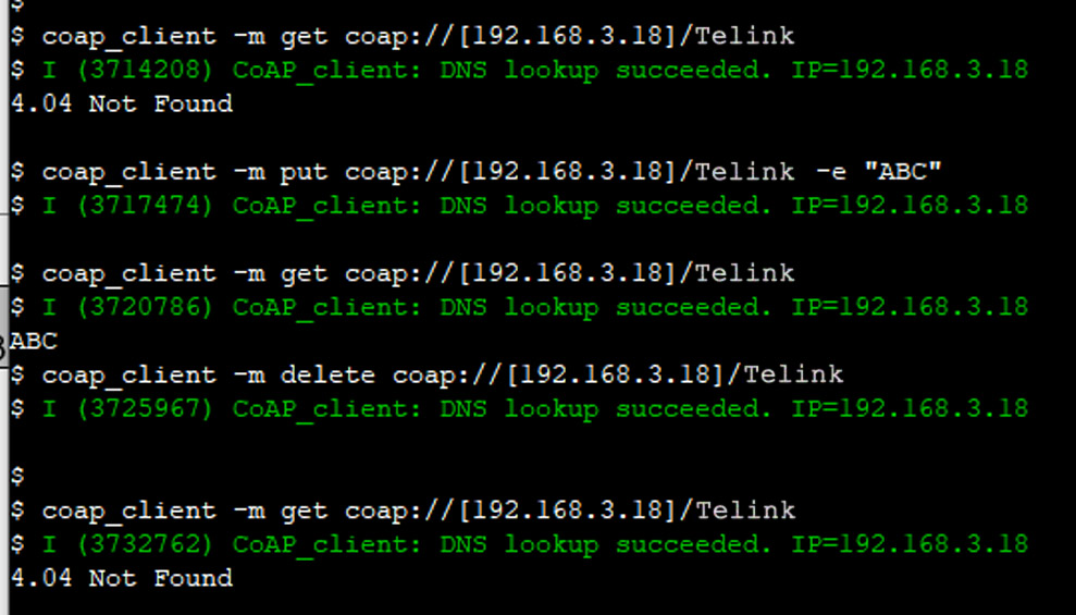
Note
- Make sure that the peer CoAP Server has registered the correct URI. If use TLSR9118 as the CoAP Server, use the
-d maxoption when turning on the CoAP Server, as described in Section General Options. In this example, the peer CoAP Server is started using the commandcoap_server start -d 1.
Subscribe/Observe Resource
-s duration: The specified duration (in seconds) of the subscribed/observed resource:
coap_client -s 60 -m get coap://\[192.168.3.18\]/time
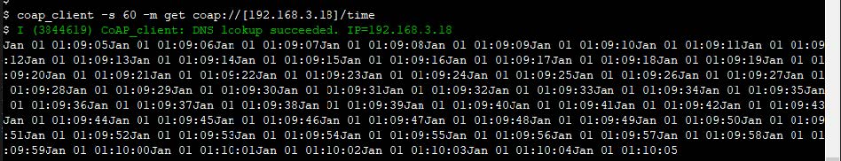
Run with OSCORE Security
To use OSCORE security, make sure that "Use OSCORE as CoAP security mechanism" is enabled in the configuration menu.
GET Request Based on OSCORE Security
coap_client -m get -E /coap/oscore/coap_client_oscore.conf coap://californium.eclipseprojects.io
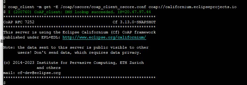
GET Request Based on PKI + OSCORE Security
coap_client -m get -E /coap/oscore/coap_client_oscore.conf -C /coap/certs/coap_ca.pem -c /coap/certs/coap_client.crt -j /coap/certs/coap_client.key coaps://californium.eclipseprojects.io
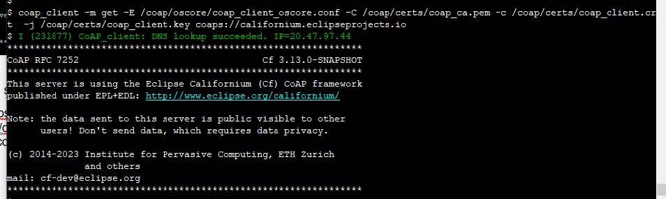
GET Request Based on PSK + OSCORE Security
coap_client -m get -E /coap/oscore/coap_client_oscore.conf -u password -k sesame coaps://californium.eclipseprojects.io
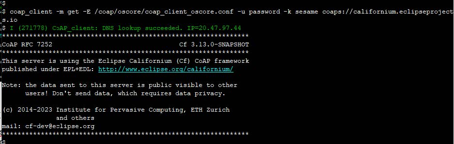
Upload Certificate File
Enable TLSR_FS CLI Tool
To configure the TLSR_FS CLI tool for uploading file:
Access the configuration menu:
-
Navigate to the configuration menu;
-
Select SDK;
-
Select include TLSR_FS CLI Tool.
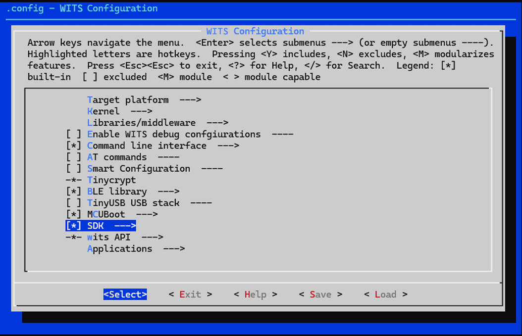
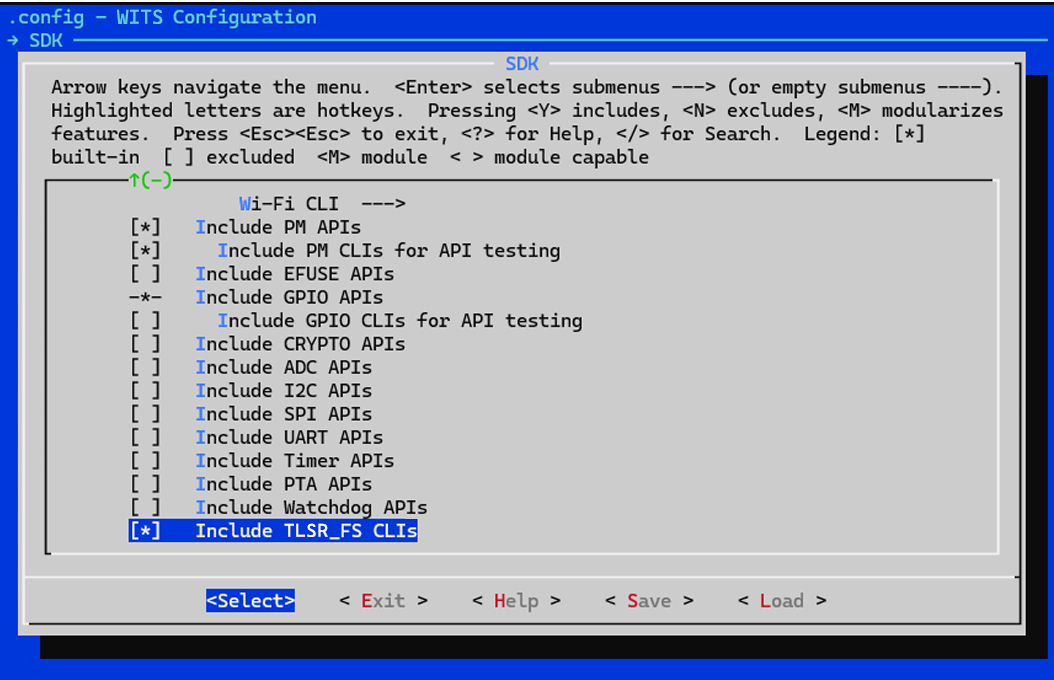
The TLSR_FS CLI tool supports several commands, including:
-
fs load: Upload file from the local computer via YMODEM. -
fs read: Read file content. -
fs write: Write data to file. -
fs rm: Delete file. -
fs size: Query file size.
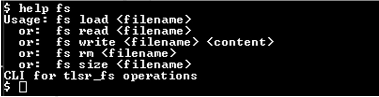
Upload Certificate File
For CoAP demo, the fs load command is used to upload certificate file. Follow the steps below to upload the file to WITS for demonstration:
Upload File
Use the fs load command and specify the filename where the uploaded file is saved.
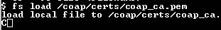
Select File
Select the file to be uploaded from YMODEM.
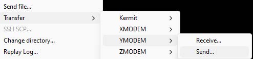
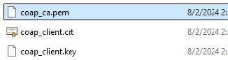
Read Uploaded File
Use the fs read command and the filename to read the content of the specified file.
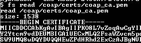
View Files in Directory
Use the ls command to view the file list in the current directory.

Note
- The
lscommand must be enabled in the configuration menu and included in the build as described above.
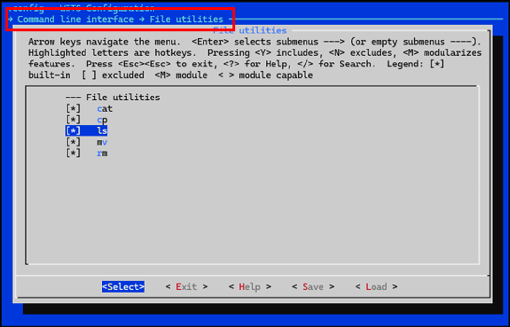
AT Command
Introduction
This section provides a comprehensive guide on how to use the TLSR9118 AT commands.
AT Command Type
The AT commands are used to control and interact with the TLSR9118. They are categorized into four types:
| Type | Command Format | Description |
|---|---|---|
| Test Command | AT+WL[interface]+<command name>=? | Query the internal parameters of the setup command and its allowed value ranges. [Interface] can be 0 or 1, representing different interfaces. |
| Query Command | AT+WL[interface]+<command name>? | Return the current value of specified parameter. |
| Setup Command | AT+WL[interface]+<command name>=<value> | Set the values of user-defined parameters in commands and then executes those commands. The value can be a string or an integer. |
| Execute Command | AT+WL[interface]+<command name> | Execute commands that do not require any user-defined parameters. |
Note
- Not all AT commands support all four types listed above.
- <command name> represents a specific AT command, e.g. CMUX, CFUN, etc.
- String parameters should be enclosed in double quotes. For example: AT+CMUX="Hello".
- The integer parameters must be within the allowable range specified by the corresponding test command.
- Angle bracket "< >" indicates required parameters that cannot be omitted.
Examples:
-
Test command: AT+WL0+CMUX=?
-
Query command: AT+WL1+CFUN?
-
Setup command: AT+WL0+CMUX="1,1"
-
Execute command: AT+WL1+CFUN=1
Basic AT Command
Overview
The TLSR9118 wireless Wi-Fi module can be controlled via the serial port using standard AT commands. This section provides a list of basic AT commands for implementing basic features.
| Command | Description |
|---|---|
| AT | Test AT startup |
| AT+RST | Reboot module |
| AT+GSLP | Go to sleep mode |
| ATE | Enable/disable AT command echo |
| AT+UART_CUR | Configure UART settings |
| AT+SLEEP | Set sleep mode |
| AT+SLEEPWKCFG | Configure wake-up source and GPIO |
Command
AT - Test AT Startup
Type: Execute;
Description: This command tests the basic communication and settings of the Wi-Fi module;
Command: AT;
Expected Response: OK;
Parameter: None.
AT+RST - Reboot Module
Type: Execute;
Description: This command reboots the Wi-Fi module;
Command: AT+RST;
Expected Response: OK;
Parameter: None.
AT+GSLP - Enter Deep Sleep Mode
Type: Setup;
Description: This command puts the module into deep sleep mode for specified time;
Command: AT+GSLP=<time>
Expected Response: <time> OK.
| Parameter | Description |
|---|---|
| <time> | Sleep duration, in milliseconds. A value of 0 means sleep indefinitely until awakened by an external source. Note: Modules may wake up earlier than the specified <time> due to other wake-up sources such as system timers. |
ATE - AT Command Echo
Type: Setup;
Description: This command enables or disables the echo of AT commands;
Command: ATE<value>;
Expected Response: OK;
Parameters:
<value>:
-
0: Disable echo;
-
1: Enable echo.
AT+UART_CUR - Current UART Communication Settings
Type: Setup;
Description: This command configures the current UART communication settings. Note that these settings are not persisted and do not override the default baud rate stored in flash memory;
Command: AT+UART_CUR=<baudrate>, <databits>, <stopbits>, <parity>, <flow control>;
Example: AT+UART_CUR=115200, 8, 1, 0, 3;
Expected Response: OK.
| Parameter | Description | Possible Value |
|---|---|---|
| <baudrate> | baudrate | Maximum 115200 |
| <databits> | databit | 5, 6, 7 or 8 |
| <stopbits> | stopbit | 1 (1 bit), 2 (1.5 bits), 3 (2 bits) |
| <parity> | parity check | 0 (none), 1 (odd parity), 2 (even parity) |
| <flow control> | flow control | 0 (disabled), 1 (RTS), 2 (CTS), 3 (RTS and CTS) |
Note
- These settingps are not saved to flash memory and will be lost after module reboot.
- The flow control feature requires hardware support.
AT+SLEEP - Sleep Mode
Type: Setup/Query;
Description: This command controls the sleep mode of the module. It is only applicable when the module is in workstation (STA) mode;
Query Command: AT+SLEEP?;
Query Response: +SLEEP: <sleep mode> OK;
Setup Command: AT+SLEEP=<sleep mode>;
Setup Response: OK;
Parameters:
<sleep mode>:
-
0: Disable sleep mode;
-
1: Light sleep mode;
-
2: Deep sleep mode;
-
3: Hibernation mode.
AT+SLEEPWKCFG - Configure Wake-Up Source
Type: Setup;
Description: This command configures the wake-up source and the GPIO pin responsible for waking up the module from sleep mode;
Command: AT+SLEEPWKCFG=<wakeup source>,<param1>,[<param2>];
Example: AT+SLEEPWKCFG=2,6;
Expected Response: OK.
| Parameter | Description |
|---|---|
| <wakeup source> | 0: Reserved (not supported); 1: Reserved (not supported). 2: GPIO. |
| <param1> | GPIO pin number (GPIO if <wakeup source> is set to 2). |
| <param2> (optional) | Wakeup level of GPIO pin (GPIO if <wakeup source> is set to 2). 0: low level trigger wakeup; 1: high level trigger wakeup. |
Wi-Fi Related AT Commands
Overview
This section describes the AT commands used to control and configure the TLSR9118 Wi-Fi feature. These commands begin with AT+WL0 or AT+WL1, where WL0 and WL1 refer to the two available Wi-Fi interfaces on the module. It is needed to replace WL0/1 with appropriate interface identifiers in the commands.
Command
AT+CWINIT - Initialize or Uninitialize Wi-Fi Driver
Type: Setup;
Description: This command initializes or uninitializes the Wi-Fi driver for specified interface;
Command: AT+WL0/1+CWINIT=<enable>;
Expected Response: OK.
Parameters:
<enable>: Enable or disable Wi-Fi driver.
-
1: Initialize the driver;
-
0: Uninitialize the driver.
AT+CWMAC - Wi-Fi MAC Address
Type: Setup/Query;
Description: This command sets or gets the MAC address of specified Wi-Fi interface;
Query Command: AT+ WL0/1+CWMAC?;
Query Response: +CWMAC: <MAC address> OK;
Setup Command: AT+ WL0/1+CWMAC=<MAC address>;
Set Response: OK.
| Parameter | Description | Example |
|---|---|---|
| <MAC address> | MAC address to be set (in the format XX:XX:XX:XX:XX:XX) | 64:f9:47:f0:03:38 |
AT+CWMODE - Wi-Fi Operating Mode
Type: Setup/Query;
Description: This command sets or gets the operating mode of specified Wi-Fi interface;
Test Command: AT+ WL0/1+CWMODE=?;
Test Response: +CWMODE: <mode> OK;
Query Command: AT+ WL0/1+CWMODE?;
Query Response: +CWMODE:<mode> OK;
Setup Command: AT+ WL0/1+CWMODE=<mode>;
Setup Response: OK.
Parameters:
<mode>: Wi-Fi operating mode.
-
1: Workstation mode (STA);
-
2: Soft Access Point mode (SoftAP).
AT+CWJAP - Access Point (AP) Configuration
Type: Setup/Query;
Description: This command sets or gets the configuration for connecting to an access point (AP) in workstation mode;
Example (Setup): AT+WL0+CWJAP=XH-Test 00000000 0 0 0;
Query Command: AT+ WL0+CWJAP?;
Query Response: +CWJAP:<ssid>,<bssid>,<channel>,<rssi>,<mode: 11n:0/1 11ax:0/1> OK;
Setup Command: AT+ WL0/1+CWJAP=<ssid> <pwd> <alg> <proto> <pmf>;
Setup Response: OK or ERROR.
| Parameter | Description | Possible Value/Indication |
|---|---|---|
| <ssid> | SSID of the target AP (string, enclosed in double quotes) | - |
| <pwd> | AP's password (string, enclosed in double quotes, up to 63 ASCII characters) | - |
| <alg> | Paired password type | 0: OPEN; 1: WEP; 2: TKIP; 3: CCMP; 6: SAE; 7: CCMP256 |
| <proto> | Encryption protocol | 0: OPEN; 1: WPA_PSK; 2: WPA2_PSK |
| <pmf> | Protected management frame | 0: PMF disabled; 1: PMF supported (preferred); 3: PMF required |
Note
- PMF (Protected Management Frame) enhances the security of management frame by preventing forgery and replay attack.
AT+CWCAP - Connecting to AP
Type: Execute;
Description: This command initiates the connection to AP based on the configuration previously set up using AT+CWJAP;
Command: AT+WL0+CWCAP;
Expected Response: OK.
AT+CWDHCP - Enable or Disable DHCP
Type: Setup/Query;
Description: This command enables or disables the DHCP client on specified Wi-Fi interface. When enabled, the device will automatically obtain IP address from DHCP server.
Query Command: AT+ WL0/1+CWDHCP?;
Query Response: +CWDHCP:<state> OK;
Setup Command: AT+ WL0/1+ CWDHCP =<operate>;
Setup Response: OK;
Parameters:
<operate>:
-
0: Disable DHCP;
-
1: Enable DHCP.
AT+CWSTR - Start Wi-Fi
Type: Execute;
Description: This command activates the Wi-Fi feature on specified interface;
Command: AT+ WL0/1+ CWSTR;
Expected Response: OK.
AT+CWSTOP - Stop Wi-Fi
Type: Execute;
Description: This command stops the Wi-Fi feature on specified interface;
Command: AT+ WL0/1+ CWSTOP;
Expected Response: OK.
AT+CWQAP - Disconnect from Current AP
Type: Execute;
Description: This command disconnects the workstation from the currently connected AP;
Command: AT+ WL0/1+ CWQAP;
Expected Response: OK.
AT+CWPWR - Query or Set the Maximum Transmit Power Limit
Type: Setup/Query;
Description: This command queries or sets the maximum transmit power limit for specified Wi-Fi interface;
Query Command: AT+ WL0/1+ CWPWR?;
Query Response: +CWPWR: max limited power = <power_value> OK;
Setup Command: AT+ WL0/1+ CWPWR=<pwr>;
Setup Response: OK;
Parameter: <pwr>: Maximum transmit power limit.
AT+CWPS - Query or Set Wi-Fi Power Saving Mode
Type: Setup/Query;
Description: This command queries or sets the power saving mode of specified Wi-Fi interface. The power saving mode can help reduce power consumption when the device is idle.
Query Command: AT+ WL0/1+ CWPS?;
Query Response: +CWPS:ps type = <WIFI_PS_NONE, WIFI_PS_MIN_MODEM, WIFI_PS_MAX_MODEM> OK;
Setup Command: AT+WL0/1+ CWPS=<mode>;
Setup Response: OK.
Parameters:
<mode>: Power saving mode.
-
0: WIFI_PS_NONE (no power saving);
-
1: WIFI_PS_MIN_MODEM (minimum power saving);
-
2: WIFI_PS_MAX_MODEM (maximum power saving).
AT+CWLAPOPT - Configure Behavior of AT+CWLAP Command
Type: Setup;
Description: This command configures the behavior of the AT+CWLAP command, which is used to scan for available access points (AP). It allows to control how the scan results are sorted and which parameters are displayed.
Example: AT+CWLAPOPT=1 511;
Command: AT+WL0/1+CWLAPOPT =<sort_enable>, <mask>;
Expected Response: OK or ERROR.
| Parameter | Description | Possible Value/Indication |
|---|---|---|
| <sort_enable> | Enable or disable sorting of scan results by RSSI | 0:not sorted by RSSI; 1:sorted by RSSI (descending order, highest signal strength at the top) |
| <mask> | A bit mask to control which parameters are displayed in the AT+CWLAP results | Each bit corresponds to a parameter (see table below). Set the bit to 1 to enable the display of the parameter, 0 to disable it. |
<mask> bitmask:
| bit | Parameter | Description |
|---|---|---|
| 0 | <encrypt> | Encryption status (e.g., open, WPA2) |
| 1 | <ssid> | SSID of the AP |
| 2 | <rssi> | Received Signal Strength Indicator (RSSI) |
| 3 | <bssid> | MAC address of AP |
| 4 | <ch> | AP's channel |
| 5 | <pairwits_cipher> | Paired password used by AP |
| 6 | <group_cipher> | Group password used by AP |
| 7 | <NGB> | Whether 802.11b/g/n is supported (1 if supported, 0 otherwise) |
| 8 | <WPS support> | Whether Wi-Fi Protected Setup (WPS) is supported |
AT+CWLAPN - Query the Number of Available Access Points (AP)
Type: Query;
Description: This command queries the number of available access points (AP) found during the last Wi-Fi scan.
Command: AT+WL0/1+ CWLAPN?;
Expected Response: +CWLAPN:ap_num=<number_of_aps> OK.
AT+CWSSCN - Stop Wi-Fi Scanning
Type: Execute;
Description: This command stops the ongoing Wi-Fi scan;
Command: AT+WL0/1+CWSSCN;
Expected Response: OK.
AT+CWLAP - Show Available Access Points (AP)
Type: Execute/Query;
Description: This command initiates a scan of available access points (AP) and optionally shows the results;
Examples:
-
AT+WL0+CWLAP: Scan all available AP on interface WL0.
-
AT+CWLAP?: Show the results of the last scan on interface WL1.
-
AT+CWLAP=ssid=MyNetwork ch=6: Scan AP with SSID "MyNetwork" on channel 6.
Query Command (Show Last Scan Result): AT+WL0/1+CWLAP?;
Query Response: +CWLAP:ap[i]=<ssid> <authmode> = b:0/1 g:0/1 n:0/1 ax:0/1 OK;
Execute Command (Start Scanning): AT+WL0/1+CWLAP;
Execute Response: OK;
Execute Command (Filtered Scan): AT+WL0/1+CWLAP=<ssid=> <bssid=> <ch=> <scantype=> <actmin=> <actmax=> <num=>;
Execute Response: OK.
| Parameter | Description | Possible Value/Indication |
|---|---|---|
| <ssid> | SSID of the AP to be searched (string, enclosed in double quotes) | - |
| <bssid> | MAC address of the AP to be searched | - |
| <ch> | Channel to be scanned | - |
| <scantype> | Type of scan to perform | `0`: active scanning; `1`: passive scanning. |
| <actmin> | Minimum active scan time per channel (milliseconds, range: 0-1500) | Valid only for active scanning. |
| <actmax> | Maximum active scan time per channel (milliseconds, range: 0-1500) | - |
| <num> | Maximum number of AP to show in the results | - |
AT+ CWLIF- Get IP and MAC
Type: Execute;
Description: This command retrieves the IP address and MAC address of the workstation currently connected to the SoftAP on specified interface;
Command: AT+CWLIF;
Expected Response: +CWLIF: <ip_address>,<mac_address> OK.
AT+ CWDHCPS- Query or Configure IPv4 Address Range
Type: Setup/Query;
Description: This command queries or configures the range of IPv4 address that the DHCP server on the SoftAP assigns to connected clients.
Query Command: AT+WL0/1+CWDHCPS?;
Query Response: +CWDHCPS: <lease_time>,<start_ip>,<end_ip> OK;
Setup Command: AT+WL0/1+CWDHCPS=<enable>,<lease_time>,<start_ip>,<end_ip>;
Setup response: OK.
| Parameter | Description | Illustration |
|---|---|---|
| <enable> | Enable or disable DHCP server | 1: Enable DHCP server and configure the address range; 0: Disable DHCP server and use default address range. |
| <lease_time> | DHCP lease time (minutes) | Range: 1-2880 |
| <start_ip> | Starting IPv4 address for DHCP range | - |
| <end_ip> | Ending IPv4 address for DHCP range | - |
AT+ CWSAP- Query or Configure SoftAP Settings
Type: Setup/Query;
Description: This command queries or configures the settings of SoftAP on specified interface;
Query Command: AT+WL0/1+CWSAP?;
Query Response: +CWSAP: <ssid>,<pwd>,<channel>,<ecn>,<proto>,<max_conn>,<ssid_hidden> OK;
Setup Command: AT+WL0/1+CWSAP=<ssid>,<pwd>,<chl>,<ecn>,<proto>,[<max_conn>],[<ssid_hidden>];
Setup Response: OK.
| Parameter | Description | Possible Value/Indication |
|---|---|---|
| <ssid> | SSID of SoftAP (string, enclosed in double quotes) | - |
| <pwd> | Password of SoftAP (string, enclosed in double quotes, 8-63 ASCII characters) | - |
| <chl> | SoftAP's channel | - |
| <ecn> | Encryption method | 0: OPEN; 3: CCMP (WEP and TKIP not supported) |
| <proto> | Security protocol | 0: NONE; 2: WPA2 (WPA2 only) |
| [<max_conn>] | Maximum number of workstations that can be connected to SoftAP | Optional Parameter |
| [<ssid_hidden>] | Control whether to broadcast SSID | 0: Broadcast SSID (default); 1: Hide SSID. |
AT+ CWCOUNTRY- Query or Set Wi-Fi Country/Region Code
Type: Setup/Query;
Description: This command queries or sets the Wi-Fi country/region code for specified interface. The country/region code affects the available channel and regulatory domain for Wi-Fi operation.
Query Command: AT+WL0/1+CWCOUNTRY?;
Query Response: Country: <country_code>,<total_channel_count> OK;
Setup Command: AT+WL0/1+CWCOUNTRY=<country_code>;
Setup Response: OK.
| Parameter | Description | Illustration |
|---|---|---|
| <country_code> | Two letter ISO 3166-1 alpha-2 country/region code (e.g., "US" for United States) | - |
| <total_channel_count> | Total number of Wi-Fi channels available in specified country/region | This value is returned by the query command. |
Example
This section provides some practical examples of how to perform common tasks using Wi-Fi related AT commands.
Connect to AP and Obtain IP Address via DHCP
This example demonstrates how to connect to an access point (AP) and then use DHCP to obtain IP address automatically.
AT+WL0+CWINIT=1//Initialize the Wi-Fi driver on interface WL0

OK
AT+WL0+CWMODE=1//Set Wi-Fi mode to workstation (STA)

OK
AT+WL0+CWJAP=HUAWEI-Test 00000000 0 0 0//Connect to AP "HUAWEI-Test" (open network)

OK
AT+WL0+CWCAP//Initiate connection

OK

WIFI CONNECTED //(Unsolicited response, indicating a successful connection)
AT+WL0+CWDHCP=1 //Enable DHCP client

OK

WIFI GOT IP //(Unsolicited response, indicating that an IP address has been acquired)
Scan Available AP and Show Result
This example demonstrates how to scan for available AP and then shows the result.
AT+WL0+CWINIT=1 // Initialize the Wi-Fi driver

OK
AT+WL0+CWMODE=1 //Set Wi-Fi mode to Workstation (STA)

OK
AT+WL0+CWLAP //Initiate Wi-Fi scanning

OK
AT+WL0+CWLAP? //Show scan result
+CWLAP:ap[0] = SC-Ent authmode = 7 b:1 g:1 n:1 ax:0
+CWLAP:ap[1] = SC-IoT authmode = 6 b:1 g:1 n:1 ax:0
+CWLAP:ap[2] = SC-Guest authmode = 6 b:1 g:1 n:1 ax:0
+CWLAP:ap[3] = NFC authmode = 6 b:1 g:1 n:1 ax:1
+CWLAP:ap[4] = apache_test authmode = 3 b:1 g:1 n:1 ax:1
+CWLAP:ap[5] = CMCC-AP2 authmode = 3 b:1 g:1 n:1 ax:1
+CWLAP:ap[6] = RT-BE88U-MLO authmode = 8 b:1 g:1 n:1 ax:1
+CWLAP:ap[7] = CMCC-CQpy authmode = 3 b:1 g:1 n:1 ax:1
+CWLAP:ap[8] = CMCC-CQpy-3 authmode = 3 b:1 g:1 n:1 ax:1
+CWLAP:ap[9] = SC-Ent authmode = 7 b:1 g:1 n:1 ax:0
+CWLAP:ap[10] = SC-Guest authmode = 6 b:1 g:1 n:1 ax:0
+CWLAP:ap[11] = SC-IoT authmode = 6 b:1 g:1 n:1 ax:0
+CWLAP:ap[12] = SC-IoT authmode = 6 b:1 g:1 n:1 ax:0
+CWLAP:ap[13] = DIRECT-E3MROOM4msUN authmode = 3 b:0 g:1 n:1 ax:1
+CWLAP:ap[14] = SC-Ent authmode = 7 b:1 g:1 n:1 ax:0
+CWLAP:ap[15] = SC-IoT authmode = 6 b:1 g:1 n:1 ax:0
+CWLAP:ap[16] = wULu63h authmode = 3 b:1 g:1 n:1 ax:0
+CWLAP:ap[17] = TP-LINK_3A1D_2G authmode = 0 b:1 g:1 n:1 ax:1
+CWLAP:ap[18] = HUAWEI-Test authmode = 0 b:1 g:1 n:1 ax:1
+CWLAP:ap[19] = Xiaomi_7AB6 authmode = 0 b:1 g:1 n:1 ax:1
+CWLAP:ap[20] = SWaJrIdwhRkTT4e1nu authmode = 0 b:1 g:1 n:1 ax:1
+CWLAP:ap[21] = letter_sap authmode = 0 b:1 g:1 n:1 ax:1
+CWLAP:ap[22] = xiaohu_test authmode = 0 b:1 g:1 n:1 ax:0
+CWLAP:ap[23] = 3333h authmode = 0 b:1 g:1 n:1 ax:0 OK
Note
- The format of the +CWLAP response may vary depending on the configuration of the AT+CWLAPOPT setting.
Start SoftAP and Configure DHCP Server
This example demonstrates how to configure and start SoftAP and then set up a DHCP server to assign IP address to connected clients.
AT+CWINIT=1 // Initialize the Wi-Fi driver
OK

AT+WL1+CWMODE=2 // Set Wi-Fi mode to SoftAP on interface WL1

OK

AT+WL1+CWDHCPS=1,1,"192.168.66.2","192.168.66.10" // Enable DHCP server and configure IP address range

OK

AT+WL1+CWSAP="telink_test",12345678,6,3,2 // Configure SoftAP settings (SSID, password, etc.)

OK

AT+WL1+CWDHCPS? // Query DHCP server configuration (optional)

+CWDHCPS:1,"192.168.66.2","192.168.66.10"
TCP/IP AT Commands
Overview
This section describes the AT commands used to control and configure the TLSR9118 module's TCP/IP network functions. These commands allow to establish TCP and UDP connections, send and receive data, manage the network interface, and perform network diagnostics.
Command
AT+CIFSR - Get local IP Address and MAC Address
Type: Execute;
Description: This command retrieves the local IP address (IPv4 and IPv6) and MAC address of the workstation (STA) and soft AP (AP) interfaces;
Command: AT+CIFSR;
Expected Response:
-
+CIFSR:STAIP,"<STA_IPv4_address>"
-
+CIFSR:STAMAC,"<STA_MAC_address>"
-
+CIFSR:STAIP6LL,"<STA_IPv6_link-local_address>"
-
+CIFSR:STAIP6GL,"<STA_IPv6_global_address>"
-
+CIFSR:APIP,"<AP_IPv4_address>" OK.
Note
- The IPv6 support must be enabled in the module configuration (for example, by enabling the LWIP_IPV6 kconfig option) in order to show IPv6 address.
AT+CIPSTA - Query/Set IP Address of Workstation
Type: Setup/Query;
Description: This command queries or sets the IPv4 address, gateway and subnet mask of the workstation (STA) interface, it also queries the IPv6 link-local and global addresses;
Query Command: AT+CIPSTA?;
Query Response:
-
+CIPSTA:ip,"<STA_IPv4_address>"
-
+CIPSTA:gateway,"<gateway_address>"
-
+CIPSTA:netmask,"<netmask>"
-
+CIPSTA:ip6ll,"<STA_IPv6_link-local_address>"
-
+CIPSTA:ip6gl,"<STA_IPv6_global_address>" OK.
Setup Command: AT+CIPSTA="<IPv4_address>",[,"<gateway_address>","<netmask>"];
Setup Response: OK.
| Parameter | Description |
|---|---|
| <IPv4_address> | IPv4 address to be assigned to STA interface (string, enclosed in double quotes) |
| <gateway_address> | Gateway address (optional, string, enclosed in double quotes) |
| <netmask> | Subnet mask (optional, string, enclosed in double quotes) |
Note
- This command cannot set IPv6 address.
AT+CIPSTAMAC - Query/Set Workstation MAC Address
Type: Setup/Query;
Description: This command queries or sets the MAC address of the workstation (STA) interface;
Query Command: AT+CIPSTAMAC?;
Query Response: +CIPSTAMAC: "<mac_address>" OK;
Setup Command: AT+CIPSTAMAC=<mac_address>;
Setup Response: OK.
| Parameter | Description | Example |
|---|---|---|
| <mac_address> | MAC address to be assigned to the STA interface (string, enclosed in double quotes) | 64:f9:47:f0:03:38 |
AT+CIPAP - Query/Set the IP Address of the Soft AP
Type: Setup/Query;
Description: This command queries or sets the IPv4 address, gateway and subnet mask of the soft AP (AP) interface;
Query Command: AT+CIPAP?;
Query Response:
-
+CIPAP:ip,"<AP_IPv4_address>"
-
+CIPAP:gateway,"<gateway_address>"
-
+CIPAP:netmask,"<netmask>" OK;
Setup Command: AT+CIPAP="<IPv4_address>",[,"<gateway_address>","<netmask>"];
Setup Response: OK.
| Parameter | Description |
|---|---|
| <IPv4_address> | IPv4 address to be assigned to the AP interface (string, enclosed in double quotes) |
| <gateway_address> | Gateway address (optional, string, enclosed in double quotes) |
| <netmask> | Subnet mask (optional, string, enclosed in double quotes) |
AT+CIPAPMAC - Query/Set the MAC Address of the Soft AP
Type: Setup/Query;
Description: This command queries or sets the MAC address of the soft AP (AP) interface;
Query Command: AT+CIPAPMAC?;
Query Response: +CIPAPMAC: "<mac_address>" OK;
Setup Command: AT+CIPAPMAC=<mac_address>;
Setup Response: OK.
| Parameter | Description | Example |
|---|---|---|
| <mac_address> | MAC address to be assigned to the AP interface (string, enclosed in double quotes) | 64:f9:47:f0:03:39 |
AT+PING - Ping Remote Host
Type: Execute;
Description: This command sends an ICMP echo request (ping) to a remote host to test network connectivity;
Command: AT+PING=<host>;
Examples:
-
AT+PING="192.168.1.1"
-
AT+PING="www.baidu.com"
Expected Response (Success): +PING: <time_in_milliseconds> OK;
Expected Response (Timeout): +PING:TIMEOUT ERROR
| Parameter | Description |
|---|---|
| <host> | IP address (IPv4 or IPv6) or domain name (string, enclosed in double quotes) of the remote host |
Note
- The IPv6 support must be enabled in the module configuration to ping IPv6 address.
AT+CIPSTART - Establish TCP Connection, UDP Transmission, or SSL Connection
Type: Execute;
Description: This command establishes TCP, UDP or SSL connection with a remote host;
TCP/SSL Connection Command: AT+CIPSTART=<link_ID>,<type>,<remote_host>,<remote_port>[,<keep_alive>];
Examples of TCP/SSL connection:
-
AT+CIPSTART=1, TCP, 192.168.3.98, 9001
-
AT+CIPSTART=4, SSL, 192.168.3.98, 9002
TCP/SSL Connection Expected Response: link id: <link_ID>, CONNECT OK;
UDP Connection Command: AT+CIPSTART=<link_ID>,<type>,<remote_host>,<remote_port>,<local_port>;
UDP Connection Example: AT+CIPSTART=3, "UDP", "192.168.3.98",8080,1113;
UDP Connection Expected Response:
-
Local port: <local_port>
-
Link id: <link_ID>, CONNECT OK.
| Parameter | Description | Possible Value/Indication |
|---|---|---|
| <link_ID> | Integer (0-4) of the connection ID. | - |
| <type> | Connection type | "TCP"、"UDP" or "SSL" |
| <remote_host> | IP address (IPv4 or IPv6) or domain name (string, enclosed in double quotes) of the remote host | Maximum length: 64 bytes |
| <remote_port> | Port number of the remote host | - |
| <keep_alive> (TCP/SSL only) | Enable or disable TCP keep-alive connection | 0: Disable keep-alive connection (default). 1-7200: Enable keep-alive connection for the specified interval (in seconds). |
| <local_port> (UDP only) | Local UDP port to be used | - |
Note
- The IPv6 support must be enabled in the module configuration to connect to an IPv6 address.
AT+CIPSTATUS - Get TCP/UDP/SSL Connection Status and Information
Type: Execute;
Description: This command retrieves the status and information of active TCP, UDP, and SSL connections;
Command: AT+CIPSTATUS;
Expected Response: +CIPSTATUS. <link_ID>,<type>,<remote_host>,<remote_port>,<local_port>,<status> OK.
| Parameter | Description | Possible Value/Indication |
|---|---|---|
| <link_ID> | Connection ID | - |
| <type> | Connection type | "TCP", "UDP" or "SSL" |
| <remote_host> | IP address or domain name of the remote host | - |
| <remote_port> | Remote port number | - |
| <local_port> | Local port number (for UDP connection) | - |
| <server> | Connection status | - |
AT+CIPSEND - Send Data in Normal Transmission Mode or Wi-Fi Transparent Transmission Mode
Type: Execute;
Description: This command sends data over an established TCP, UDP or SSL connection, which supports two modes: normal transmission mode and Wi-Fi transparent transmission mode;
Normal Transmission Mode Command: AT+CIPSEND=<link_ID>,<length>;
Expected Response for Normal Transmission Mode: OK;
Wi-Fi Transparent Transmission Mode Command: AT+CIPSEND=<link_ID>;
Wi-Fi Transparent Transmission Mode Expected Response: OK;
Error Response (If Connection is Not Valid): Link is not valid ERROR;
| Parameter | Description | Illustration |
|---|---|---|
| <link_ID> | Connection ID | - |
| <length> (Normal mode only) | Length of data to be sent (in bytes) | Maximum value: 2048 bytes (defined by CONFIG_AT_ CIPSEND_MAX) |
Normal Transmission Mode: In this mode, send data after receiving the > prompt. The module then transmits the data over the specified connection.
Wi-Fi Transparent Transmission mode: In this mode, all data received after the > prompt on the serial port are transmitted directly through the specified connection without any processing by the module. Exit the transparent transmission mode by sending the special command +++ (followed by a carriage return).
AT+CIPINFO - Set "+IPD" Message Mode
Type: Setup/Query;
Description: This command enables or disables the display of detailed remote host information in the +IPD unsolicited response that indicates incoming data on a TCP or UDP connection;
Setup Command: AT+CIPINFO=<mode>;
Setup Response: OK;
Query Command: AT+CIPINFO?;
Query Response (Enabled): +CIPINFO:TRUE OK;
Query Response (Disabled): +CIPINFO:FALSE OK.
Parameters:
<mode>: Enable or disable detailed +IPD information.
-
0: Disable;
-
1: Enable.
AT+CIPCLOSE - Close TCP/UDP/SSL Connection
Type: Execute;
Description: This command closes active TCP, UDP or SSL connections.
Command: AT+CIPCLOSE=<link_ID>;
Expected Response (Success): OK or <link_ID>,CLOSE OK;
Error Response: UNLINK ERROR;
Parameter: <link_ID>, ID of the connection to be closed.
Power Management AT Commands
Overview
This section describes the AT commands related to power management (PM) on the TLSR9118 module. These commands allow to control system power management and Wi-Fi power saving features to optimize power consumption.
| Command | Description |
|---|---|
| AT+PME | Enable/disable system power management |
| AT+PMEW | Enable/disable WLAN power saving |
Command
AT+PME - Enable/Disable System Power Management
Type: Setup;
Description: This command enables or disables the system power management feature of the TLSR9118 module;
Command: AT+PME=<enable>;
Expected response: OK.
Parameters:
<enable>: Enable or disable system power management.
-
0: Disable system power management;
-
1: Enable system power management.
Note
- Enabling system power management may put the module into a low-power state at idle, which may affect responsiveness.
AT - Test AT Startup
Type: Setup;
Description: This command enables or disables the power saving mode of the Wi-Fi (WLAN) interface; When enabled, the Wi-Fi interface goes into a low-power state during periods of inactivity to save power;
Command: AT+PMEW=<enable>[,<interval>];
Expected Response: OK.
| Parameter | Description | Possible Value/Indication |
|---|---|---|
| <enable> | Enable or disable WLAN power saving | 0: Disable WLAN power saving; 1: Enable WLAN power saving. |
| <interval> | Time interval (in milliseconds) between wakeup cycles for beacon listening (optional) | Range: 100-1000 (default: 100) |
Note
- The <interval> parameter specifies the frequency at which the Wi-Fi interface wakes up to listen for beacons from the access point (AP). A shorter interval improves response speed but consumes more power.
Debugging Guide
Overview
The Debugging Guide provides basic debugging techniques for common problems encountered during application development. It can be used as both a teaching tool and a quick reference for troubleshooting.
Coverage
This document focuses on solving the following specific types of problems:
- Core Exception
- Assertion Failure
- Stack Overflow
- Memory Leak
In addition, other issues such as deadlocks may arise; however, the strategies and tools discussed in this document are equally applicable to these scenarios. For in-depth debugging, it is recommended to use a JTAG debugger like AICE-MICRO with OpenOCD. Detailed setup instructions can be found in the SDK Getting Started Guide.
Logging Mechanism
The TLSR9118 SDK provides two primary methods for logging via the UART console:
| Function | Header File | Description |
|---|---|---|
| int Incl printf (const char *format, ...) |
ude/stdio.h - Se - No | nd byte string directly to UART port. t suitable for use in ISR contexts, as it relies on OS-related wait functions. - Introduce significant runtime overhead. - Not included in the core dump, refer to section Using the ps command. |
| int Incl printk (const char *format, ...) |
ude/hal/console.h - Ou - Ca | tput byte string to a configurable internal console buffer. n be used in threaded and ISR contexts. - The dmesg CLI command displays the entire console buffer; subsequent call clears the buffer. - dmesg start enables real-time logging with minimal performance impact. - Included in the core dump, refer to section Using the ps command. |
For effective troubleshooting, use printf or printk to quickly seperate the problem, thereby reducing the time and effort of subsequent steps.
Use ps Command
The ps command provides insight into the system's active tasks, helping to identify potential problems related to task management and resource utilization.
Command output:
$ ps
PID  PR  STWM  S  %CPU+  TIME+    TASK
  1  3   480   X  2.3    0:00:01  init                          (0x21bda0-0x21cd90, 0x21c85c)
  2  0   966   R  78.7   0:00:45  idle                          (0x20fc04-0x210c00, 0x210b1c)
  3  5   199   B  18.9   0:00:10  ksofttimerd                   (0x20f780-0x20fb70, 0x20fa9c)
  4  3   683   B  0.0    0:00:00  knetd                         (0x21d0b0-0x21dca0, 0x21db5c)
  5  3   571   B  0.0    0:00:00  tlsr_wlan-wlan fast taskq     (0x21f710-0x220100, 0x21fffc)
  7  3   303   B  0.0    0:00:00  rt_msg                        (0x221600-0x221bf0, 0x221acc)
  6  3   315   B  0.0    0:00:00  knet80211d/wlan0              (0x220d30-0x221320, 0x22121c)
  8  7   48    B  0.0    0:00:00  ll                            (0x2222e0-0x222550, 0x22244c)
$
The ps command shows the information described in the following table.
| Listing | Meaning | Description |
|---|---|---|
| PID | Process Identifier | Assigned by the operating system. |
| PR | Priority | Refer to CMSIS-FreeRTOS_API guide. |
| STWM | STWM (Stack Watermark) | Indicate the minimum observed free stack space. |
| S | Task Status | 'X': Running 'R': Ready 'B': Blocking 'S': Suspend 'D': Delete 'I': Invalid |
| %CPU+ | Relative CPU utilization | Percentage of CPU utilization (relative) |
| TIME+ | Absolute CPU time consumed by task | CPU utilization time (absolute) |
| TASK | Task Name | Specify at creation |
| Stack | (Start-End, sp) | See below. |
This information provides a snapshot of the current system status and helps to diagnose problems effectively.
The three hexadecimal numbers in parentheses indicate the start address, end address, and last recorded stack pointer of the task stack, respectively.
For example, the stack for the 'init' task is located between 0x21bda0 and 0x21cd90, and the last recorded stack pointer is 0x21c85c.
The 'STWM' (Stack Watermark) column reflects the minimum free space (in uint32) available to the task during its most resource-intensive operations. Lower values in this column indicate a higher risk of stack overflow.
"The last recorded stack pointer" refers to the value of the stack pointer that is saved by the operating system (FreeRTOS in this case) during context switches, such as between tasks or when switching from a task to an interrupt. The ps command shows this value, providing insight into each task's stack usage pattern.
Although "The last recorded stack pointer" does not provide a real-time stack pointer value, especially for currently running tasks, it is very useful in debugging. Analyzing the memory contents of the last known status of the stack can reveal critical information about the status of the task before a switch or error occurs.
To further understand the stack status of the 'init' task at the last context switch, we can examine the memory as follows:
$ hexdump 0x21c85c 64
0x0021c850: .... .... .... .... .... .... 4ac7 1000 ............J
0x0021c860: 4000 0000 0000 0000 a5a5 a5a5 0ec8 1000 @
0x0021c870: a500 0000 a0bd 2100 90cd 2100 f02c 2200        ! ! ,"
0x0021c880: 2800 0000 0000 0000 708e 0980 0800 0000 (      p
0x0021c890: d000 0000 0000 0000 082e 2200 .... ....        ." ....
$
Note that the hexdump command shows the memory contents in bytes, maintaining byte order. In contrast, the read command shows data in words, each word consisting of 32 bits. This format is particularly helpful in understanding the structure the system processes the data.
The sample output of the read command is as follows:
$ read 0x21c85c 16
[0x21c85c] 0x0010c74a
[0x21c860] 0x00000040
[0x21c864] 0x00000000
[0x21c868] 0xa5a5a5a5
[0x21c86c] 0x0010c80e
[0x21c870] 0x000000a5
[0x21c874] 0x0021bda0
[0x21c878] 0x0021cd90
[0x21c87c] 0x00222cf0
[0x21c880] 0x00000028
[0x21c884] 0x00000000
[0x21c888] 0x80098e70
[0x21c88c] 0x00000008
[0x21c890] 0x000000d0
[0x21c894] 0x00000000
[0x21c898] 0x00222e08
$
This output provides a clear view of the data structure in memory at a particular address, which is essential for debugging and tracing problems in the system.
Understanding how to derive the call flow from a stack dump involves analyzing such memory contents to retrace the function call that led to the current status, a procedure which will be detailed later in this document. This analysis helps to identify the sequence of events or errors that led to the exception or crash, thus helping to pinpoint the root cause of the problem.
Core Dump
A core dump is automatically generated when a trap exception occurs or an assertion fails. It provides a detailed snapshot of the memory and processor status at the time of the exception, which is critical for debugging. The core dump is output directly to the UART console, allowing developers to analyze the conditions that led to the failure.
Core dump example:
WITS 2018.02+ riscv32-elf-gcc.gnu (2022-02-07_nds32le-elf-mculib-v5-86807094a2f) 10.3.0
[000361.560214] BOARD: tlsr_w91 QFN40 EVB V1.0
[000361.560368] VFS: filesystem devfs mounted onto /dev
[000361.562230] PINCTRL: pin controller tlsr_w91,pinctrl registered
[000361.562440] GPIO: tlsr_w91,pinctrl registered as /dev/gpio
[000361.562728] atcwdt: @0xf1300000, clk=32768
[000361.562936] WDT: atcwdt registered as /dev/watchdog
[000361.563279] PINCTRL: atcspi200-xip/cs request pin 11
[000361.563471] PINCTRL: atcspi200-xip/clk request pin 12
[000361.563636] PINCTRL: atcspi200-xip/mosi request pin 13
[000361.563808] PINCTRL: atcspi200-xip/miso request pin 14
[000361.563993] PINCTRL: atcspi200-xip/hold request pin 9
[000361.564173] PINCTRL: atcspi200-xip/wp request pin 10
[000361.564667] EFUSE: efuse-tlsr_w91 registered as /dev/efuse
[000361.564799] trng version : 5e5e0010
[000361.564962] TRNG: trng registered as /dev/trng
[000361.565084] pke version : 0x5e5e0010
[000361.607174] Use fixed MAC address: 64.f9.47.f0.01.20
[000361.608169] 261 usec elapsed in downloading MAC FW.
[000362.902695] Wlan PM ctx init done
[000362.904031] UART: atcuart.0 registered as /dev/ttyS0
[000362.904346] CONSOLE: add /dev/ttyS0
[000362.904664] UART: atcuart.1 registered as /dev/ttyS1
[000362.904788] SOC: tlsr_w91
[000362.905306] Use fixed BLE public address: 01.02.03.04.05.06
[000362.907563] ble phy init 35
[000362.907711] PM feature : 0x1d
[000362.908487] PM LS : 6500+1120=7620
[000362.908655] PM SL : 6500+7100=13600
[000362.908817] PM DS : 11500+12800=24300
[000362.908990] PM HB : 1655000+60000=1715000
[000362.909248] PINCTRL: atcuart.0/txd request pin 22
[000362.909412] PINCTRL: atcuart.0/rxd request pin 21
[000377.371510] Unhandled Trap : Ilegal instruction (mcause = 0x2), mepc = 0xc0000000
[000377.379216] EPC:c0000000
[000377.381940] MSTATUS:00001880
[000377.385019] MXSTATUS:00000080
[000377.388188] MTVAL:00003003
[000377.391092] A0:c0000000 A1:00000000 A2:00000010 A3:00000001 A4:00000002 A5:ffffffff A6:00000008 A7:00210f37
[000377.401165] T0:8008e6f8 T1:001096f0 T2:00000000 T3:00210f2c T4:000001b0 T5:8008e71c T6:00000008
[000377.410197] S0:00000002 S1:0020d488 S2:ffffffff S3:00000001 S4:8010a220 S5:a5a5a5a5 S6:a5a5a5a5 S7:a5a5a5a5
[000377.420373] S8:a5a5a5a5 S9:a5a5a5a5 S10:a5a5a5a5 S11:a5a5a5a5
[000377.426377] FP:00000002 RA:8008e6fe
[000377.429989] sp: 0021cb6c
[000377.432977] IRQ stack:
[000377.435443] base: 0021b590
[000377.438433] size: 00000800
[000377.441429] ERROR: Stack pointer is not within the interrupt stack
[000377.447766] 0021b580: 00000000 00000000 00000000 00000000 00000000 00000000 00000000 00000000
[000377.456531] 0021b5a0: 00000000 00000000 00000000 00000000 00000000 00000000 00000000 00000000
[000377.465294] 0021b5c0: 00000000 00000000 00000000 00000000 00000000 00000000 00000000 00000000
[000377.474056] 0021b5e0: 00000000 00000000 00000000 00000000 00000000 00000000 00000000 00000000
[000377.482819] 0021b600: 00000000 00000000 00000000 00000000 00000000 00000000 00000000 00000000
[000377.491582] 0021b620: 00000000 00000000 00000000 00000000 00000000 00000000 00000000 00000000
[000377.500345] 0021b640: 00000000 00000000 00000000 00000000 00000000 00000000 00000000 00000000
[000377.509108] 0021b660: 00000000 00000000 00000000 00000000 00000000 00000000 00000000 00000000
[000377.517871] 0021b680: 00000000 00000000 00000000 00000000 00000000 00000000 00000000 00000000
[000377.526634] 0021b6a0: 00000000 00000000 00000000 00000000 00000000 00000000 00000000 00000000
[000377.535397] 0021b6c0: 00000000 00000000 00000000 00000000 00000000 00000000 00000000 00000000
[000377.544160] 0021b6e0: 00000000 00000000 00000000 00000000 00000000 00000000 00000000 00000000
[000377.552923] 0021b700: 00000000 00000000 00000000 00000000 00000000 00000000 00000000 00000000
[000377.561686] 0021b720: 00000000 00000000 00000000 00000000 00000000 00000000 00000000 00000000
[000377.570448] 0021b740: 00000000 00000000 00000000 00000000 00000000 00000000 00000000 00000000
[000377.579211] 0021b760: 00000000 00000000 00000000 00000000 00000000 00000000 00000000 00000000
[000377.587974] 0021b780: 00000000 00000000 00000000 00000000 00000000 00000000 00000000 00000000
[000377.596737] 0021b7a0: 00000000 00000000 00000000 00000000 00000000 00000000 00000000 00000000
[000377.605500] 0021b7c0: 00000000 00000000 00000000 00000000 00000000 00000000 00000000 00000000
[000377.614263] 0021b7e0: 00000000 00000000 00000000 00000000 00000000 00000000 00000000 00000000
[000377.623026] 0021b800: 00000000 00000000 00000000 00000000 00000000 00000000 00000000 00000000
[000377.631789] 0021b820: 00000000 00000000 00000000 00000000 00000000 00000000 00000000 00000000
[000377.640551] 0021b840: 00000000 00000000 00000000 00000000 00000000 00000000 00000000 00000000
[000377.649314] 0021b860: 00000000 00000000 00000000 00000000 00000000 00000000 00000000 00000000
[000377.658077] 0021b880: 00000000 00000000 00000000 00000000 00000000 00000000 00000000 00000000
[000377.666840] 0021b8a0: 00000000 00000000 00000000 00000000 00000000 00000000 00000000 00000000
[000377.675603] 0021b8c0: 00000000 00000000 00000000 00000000 00000000 00000000 00000000 00000000
[000377.684366] 0021b8e0: 00000000 00000000 00000000 00000000 00000000 00000000 00000000 00000000
[000377.693129] 0021b900: 00000000 00000000 00000000 00000000 00000000 00000000 00000000 00000000
[000377.701892] 0021b920: 00000000 00000000 00000000 00000000 00000000 00000000 00000000 00000000
[000377.710655] 0021b940: 00000000 00000000 00000000 00000000 00000000 00000000 00000000 00000000
[000377.719417] 0021b960: 00000000 00000000 00000000 00000000 00000000 00000000 00000000 00000000
[000377.728180] 0021b980: 00000000 00000000 00000000 00000000 00000000 00000000 00000000 00000000
[000377.736943] 0021b9a0: 00000000 00000000 00000000 00000000 00000000 00000000 00000000 00000000
[000377.745706] 0021b9c0: 00000000 00000000 00000000 00000000 00000000 00000000 00000000 00000000
[000377.754469] 0021b9e0: 00000000 00000000 00000000 00000000 00000000 00000000 00000000 00000000
[000377.763231] 0021ba00: 00000000 00000000 00000000 00000000 00000000 00000000 00000000 00000000
[000377.771994] 0021ba20: 00000000 00000000 00000000 00000000 00000000 00000000 00000000 00000000
[000377.780757] 0021ba40: 00000000 00000000 00000000 00000000 00000000 00000000 00000000 00000000
[000377.789520] 0021ba60: 00000000 00000000 00000000 00000000 00000000 00000000 00000000 00000000
[000377.798283] 0021ba80: 00000000 00000000 00000000 00000000 00000000 00000000 00000000 00000000
[000377.807046] 0021baa0: 00000000 00000000 00000000 00000000 00000000 00000000 00000000 00000000
[000377.815809] 0021bac0: 00000000 00000000 00000000 00000000 00000000 00000000 00000000 00000000
[000377.824572] 0021bae0: 00000000 00000000 00000000 00000000 00000000 00000000 00000000 00000000
[000377.833334] 0021bb00: 00000000 00000000 00000000 00000000 00000000 00000000 00000000 00000000
[000377.842097] 0021bb20: 00000000 00000000 00000000 00000000 00000000 00000000 00000000 00000000
[000377.850860] 0021bb40: 00000000 00000000 00000000 00000000 00000000 00000000 00000000 00000000
[000377.859623] 0021bb60: 00000000 00000000 00000000 00000000 00000000 00000000 00000000 00000000
[000377.868386] 0021bb80: 00000000 00000000 00000000 00000000 00000000 00000000 00000000 00000000
[000377.877149] 0021bba0: 00000000 00000000 00000000 00000000 00000000 00000000 00000000 00000000
[000377.885911] 0021bbc0: 00000000 00000000 00000000 00000000 00000000 00000000 00000000 00000000
[000377.894674] 0021bbe0: 00000000 00000000 00000000 00000000 00000000 00000000 00000000 00000000
[000377.903437] 0021bc00: 00000000 00000000 00000000 00000000 00000000 00000000 00000000 00000000
[000377.912200] 0021bc20: 00000000 00000000 00000000 00000000 00000000 00000000 00000000 00000000
[000377.920963] 0021bc40: 00000000 00000000 00000000 00000000 00000000 00000000 00000000 00000000
[000377.929726] 0021bc60: 00000000 00000000 00000000 00000000 0020c310 00203bf4 0020c9b8 80100c3a
[000377.938604] 0021bc80: 0020c310 00203bf4 0020c9b8 00000000 a5a5a5a5 a5a5a5a5 a5a5a5a5 0021bd2c
[000377.947582] 0021bca0: 00000005 00000000 00000100 8010b5ec 0010d29c 0020f780 0020fb80 8008e8e8
[000377.956508] 0021bcc0: a5a5a5a5 8000bad4 0020fb80 00000084 a5a5a5a5 8000bad4 00000001 ffffffff
[000377.965486] 0021bce0: 80080020 0020d5f8 0020d5f8 8008eaa6 a5a5a5a5 0020fb80 0020f780 00000380
[000377.974475] 0021bd00: 80080020 0020d5f8 0020d5f8 0021cdc8 00000000 ffffffff 00222c20 0010a9c6
[000377.983442] 0021bd20: 80122218 00000000 e0871aa7 00215798 00000004 0020dea8 00223500 80100878
[000377.992394] 0021bd40: 000048e2 00203bf4 0010d8d4 00206ef4 00000009 00000000 0010b70e 0000001c
[000378.001283] 0021bd60: 167be6a8 00000000 002228e0 000002a0 00003d2a 00000009 00206ef4 0010d8d4
[000378.010177] 0021bd80: 00203bf4 000048e2 00000000 00000414 00000000 80001010 00000000 00000000
[000378.019024] sp: 0021cbfc
[000378.022018] User stack:
[000378.024568] base: 0021bda0
[000378.027562] size: 00000ff0
[000378.030556] 0021cbe0: 002065d4 c0000000 00000002 ffffffff 0020d488 00000002 8008e6fe c0000000
[000378.039515] 0021cc00: 00000080 00003003 00206658 8008e6fe 8008e6f8 001096f0 00000000 00000002
[000378.048420] 0021cc20: 0020d488 c0000000 00000000 00000010 00000001 00000002 ffffffff 00000008
[000378.057283] 0021cc40: 00210f37 ffffffff 00000001 8010a220 a5a5a5a5 a5a5a5a5 a5a5a5a5 a5a5a5a5
[000378.066287] 0021cc60: a5a5a5a5 a5a5a5a5 a5a5a5a5 00210f2c 000001b0 8008e71c 00000008 00001880
[000378.075244] 0021cc80: a5a5a5a5 a5a5a5a5 8010a220 c0000000 ffffffff 0020d488 00000002 8008e742
[000378.084249] 0021cca0: ffffffff 0020d488 00000002 800981cc e2a0c53d 00210d70 0020d3f8 00210f37
[000378.093222] 0021ccc0: 00210f20 00210f2d 00000000 00000000 00000000 00000000 00000000 00000000
[000378.102032] 0021cce0: 00000000 00000000 00000000 00000000 00000000 00000000 00000000 00000000
[000378.110795] 0021cd00: 00000000 00000000 00000000 00000000 00000000 00000000 00000000 00000000
[000378.119558] 0021cd20: 00000000 00000000 00000000 00000000 00000000 00000000 00000000 00000000
[000378.128321] 0021cd40: a5a5a5a5 a5a5a5a5 a5a5a5a5 a5a5a5a5 a5a5a5a5 80113eac 00210f20 800985b2
[000378.137367] 0021cd60: a5a5a5a5 0020d5fc 00202c04 800985c6 a5a5a5a5 0020d5fc 00202c04 800ff356
[000378.146382] 0021cd80: a5a5a5a5 a5a5a5a5 a5a5a5a5 00000000 a5a5a5a5 a5a5a5a5 a5a5a5a5 a5a5a5a5
[000378.159763] PID  PR  STWM  S  TASK
[000378.167018]   1   3  531   X  init                             (0x21bda0-0x21cd90, 0x21c6f8)
[000378.175996]   2   0  958   R  idle                             (0x20fc04-0x210c00, 0x210b1c)
[000378.184966]   4   3  683   B  knetd                            (0x21d0b0-0x21dca0, 0x21db5c)
[000378.193936]   3   5  199   B  ksofttimerd                      (0x20f780-0x20fb70, 0x20fa9c)
[000378.202906]   8   7  48    B  ll                               (0x2223f0-0x222660, 0x22255c)
[000378.211871]   5   3  571   B  tlsr_wlan-wlan fast taskq        (0x21f710-0x220100, 0x21fffc)
[000378.220841]   7   3  303   B  rt_msg                           (0x221600-0x221bf0, 0x221acc)
[000378.229811]   6   3  315   B  knet80211d/wlan0                 (0x220d30-0x221320, 0x22121c)
The core dump consists of several components, each of which provides critical information about the status of the system in the event of a failure. The following is an overview of the typical components of a core dump, in the order in which they typically appear:
Console Buffer Content
At the beginning of the core dump, the contents of the console buffer are refreshed and showed. This content provides system active logs leading to the core dump, which may assist in the postmortem debugging process when printk is utilized for call flow tracing.
Console output example:
WITS 2018.02+ riscv32-elf-gcc.gnu (2022-02-07_nds32le-elf-mculib-v5-86807094a2f) 10.3.0
[000361.560214] BOARD: tlsr_w91 QFN40 EVB V1.0
[000361.560368] VFS: filesystem devfs mounted onto /dev
[000361.562230] PINCTRL: pin controller tlsr_w91,pinctrl registered
[000361.562440] GPIO: tlsr_w91,pinctrl registered as /dev/gpio
[000361.562728] atcwdt: @0xf1300000, clk=32768
[000361.562936] WDT: atcwdt registered as /dev/watchdog
[000361.563279] PINCTRL: atcspi200-xip/cs request pin 11
[000361.563471] PINCTRL: atcspi200-xip/clk request pin 12
[000361.563636] PINCTRL: atcspi200-xip/mosi request pin 13
[000361.563808] PINCTRL: atcspi200-xip/miso request pin 14
[000361.563993] PINCTRL: atcspi200-xip/hold request pin 9
[000361.564173] PINCTRL: atcspi200-xip/wp request pin 10
[000361.564667] EFUSE: efuse-tlsr_w91 registered as /dev/efuse
[000361.564799] trng version : 5e5e0010
[000361.564962] TRNG: trng registered as /dev/trng
[000361.565084] pke version : 0x5e5e0010
[000361.607174] Use fixed MAC address: 64.f9.47.f0.01.20
[000361.608169] 261 usec elapsed in downloading MAC FW.
[000362.902695] Wlan PM ctx init done
[000362.904031] UART: atcuart.0 registered as /dev/ttyS0
[000362.904346] CONSOLE: add /dev/ttyS0
[000362.904664] UART: atcuart.1 registered as /dev/ttyS1
[000362.904788] SOC: tlsr_w91
[000362.905306] Use fixed BLE public address: 01.02.03.04.05.06
[000362.907563] ble phy init 35
[000362.907711] PM feature : 0x1d
[000362.908487] PM LS : 6500+1120=7620
[000362.908655] PM SL : 6500+7100=13600
[000362.908817] PM DS : 11500+12800=24300
[000362.908990] PM HB : 1655000+60000=1715000
[000362.909248] PINCTRL: atcuart.0/txd request pin 22
[000362.909412] PINCTRL: atcuart.0/rxd request pin 21
Core Dump Reason
The core dump reason is explicitly listed in the dump, indicating whether it is caused by a trap exception or assertion failure. A specific error description is displayed, along with associated code from the mcause and mepc registers to clarify the cause of the dump.
Example of reason output:
[000377.371510] Unhandled Trap : Ilegal instruction (mcause = 0x2), mepc = 0xc0000000
Core Register Dump
This section provides a complete list of the General Purpose Registers (GPRs) and Control Status Registers (CSRs) at crash time. These data is critical for debugging as it helps to reconstruct the status of the application at the time of failure.
Example of reason output:
[000377.379216] EPC:c0000000
[000377.381940] MSTATUS:00001880
[000377.385019] MXSTATUS:00000080
[000377.388188] MTVAL:00003003
[000377.391092] A0:c0000000 A1:00000000 A2:00000010 A3:00000001 A4:00000002 A5:ffffffff A6:00000008 A7:00210f37
[000377.401165] T0:8008e6f8 T1:001096f0 T2:00000000 T3:00210f2c T4:000001b0 T5:8008e71c T6:00000008
[000377.410197] S0:00000002 S1:0020d488 S2:ffffffff S3:00000001 S4:8010a220 S5:a5a5a5a5 S6:a5a5a5a5 S7:a5a5a5a5
[000377.420373] S8:a5a5a5a5 S9:a5a5a5a5 S10:a5a5a5a5 S11:a5a5a5a5
[000377.426377] FP:00000002 RA:8008e6fe
Interrupt Stack Dump
This section contains the contents of the interrupt stack. Even if the stack pointer (sp) is not in the interrupt stack, its complete contents are dumped for thorough analysis.
Example of reason output:
[000377.429989] sp: 0021cb6c
[000377.432977] IRQ stack:
[000377.435443] base: 0021b590
[000377.438433] size: 00000800
[000377.441429] ERROR: Stack pointer is not within the interrupt stack
[000377.447766] 0021b580: 00000000 00000000 00000000 00000000 00000000 00000000 00000000 00000000
[000377.456531] 0021b5a0: 00000000 00000000 00000000 00000000 00000000 00000000 00000000 00000000
[000377.465294] 0021b5c0: 00000000 00000000 00000000 00000000 00000000 00000000 00000000 00000000
[000377.474056] 0021b5e0: 00000000 00000000 00000000 00000000 00000000 00000000 00000000 00000000
[000377.482819] 0021b600: 00000000 00000000 00000000 00000000 00000000 00000000 00000000 00000000
[000377.491582] 0021b620: 00000000 00000000 00000000 00000000 00000000 00000000 00000000 00000000
[000377.500345] 0021b640: 00000000 00000000 00000000 00000000 00000000 00000000 00000000 00000000
[000377.509108] 0021b660: 00000000 00000000 00000000 00000000 00000000 00000000 00000000 00000000
[000377.517871] 0021b680: 00000000 00000000 00000000 00000000 00000000 00000000 00000000 00000000
[000377.526634] 0021b6a0: 00000000 00000000 00000000 00000000 00000000 00000000 00000000 00000000
[000377.535397] 0021b6c0: 00000000 00000000 00000000 00000000 00000000 00000000 00000000 00000000
[000377.544160] 0021b6e0: 00000000 00000000 00000000 00000000 00000000 00000000 00000000 00000000
[000377.552923] 0021b700: 00000000 00000000 00000000 00000000 00000000 00000000 00000000 00000000
[000377.561686] 0021b720: 00000000 00000000 00000000 00000000 00000000 00000000 00000000 00000000
[000377.570448] 0021b740: 00000000 00000000 00000000 00000000 00000000 00000000 00000000 00000000
[000377.579211] 0021b760: 00000000 00000000 00000000 00000000 00000000 00000000 00000000 00000000
[000377.587974] 0021b780: 00000000 00000000 00000000 00000000 00000000 00000000 00000000 00000000
[000377.596737] 0021b7a0: 00000000 00000000 00000000 00000000 00000000 00000000 00000000 00000000
[000377.605500] 0021b7c0: 00000000 00000000 00000000 00000000 00000000 00000000 00000000 00000000
[000377.614263] 0021b7e0: 00000000 00000000 00000000 00000000 00000000 00000000 00000000 00000000
[000377.623026] 0021b800: 00000000 00000000 00000000 00000000 00000000 00000000 00000000 00000000
[000377.631789] 0021b820: 00000000 00000000 00000000 00000000 00000000 00000000 00000000 00000000
[000377.640551] 0021b840: 00000000 00000000 00000000 00000000 00000000 00000000 00000000 00000000
[000377.649314] 0021b860: 00000000 00000000 00000000 00000000 00000000 00000000 00000000 00000000
[000377.658077] 0021b880: 00000000 00000000 00000000 00000000 00000000 00000000 00000000 00000000
[000377.666840] 0021b8a0: 00000000 00000000 00000000 00000000 00000000 00000000 00000000 00000000
[000377.675603] 0021b8c0: 00000000 00000000 00000000 00000000 00000000 00000000 00000000 00000000
[000377.684366] 0021b8e0: 00000000 00000000 00000000 00000000 00000000 00000000 00000000 00000000
[000377.693129] 0021b900: 00000000 00000000 00000000 00000000 00000000 00000000 00000000 00000000
[000377.701892] 0021b920: 00000000 00000000 00000000 00000000 00000000 00000000 00000000 00000000
[000377.710655] 0021b940: 00000000 00000000 00000000 00000000 00000000 00000000 00000000 00000000
[000377.719417] 0021b960: 00000000 00000000 00000000 00000000 00000000 00000000 00000000 00000000
[000377.728180] 0021b980: 00000000 00000000 00000000 00000000 00000000 00000000 00000000 00000000
[000377.736943] 0021b9a0: 00000000 00000000 00000000 00000000 00000000 00000000 00000000 00000000
[000377.745706] 0021b9c0: 00000000 00000000 00000000 00000000 00000000 00000000 00000000 00000000
[000377.754469] 0021b9e0: 00000000 00000000 00000000 00000000 00000000 00000000 00000000 00000000
[000377.763231] 0021ba00: 00000000 00000000 00000000 00000000 00000000 00000000 00000000 00000000
[000377.771994] 0021ba20: 00000000 00000000 00000000 00000000 00000000 00000000 00000000 00000000
[000377.780757] 0021ba40: 00000000 00000000 00000000 00000000 00000000 00000000 00000000 00000000
[000377.789520] 0021ba60: 00000000 00000000 00000000 00000000 00000000 00000000 00000000 00000000
[000377.798283] 0021ba80: 00000000 00000000 00000000 00000000 00000000 00000000 00000000 00000000
[000377.807046] 0021baa0: 00000000 00000000 00000000 00000000 00000000 00000000 00000000 00000000
[000377.815809] 0021bac0: 00000000 00000000 00000000 00000000 00000000 00000000 00000000 00000000
[000377.824572] 0021bae0: 00000000 00000000 00000000 00000000 00000000 00000000 00000000 00000000
[000377.833334] 0021bb00: 00000000 00000000 00000000 00000000 00000000 00000000 00000000 00000000
[000377.842097] 0021bb20: 00000000 00000000 00000000 00000000 00000000 00000000 00000000 00000000
[000377.850860] 0021bb40: 00000000 00000000 00000000 00000000 00000000 00000000 00000000 00000000
[000377.859623] 0021bb60: 00000000 00000000 00000000 00000000 00000000 00000000 00000000 00000000
[000377.868386] 0021bb80: 00000000 00000000 00000000 00000000 00000000 00000000 00000000 00000000
[000377.877149] 0021bba0: 00000000 00000000 00000000 00000000 00000000 00000000 00000000 00000000
[000377.885911] 0021bbc0: 00000000 00000000 00000000 00000000 00000000 00000000 00000000 00000000
[000377.894674] 0021bbe0: 00000000 00000000 00000000 00000000 00000000 00000000 00000000 00000000
[000377.903437] 0021bc00: 00000000 00000000 00000000 00000000 00000000 00000000 00000000 00000000
[000377.912200] 0021bc20: 00000000 00000000 00000000 00000000 00000000 00000000 00000000 00000000
[000377.920963] 0021bc40: 00000000 00000000 00000000 00000000 00000000 00000000 00000000 00000000
[000377.929726] 0021bc60: 00000000 00000000 00000000 00000000 0020c310 00203bf4 0020c9b8 80100c3a
[000377.938604] 0021bc80: 0020c310 00203bf4 0020c9b8 00000000 a5a5a5a5 a5a5a5a5 a5a5a5a5 0021bd2c
[000377.947582] 0021bca0: 00000005 00000000 00000100 8010b5ec 0010d29c 0020f780 0020fb80 8008e8e8
[000377.956508] 0021bcc0: a5a5a5a5 8000bad4 0020fb80 00000084 a5a5a5a5 8000bad4 00000001 ffffffff
[000377.965486] 0021bce0: 80080020 0020d5f8 0020d5f8 8008eaa6 a5a5a5a5 0020fb80 0020f780 00000380
[000377.974475] 0021bd00: 80080020 0020d5f8 0020d5f8 0021cdc8 00000000 ffffffff 00222c20 0010a9c6
[000377.983442] 0021bd20: 80122218 00000000 e0871aa7 00215798 00000004 0020dea8 00223500 80100878
[000377.992394] 0021bd40: 000048e2 00203bf4 0010d8d4 00206ef4 00000009 00000000 0010b70e 0000001c
[000378.001283] 0021bd60: 167be6a8 00000000 002228e0 000002a0 00003d2a 00000009 00206ef4 0010d8d4
[000378.010177] 0021bd80: 00203bf4 000048e2 00000000 00000414 00000000 80001010 00000000 00000000
User Stack Dump
The user stack section includes detailed memory contents from the bottom of the stack to the current stack pointer (sp). This information is especially important for debugging, as it often contains call flows and other critical data that lead to core dumps.
Example of reason output:
[000378.019024] sp:   0021cbfc
[000378.022018] User stack:
[000378.024568] base: 0021bda0
[000378.027562] size: 00000ff0
[000378.030556] 0021cbe0: 002065d4 c0000000 00000002 ffffffff 0020d488 00000002 8008e6fe c0000000
[000378.039515] 0021cc00: 00000080 00003003 00206658 8008e6fe 8008e6f8 001096f0 00000000 00000002
[000378.048420] 0021cc20: 0020d488 c0000000 00000000 00000010 00000001 00000002 ffffffff 00000008
[000378.057283] 0021cc40: 00210f37 ffffffff 00000001 8010a220 a5a5a5a5 a5a5a5a5 a5a5a5a5 a5a5a5a5
[000378.066287] 0021cc60: a5a5a5a5 a5a5a5a5 a5a5a5a5 00210f2c 000001b0 8008e71c 00000008 00001880
[000378.075244] 0021cc80: a5a5a5a5 a5a5a5a5 8010a220 c0000000 ffffffff 0020d488 00000002 8008e742
[000378.084249] 0021cca0: ffffffff 0020d488 00000002 800981cc e2a0c53d 00210d70 0020d3f8 00210f37
[000378.093222] 0021ccc0: 00210f20 00210f2d 00000000 00000000 00000000 00000000 00000000 00000000
[000378.102032] 0021cce0: 00000000 00000000 00000000 00000000 00000000 00000000 00000000 00000000
[000378.110795] 0021cd00: 00000000 00000000 00000000 00000000 00000000 00000000 00000000 00000000
[000378.119558] 0021cd20: 00000000 00000000 00000000 00000000 00000000 00000000 00000000 00000000
[000378.128321] 0021cd40: a5a5a5a5 a5a5a5a5 a5a5a5a5 a5a5a5a5 a5a5a5a5 80113eac 00210f20 800985b2
[000378.137367] 0021cd60: a5a5a5a5 0020d5fc 00202c04 800985c6 a5a5a5a5 0020d5fc 00202c04 800ff356
[000378.146382] 0021cd80: a5a5a5a5 a5a5a5a5 a5a5a5a5 00000000 a5a5a5a5 a5a5a5a5 a5a5a5a5 a5a5a5a5
Active Task List
Finally, the active task list provides a snapshot of all running and blocked tasks on the system, similar to the output of the ps command. This helps identify which tasks are active at the time of the crash and how their stacks are used.
Example of a task list:
[000378.159763] PID  PR  STWM  S  TASK
[000378.167018]   1   3  531   X  init                         (0x21bda0-0x21cd90, 0x21c6f8)
[000378.175996]   2   0  958   R  idle                         (0x20fc04-0x210c00, 0x210b1c)
[000378.184966]   4   3  683   B  knetd                        (0x21d0b0-0x21dca0, 0x21db5c)
[000378.193936]   3   5  199   B  ksofttimerd                  (0x20f780-0x20fb70, 0x20fa9c)
[000378.202906]   8   7  48    B  ll                           (0x2223f0-0x222660, 0x22255c)
[000378.211871]   5   3  571   B  tlsr_wlan-wlan fast taskq    (0x21f710-0x220100, 0x21fffc)
[000378.220841]   7   3  303   B  rt_msg                       (0x221600-0x221bf0, 0x221acc)
[000378.229811]   6   3  315   B  knet80211d/wlan0             (0x220d30-0x221320, 0x22121c)
When the interactive CLI is unavailable, tools such as the JTAG debugger can be used to further investigate the final stack contents of the active thread to gain insight into the circumstances that led to the system failure.
Disassembler Use
Analyzing the contents of the stack in a kernel dump or the output of the hexdump command requires disassembling the executable, which we refer to as wits in this paper, in order to understand the instruction flow of the program.
There are two main disassembly outputs relevant to debugging:
| Project | Content | Note |
|---|---|---|
| wits.dis | This is the disassembly output of the "wits" executable. | Generate: Can be created using the command make wits.dis. Content: Contain executable code only and does not include any instructions located in the ROM library (*). |
| wits_rom.dis | This is the disassembly output of the ROM library. | Location: in /hal/soc/tlsr_w91. Content: Contain only a portion of the ROM (read-only memory) instructions. |
(*) The ROM library is a software library embedded in the internal ROM of the TLSR9118, which is critical for operations that are frequently accessed or performance-critical.
wits.dis Eample
The beginning of wits.dis shows assembly instructions for initializing the system and setting up the environment, which is critical to the boot process:
wits:   file format elf32-littleriscv

Disassembly of section .text.boot:

80080020  <_start>:

_start:
          /* Initialize global pointer */
          .option push
          .option norelax
          la gp, __global_pointer$
80080020:          8018b197          auipc     gp,0x8018b
80080024:          3e018193          addi      gp,gp,992 # 20b400 <__global_pointer$>
          .option pop

          /* Initialize stack pointer */
          la t0, _stack
80080028:           8019c297         auipc     t0,0x8019c
8008002c:           d6828293         addi      t0,t0,-664 # 21bd90 <__stack_end>
          mv sp, t0
80080030:           8116                       c.mv    sp,t0

          /* Initialize FCSR */
          fscsr zero
#endif

          /* Disable all interrupts (i.e. timer, external) in mie */
          csrw mie, zero
80080032:           30401073         csrw      mie,zero

          /* Initial machine trap-vector Base. Use FreeRTOS trap function. */
          la t0, freertos_risc_v_trap_handler
80080036:           7ff80297         auipc     t0,0x7ff80
8008003a:           34a28293         addi      t0,t0,842 # 380 <__heapext2_end+0x5fdd0380>
          csrw mtvec, t0
8008003e:           30529073         csrw      mtvec,t0
wits_rom.dis Example
wits_rom.dis provides a disassembly of the ROM section, showing how the built-in library functions are implemented:
wits_rom:   file format elf32-littleriscv

Disassembly of section .rom.text:

00106000  <rom_version>:
  106000: 01 00 00 00 01 00 00 00                        ........

00106008 <abort>:
  106008: 00004317          auipc     t1,0x4
  10600c: e2a302e7          jalr      t0,-470(t1) # 109e32 <__riscv_save_0>
  106010: 4505              c.li      a0,1
  106012: 00004097          auipc     ra,0x4
  106016: 04a080e7          jalr      74(ra) # 10a05c <_exit>

0010601a <abs>:
  10601a: 41f55793          srai      a5,a0,0x1f
  10601e: 8d3d              c.xor     a0,a5
  106020: 8d1d              c.sub     a0,a5
  106022: 8082              c.jr      ra

00106024 <atoi>:
  106024: 4581              c.li      a1,0
  106026: 4629              c.li      a2,10
  106028: 00002317          auipc     t1,0x2
  10602c: b8430067          jr        -1148(t1) # 107bac <strtol>
  106030: 0001                        c.nop
          ...

00106034 <bcopy>:
  106034: 86aa              c.mv      a3,a0
  106036: 852e              c.mv      a0,a1
  106038: 85b6              c.mv      a1,a3
  10603a: 00000317          auipc     t1,0x0
  10603e: 35630067          jr        854(t1) # 106390 <memmove>
          ...

00106044 <bzero>:
  106044: 862e              c.mv      a2,a1
  106046: 4581              c.li      a1,0
  106048: 00000317          auipc     t1,0x0
  10604c: 42430067          jr        1060(t1) # 10646c <memset>
  106050: 0001                        c.nop
Any typical call flow includes both functions built in wits-sdk and functions (i.e., commands) that have been placed into the TLSR9118 ROM, which are linked together via jump tables. That is why it is difficult to provide a unified, easy-to-use debugging environment or tool that covers both loaded and pre-installed commands and data. To complicate matters further, these jump tables will be updated at runtime, for example, for patching ROM library functions.
It is worth noting that executables built in stand-alone mode (i.e., using tlsr9118s_defconfig or its derived configuration) read commands from three different locations in the target memory space.
| Memory | Location | Scope Remarks |
|---|---|---|
| ILM 0x00 (Command Local Memory) |
000000 – 0x00007fff - 32 | KB |
| XIP flash (*) | 0x80080000 – 0x8013ffff or or < 0x80080000 – 0x801fffff |
- 768KB br> - 1536KB |
| ROM | 0x106000 – 0x153fff | - 312KB - built in TLSR9118 - repairable |
(*) Default location, two options for size.
Refer to these address scopes speeds up the analysis of the stack contents to figure out the flow of calls, since it is possible to focus only on the addresses that are appropriate for the commands.
Demonstration: How to Debug with TLSR9118 SDK
Overview
This section provides a step-by-step guide on how to use the "How to Debug" demo application included in the TLSR9118 SDK. The demo is designed to help understand the various debugging techniques associated with common problems (core exceptions, assertion failures, stack overflows, and memory leaks).
Prepare the Demo Environment
(1) Set up the build configuration. First, configure the build environment and set the "How to Debug" demo application as the main application:
- $ make tlsr9118s_defconfig
- $ make menuconfig
(2) Select demo application
- Navigate to
Applications -> How-to-debug demoin the menu configuration. - Confirm the selection, exit the configuration menu and save the changes.
(3) Select debugging scenario
Select the appropriate debugging type under
Applications -> How-to-debug demo configuration -> Type of debugging, depending on the specific problem to be demonstrated:
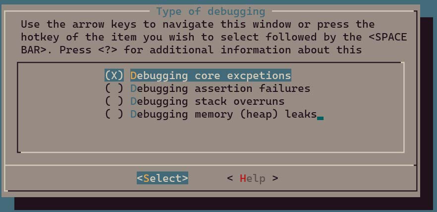
Refer to the following sections for selecting different options.
| Option | Chapter |
|---|---|
| Debugging core exception | Core Exception |
| Debugging assertion failure | Assertion Failure |
| Debugging stack overflow | Stack Overflow |
| Debugging memory (heap) leak | Memory Leak |
Exit menu and save configuration.
Build Demo Program
- Build executable binary: $ make
Note
- Build errors may asise depending on the type of problem selected. If this occurs, review the error message provided and adjust the configuration to enable additional features as recommended.
Run Demo Program
-
Download and run the application:
- Download and burn
wits.mcuboot.binto the TLSR9118 evaluation board (EVK) as described in the SDK Getting Started Guide. - Observe the behavior of the demonstration, show how the selected debugging problem manifests itself and how it can be diagnosed using the techniques described in this guide.
- Download and burn
Core Exception
Overview
The Core exceptions in the TLSR9118 can be caused by a variety of problems and can be recognized by the mcause register. This register helps diagnose the exact cause of the exception by providing a specific exception code.
Exception Code and Description
The following is a summary of common exception codes and their meanings in the mcause register:
| mcause[11:0] | Description |
|---|---|
| 0 | Command address not aligned |
| 1 | Command access error |
| 2 | Illegal command |
| 3 | Interrupt point |
| 4 | Load address not aligned |
| 5 | Load access error |
| 6 | Memory/AMO address not aligned |
| 7 | Memory/AMO access error |
| 8 | Environment call from user mode |
The TLSR9118 SDK includes a specialized demo application designed to demonstrate how to handle Illegal Command, Command Access Error and Interrupt Point exceptions. Implemented via a CLI command called jump_to_func, it simulates a jump to a specific command address to trigger these exceptions.
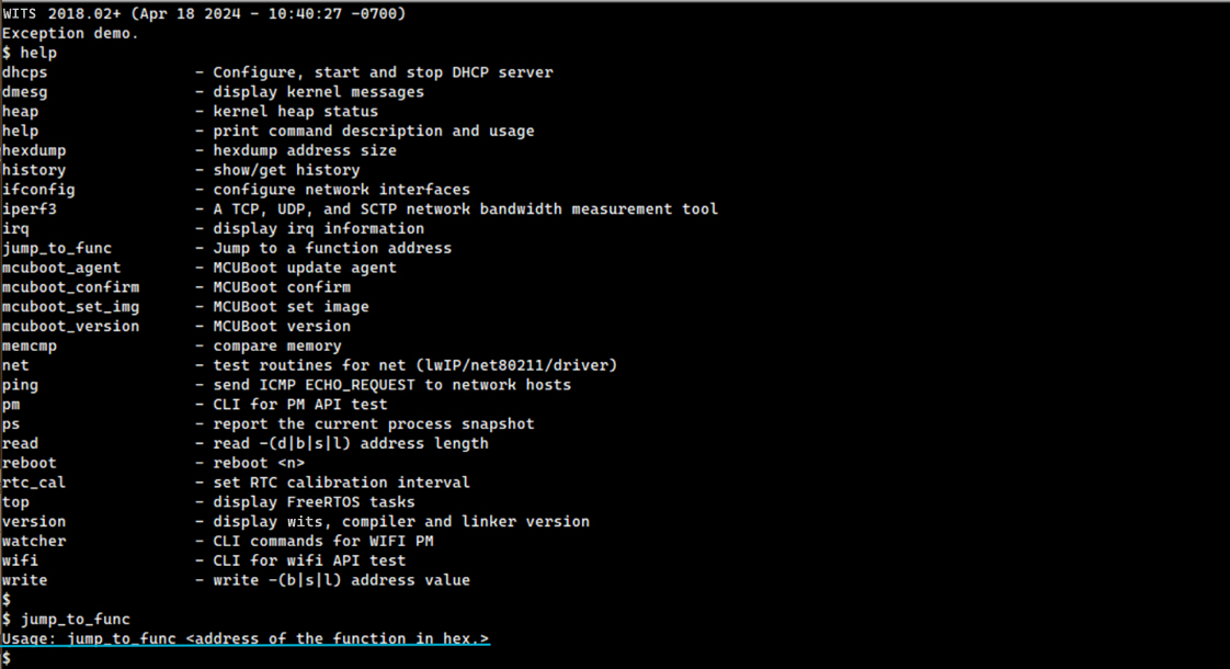
jump_to_func Operating Principle
jump_to_func is a simple CLI command that allows the user to jump to any command address, thus simulating a core exception. This command is particularly useful for educational and debugging purposes, as it can raise error conditions directly.
Trigger Different Exceptions
Specific exceptions can be triggered using jump_to_func by delivering different invalid address.
Illegal Command Exception
Delivering 0xc0000000 to the jump_to_func command results in an "Illegal Command" exception.
$ jump_to_func
Usage: jump_to_func <address of the function in hex.>
$
$ jump_to_func 0xc0000000
WITS 2018.02+ riscv32-elf-gcc.gnu (2022-02-07_nds32le-elf-mculib-v5-86807094a2f) 10.3.0
[003086.625667] BOARD: tlsr_w91 QFN40 EVB V1.0
[003086.625827] VFS: filesystem devfs mounted onto /dev
[003086.627695] PINCTRL: pin controller tlsr_w91,pinctrl registered
[003086.627906] GPIO: tlsr_w91,pinctrl registered as /dev/gpio
[003086.628180] atcwdt: @0xf1300000, clk=32768
[003086.628394] WDT: atcwdt registered as /dev/watchdog
[003086.628747] PINCTRL: atcspi200-xip/cs request pin 11
[003086.628947] PINCTRL: atcspi200-xip/clk request pin 12
[003086.629118] PINCTRL: atcspi200-xip/mosi request pin 13
[003086.629297] PINCTRL: atcspi200-xip/miso request pin 14
[003086.629488] PINCTRL: atcspi200-xip/hold request pin 9
[003086.629675] PINCTRL: atcspi200-xip/wp request pin 10
[003086.630177] EFUSE: efuse-tlsr_w91 registered as /dev/efuse
[003086.630314] trng version : 5e5e0010
[003086.630484] TRNG: trng registered as /dev/trng
[003086.630612] pke version : 0x5e5e0010
[003086.672324] Use fixed MAC address: 64.f9.47.f0.01.20
[003086.673338] 264 usec elapsed in downloading MAC FW.
[003087.967932] Wlan PM ctx init done
[003087.969345] UART: atcuart.0 registered as /dev/ttyS0
[003087.969499] CONSOLE: add /dev/ttyS0
[003087.969953] UART: atcuart.1 registered as /dev/ttyS1
[003087.970085] SOC: tlsr_w91
[003087.970611] Use fixed BLE public address: 01.02.03.04.05.06
[003087.972878] ble phy init 35
[003087.973030] PM feature : 0x1d
[003087.973811] PM LS : 6500+1120=7620
[003087.973979] PM SL : 6500+7100=13600
[003087.974147] PM DS : 11500+12800=24300
[003087.974326] PM HB : 1655000+60000=1715000
[003087.974589] PINCTRL: atcuart.0/txd request pin 22
[003087.974759] PINCTRL: atcuart.0/rxd request pin 21
[002333.517925] Unhandled Trap : Ilegal instruction (mcause = 0x2), mepc = 0xc0000000
[002333.525639] EPC:c0000000
[002333.528363] MSTATUS:00001880
[002333.531442] MXSTATUS:00000080
[002333.534611] MTVAL:00003003
[002333.537515] A0:c0000000 A1:00000000 A2:00000010 A3:00000001 A4:00000002 A5:ffffffff A6:00000008 A7:00210f37
[002333.547596] T0:8008e6f8 T1:001096f0 T2:00000000 T3:00210f2c T4:000001b0 T5:8008e71c T6:00000008
[002333.556635] S0:00000002 S1:0020d488 S2:ffffffff S3:00000001 S4:8010a220 S5:a5a5a5a5 S6:a5a5a5a5 S7:a5a5a5a5
[002333.566817] S8:a5a5a5a5 S9:a5a5a5a5 S10:a5a5a5a5 S11:a5a5a5a5
[002333.572828] FP:00000002 RA:8008e6fe
[002333.576440] sp:    0021cb6c
[002333.579428] IRQ stack:
[002333.581894]    base: 0021b590
[002333.584884]    size: 00000800
[002333.587880] ERROR: Stack pointer is not within the interrupt stack
[002333.594217] 0021b580: 00000000 00000000 00000000 00000000 00000000 00000000 00000000 00000000
[002333.602990] 0021b5a0: 00000000 00000000 00000000 00000000 00000000 00000000 00000000 00000000
[002333.611760] 0021b5c0: 00000000 00000000 00000000 00000000 00000000 00000000 00000000 00000000
[002333.620529] 0021b5e0: 00000000 00000000 00000000 00000000 00000000 00000000 00000000 00000000
[002333.629299] 0021b600: 00000000 00000000 00000000 00000000 00000000 00000000 00000000 00000000
[002333.638068] 0021b620: 00000000 00000000 00000000 00000000 00000000 00000000 00000000 00000000
[002333.646838] 0021b640: 00000000 00000000 00000000 00000000 00000000 00000000 00000000 00000000
[002333.655607] 0021b660: 00000000 00000000 00000000 00000000 00000000 00000000 00000000 00000000
[002333.664376] 0021b680: 00000000 00000000 00000000 00000000 00000000 00000000 00000000 00000000
[002333.673146] 0021b6a0: 00000000 00000000 00000000 00000000 00000000 00000000 00000000 00000000
[002333.681915] 0021b6c0: 00000000 00000000 00000000 00000000 00000000 00000000 00000000 00000000
[002333.690685] 0021b6e0: 00000000 00000000 00000000 00000000 00000000 00000000 00000000 00000000
[002333.699454] 0021b700: 00000000 00000000 00000000 00000000 00000000 00000000 00000000 00000000
[002333.708223] 0021b720: 00000000 00000000 00000000 00000000 00000000 00000000 00000000 00000000
[002333.716993] 0021b740: 00000000 00000000 00000000 00000000 00000000 00000000 00000000 00000000
[002333.725762] 0021b760: 00000000 00000000 00000000 00000000 00000000 00000000 00000000 00000000
[002333.734531] 0021b780: 00000000 00000000 00000000 00000000 00000000 00000000 00000000 00000000
[002333.743300] 0021b7a0: 00000000 00000000 00000000 00000000 00000000 00000000 00000000 00000000
[002333.752070] 0021b7c0: 00000000 00000000 00000000 00000000 00000000 00000000 00000000 00000000
[002333.760839] 0021b7e0: 00000000 00000000 00000000 00000000 00000000 00000000 00000000 00000000
[002333.769608] 0021b800: 00000000 00000000 00000000 00000000 00000000 00000000 00000000 00000000
[002333.778378] 0021b820: 00000000 00000000 00000000 00000000 00000000 00000000 00000000 00000000
[002333.787147] 0021b840: 00000000 00000000 00000000 00000000 00000000 00000000 00000000 00000000
[002333.795917] 0021b860: 00000000 00000000 00000000 00000000 00000000 00000000 00000000 00000000
[002333.804686] 0021b880: 00000000 00000000 00000000 00000000 00000000 00000000 00000000 00000000
[002333.813455] 0021b8a0: 00000000 00000000 00000000 00000000 00000000 00000000 00000000 00000000
[002333.822225] 0021b8c0: 00000000 00000000 00000000 00000000 00000000 00000000 00000000 00000000
[002333.830994] 0021b8e0: 00000000 00000000 00000000 00000000 00000000 00000000 00000000 00000000
[002333.839763] 0021b900: 00000000 00000000 00000000 00000000 00000000 00000000 00000000 00000000
[002333.848533] 0021b920: 00000000 00000000 00000000 00000000 00000000 00000000 00000000 00000000
[002333.857302] 0021b940: 00000000 00000000 00000000 00000000 00000000 00000000 00000000 00000000
[002333.866071] 0021b960: 00000000 00000000 00000000 00000000 00000000 00000000 00000000 00000000
[002333.874841] 0021b980: 00000000 00000000 00000000 00000000 00000000 00000000 00000000 00000000
[002333.883610] 0021b9a0: 00000000 00000000 00000000 00000000 00000000 00000000 00000000 00000000
[002333.892379] 0021b9c0: 00000000 00000000 00000000 00000000 00000000 00000000 00000000 00000000
[002333.901149] 0021b9e0: 00000000 00000000 00000000 00000000 00000000 00000000 00000000 00000000
[002333.909918] 0021ba00: 00000000 00000000 00000000 00000000 00000000 00000000 00000000 00000000
[002333.918687] 0021ba20: 00000000 00000000 00000000 00000000 00000000 00000000 00000000 00000000
[002333.927457] 0021ba40: 00000000 00000000 00000000 00000000 00000000 00000000 00000000 00000000
[002333.936226] 0021ba60: 00000000 00000000 00000000 00000000 00000000 00000000 00000000 00000000
[002333.944996] 0021ba80: 00000000 00000000 00000000 00000000 00000000 00000000 00000000 00000000
[002333.953765] 0021baa0: 00000000 00000000 00000000 00000000 00000000 00000000 00000000 00000000
[002333.962534] 0021bac0: 00000000 00000000 00000000 00000000 00000000 00000000 00000000 00000000
[002333.971304] 0021bae0: 00000000 00000000 00000000 00000000 00000000 00000000 00000000 00000000
[002333.980073] 0021bb00: 00000000 00000000 00000000 00000000 00000000 00000000 00000000 00000000
[002333.988842] 0021bb20: 00000000 00000000 00000000 00000000 00000000 00000000 00000000 00000000
[002333.997612] 0021bb40: 00000000 00000000 00000000 00000000 00000000 00000000 00000000 00000000
[002334.006381] 0021bb60: 00000000 00000000 00000000 00000000 00000000 00000000 00000000 00000000
[002334.015140] 0021bb80: 00000000 00000000 00000000 00000000 00000000 00000000 00000000 00000000
[002334.023904] 0021bba0: 00000000 00000000 00000000 00000000 00000000 00000000 00000000 00000000
[002334.032668] 0021bbc0: 00000000 00000000 00000000 00000000 00000000 00000000 00000000 00000000
[002334.041432] 0021bbe0: 00000000 00000000 00000000 00000000 00000000 00000000 00000000 00000000
[002334.050196] 0021bc00: 00000000 00000000 00000000 00000000 00000000 00000000 00000000 00000000
[002334.058961] 0021bc20: 00000000 00000000 00000000 00000000 00000000 00000000 00000000 00000000
[002334.067725] 0021bc40: 00000000 00000000 00000000 00000000 00000000 00000000 00000000 00000000
[002334.076489] 0021bc60: 00000000 00000000 00000000 00000000 0020c310 00203bf4 0020c9b8 80100c3a
[002334.085369] 0021bc80: 0020c310 00203bf4 0020c9b8 00000000 a5a5a5a5 a5a5a5a5 a5a5a5a5 0021bd2c
[002334.094348] 0021bca0: 00000005 00000000 00000100 8010b5ec 0010d29c 0020f780 0020fb80 8008e8e8
[002334.103275] 0021bcc0: a5a5a5a5 a5a5a5a5 0020fb80 00000084 a5a5a5a5 a5a5a5a5 8000b660 00202bc8
[002334.112286] 0021bce0: 80080020 0020d5f8 0020d5f8 8008eaa6 a5a5a5a5 0020fb80 0020f780 00000380
[002334.121282] 0021bd00: 80080020 0020d5f8 0020d5f8 0021cdc8 00000000 ffffffff 00222bb0 0010a9c6
[002334.130256] 0021bd20: 80122218 0000002d 6e9c9552 00215798 00000004 0020dea8 00223090 80100878
[002334.139219] 0021bd40: 00361682 00203bf4 0010d8d4 00206ef4 00000009 00000000 0010b70e 0000001c
[002334.148125] 0021bd60: 8b145395 00000004 002224e0 000002a0 00360aca 00000009 00206ef4 0010d8d4
[002334.157047] 0021bd80: 00203bf4 00361682 00000000 00000414 00000000 80001010 00000000 00000000
[002334.165916] sp:    0021cbfc
[002334.168909] User stack:
[002334.171460]   base: 0021bda0
[002334.174453]   size: 00000ff0
[002334.177447] 0021cbe0: 002065d4 c0000000 00000002 ffffffff 0020d488 00000002 8008e6fe c0000000
[002334.186418] 0021cc00: 00000080 00003003 00206658 8008e6fe 8008e6f8 001096f0 00000000 00000002
[002334.195335] 0021cc20: 0020d488 c0000000 00000000 00000010 00000001 00000002 ffffffff 00000008
[002334.204209] 0021cc40: 00210f37 ffffffff 00000001 8010a220 a5a5a5a5 a5a5a5a5 a5a5a5a5 a5a5a5a5
[002334.213225] 0021cc60: a5a5a5a5 a5a5a5a5 a5a5a5a5 00210f2c 000001b0 8008e71c 00000008 00001880
[002334.222194] 0021cc80: a5a5a5a5 a5a5a5a5 8010a220 c0000000 ffffffff 0020d488 00000002 8008e742
[002334.231211] 0021cca0: ffffffff 0020d488 00000002 800981cc 7095067b 00210d70 0020d3f8 00210f37
[002334.240195] 0021ccc0: 00210f20 00210f2d 00000000 00000000 00000000 00000000 00000000 00000000
[002334.249017] 0021cce0: 00000000 00000000 00000000 00000000 00000000 00000000 00000000 00000000
[002334.257787] 0021cd00: 00000000 00000000 00000000 00000000 00000000 00000000 00000000 00000000
[002334.266556] 0021cd20: 00000000 00000000 00000000 00000000 00000000 00000000 00000000 00000000
[002334.275325] 0021cd40: a5a5a5a5 a5a5a5a5 a5a5a5a5 a5a5a5a5 a5a5a5a5 80113eac 00210f20 800985b2
[002334.284378] 0021cd60: a5a5a5a5 0020d5fc 00202c04 800985c6 a5a5a5a5 0020d5fc 00202c04 800ff356
[002334.293400] 0021cd80: a5a5a5a5 a5a5a5a5 a5a5a5a5 00000000 a5a5a5a5 a5a5a5a5 a5a5a5a5 a5a5a5a5
[002334.306791] PID  PR  STWM  S  TASK
[002334.314053]   1   3  532   X  init                         (0x21bda0-0x21cd90, 0x21c6f8)
[002334.323036]   2   0  958   R  idle                         (0x20fc04-0x210c00, 0x210b1c)
[002334.332012]   4   3  683   B  knetd                        (0x21d0b0-0x21dca0, 0x21db5c)
[002334.340989]   3   5  199   B  ksofttimerd                  (0x20f780-0x20fb70, 0x20fa9c)
[002334.349966]   6   3  315   B  knet80211d/wlan0             (0x220d30-0x221320, 0x22121c)
[002334.358942]   7   3  303   B  rt_msg                       (0x221600-0x221bf0, 0x221acc)
[002334.367915]   8   7  48    B  ll                           (0x2227b0-0x222a20, 0x22291c)
[002334.376883]   5   3  571   B  tlsr_wlan-wlan fast taskq    (0x21f710-0x220100, 0x21fffc)
It can be known from the core dump:
-
'Illegal Command Exception' occurred due to accessing invalid address 0xc0000000 and
-
The 'init' task is running when this exception occurred.
Analyzing the dumped user stack reveals further call flow information to help locate the specific cause of this exception.
Note that the stack grows from the bottom to the top, i.e., from the high address to the low address, which means that the address of the command located at the bottom corresponds to the beginning of the call flow.
[002334.165916] sp:    0021cbfc
[002334.168909] User stack:
[002334.171460]   base: 0021bda0
[002334.174453]   size: 00000ff0
[002334.177447] 0021cbe0: 002065d4 c0000000 00000002 ffffffff 0020d488 00000002 8008e6fe c0000000
[002334.186418] 0021cc00: 00000080 00003003 00206658 8008e6fe 8008e6f8 001096f0 00000000 00000002
[002334.195335] 0021cc20: 0020d488 c0000000 00000000 00000010 00000001 00000002 ffffffff 00000008
[002334.204209] 0021cc40: 00210f37 ffffffff 00000001 8010a220 a5a5a5a5 a5a5a5a5 a5a5a5a5 a5a5a5a5
[002334.213225] 0021cc60: a5a5a5a5 a5a5a5a5 a5a5a5a5 00210f2c 000001b0 8008e71c 00000008 00001880
[002334.222194] 0021cc80: a5a5a5a5 a5a5a5a5 8010a220 c0000000 ffffffff 0020d488 00000002 8008e742
[002334.231211] 0021cca0: ffffffff 0020d488 00000002 800981cc 7095067b 00210d70 0020d3f8 00210f37
[002334.240195] 0021ccc0: 00210f20 00210f2d 00000000 00000000 00000000 00000000 00000000 00000000
[002334.249017] 0021cce0: 00000000 00000000 00000000 00000000 00000000 00000000 00000000 00000000
[002334.257787] 0021cd00: 00000000 00000000 00000000 00000000 00000000 00000000 00000000 00000000
[002334.266556] 0021cd20: 00000000 00000000 00000000 00000000 00000000 00000000 00000000 00000000
[002334.275325] 0021cd40: a5a5a5a5 a5a5a5a5 a5a5a5a5 a5a5a5a5 a5a5a5a5 80113eac 00210f20 800985b2
[002334.284378] 0021cd60: a5a5a5a5 0020d5fc 00202c04 800985c6 a5a5a5a5 0020d5fc 00202c04 800ff356
[002334.293400] 0021cd80: a5a5a5a5 a5a5a5a5 a5a5a5a5 00000000 a5a5a5a5 a5a5a5a5 a5a5a5a5 a5a5a5a5
[002334.306791] PID  PR  STWM  S  TASK
[002334.314053]   1   3  532   X  init                            (0x21bda0-0x21cd90, 0x21c6f8)
[002334.323036]   2   0  958   R  idle                            (0x20fc04-0x210c00, 0x210b1c)
[002334.332012]   4   3  683   B  knetd                           (0x21d0b0-0x21dca0, 0x21db5c)
[002334.340989]   3   5  199   B  ksofttimerd                     (0x20f780-0x20fb70, 0x20fa9c)
[002334.349966]   6   3  315   B  knet80211d/wlan0                (0x220d30-0x221320, 0x22121c)
[002334.358942]   7   3  303   B  rt_msg                          (0x221600-0x221bf0, 0x221acc)
[002334.367915]   8   7  48    B  ll                              (0x2227b0-0x222a20, 0x22291c)
[002334.376883]   5   3  571   B  tlsr_wlan-wlan fast taskq       (0x21f710-0x220100, 0x21fffc)
Candidate command addresses have been highlighted above according to the table in section Disassembler Use. In this particular case, there will be no ILM or ROM addresses involved, since the entire call flow takes place in the XIP flash area.
By searching these addresses in wits.dis, the call flow before the exception occurs can be revealed as follows:
(800ff356)
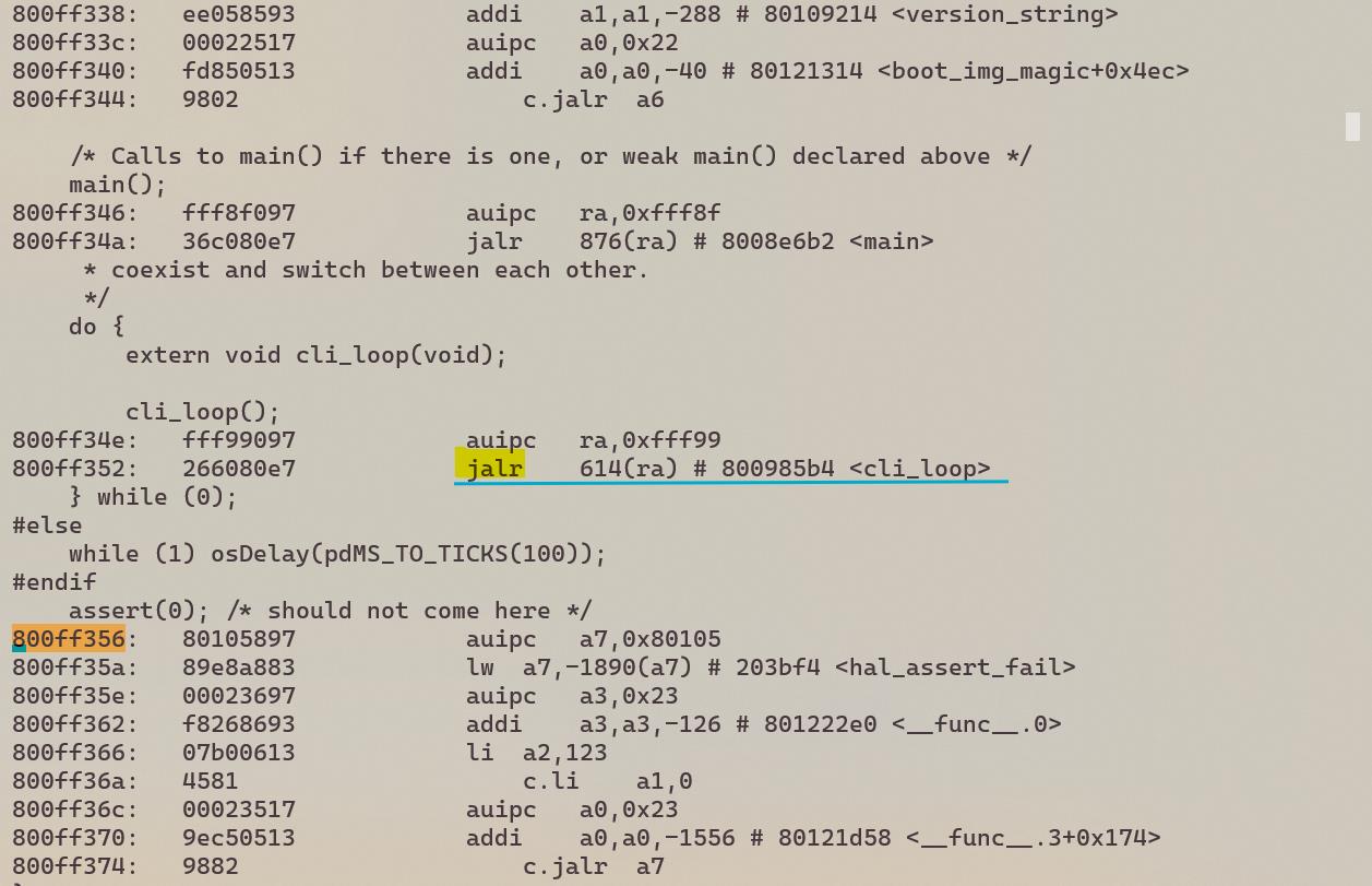
(800985c6)
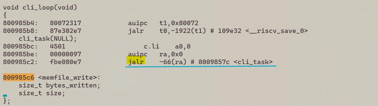
(800985b2)
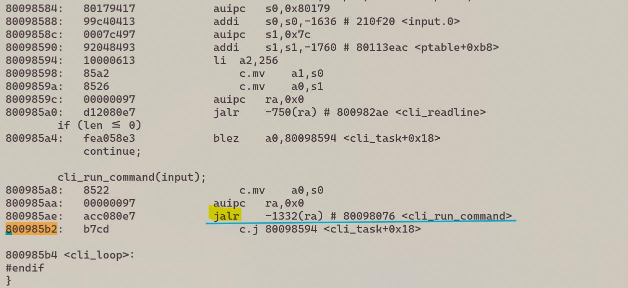
(800981cc)
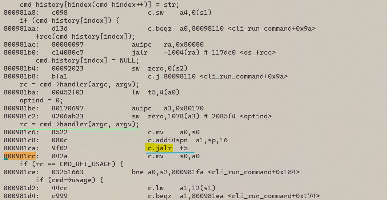
(8008e742)
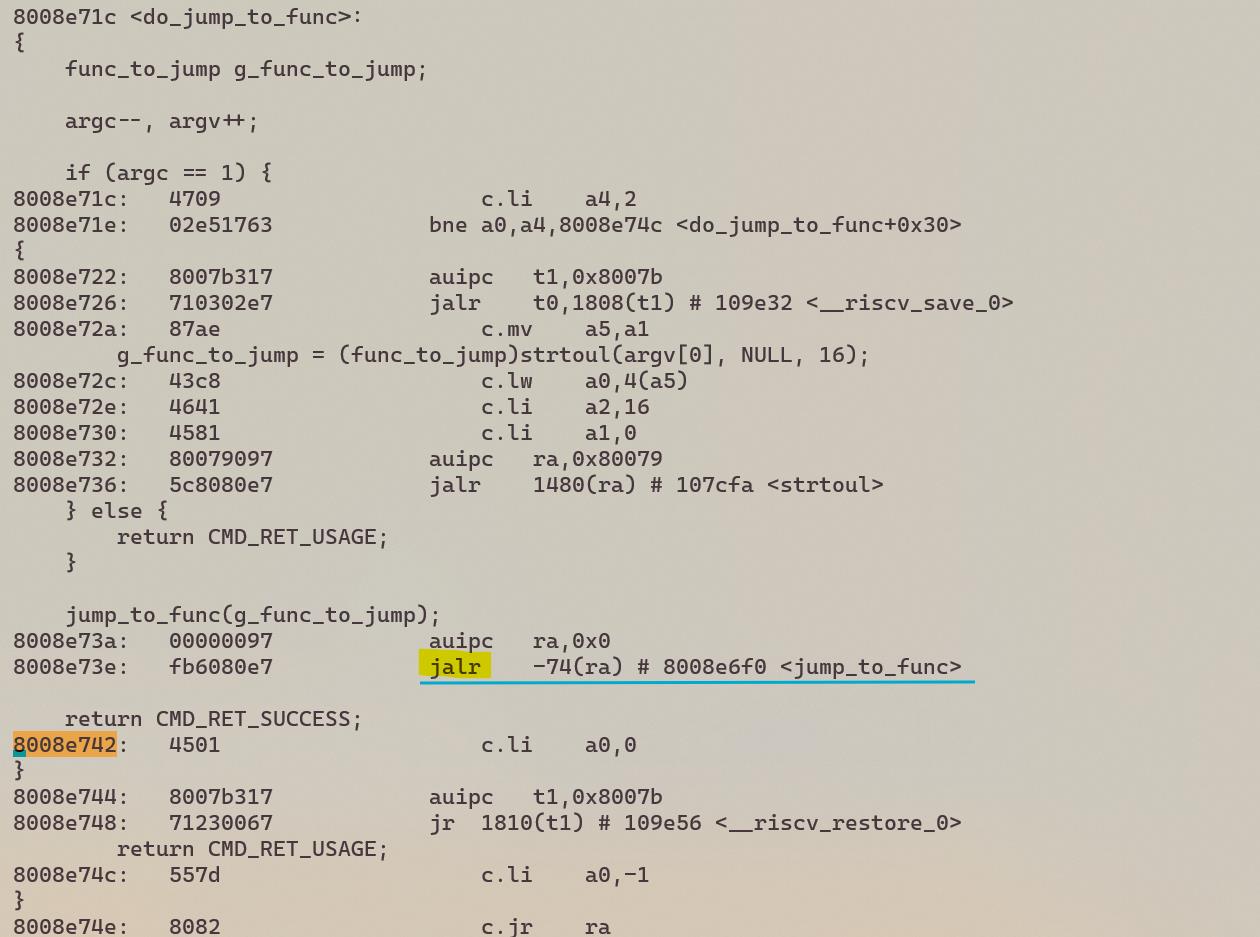
Therefore, the reconstructed call flow is:
cli_loop -> cli_task -> cli_run_command -> cmd->handler -> jump_to_func
As can be seen from this example, the command address emerging from a stack dump always corresponds to the command following a 'jalr' (i.e., jump and link) or similar commands.
This is because 'jalr' stores the return address (i.e., the address of the next command) in the 'ra' register, which is saved onto the stack in the prologue of the target function.
(wits.dis)
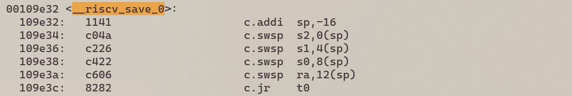
(wits_rom.dis)
Command Access Error
Delivering 0x12345678 to the jump_to_func command results in a "Command Access Error" exception.
WITS 2018.02+ (Apr 18 2024 - 10:40:27 -0700)
Exception demo.
$
$ jump_to_func
Usage: jump_to_func <address of the function in hex.>
$ jump_to_func 0x12345678
WITS 2018.02+ riscv32-elf-gcc.gnu (2022-02-07_nds32le-elf-mculib-v5-86807094a2f) 10.3.0
[000005.734989] BOARD: tlsr_w91 QFN40 EVB V1.0
[000005.735131] VFS: filesystem devfs mounted onto /dev
[000005.736982] PINCTRL: pin controller tlsr_w91,pinctrl registered
[000005.737176] GPIO: tlsr_w91,pinctrl registered as /dev/gpio
[000005.737429] atcwdt: @0xf1300000, clk=32768
[000005.737626] WDT: atcwdt registered as /dev/watchdog
[000005.737956] PINCTRL: atcspi200-xip/cs request pin 11
[000005.738139] PINCTRL: atcspi200-xip/clk request pin 12
[000005.738298] PINCTRL: atcspi200-xip/mosi request pin 13
[000005.738459] PINCTRL: atcspi200-xip/miso request pin 14
[000005.738634] PINCTRL: atcspi200-xip/hold request pin 9
[000005.738800] PINCTRL: atcspi200-xip/wp request pin 10
[000005.739284] EFUSE: efuse-tlsr_w91 registered as /dev/efuse
[000005.739406] trng version : 5e5e0010
[000005.739558] TRNG: trng registered as /dev/trng
[000005.739665] pke version : 0x5e5e0010
[000005.781668] Use fixed MAC address: 64.f9.47.f0.01.20
[000005.782652] 260 usec elapsed in downloading MAC FW.
[000007.077060] Wlan PM ctx init done
[000007.078476] UART: atcuart.0 registered as /dev/ttyS0
[000007.078614] CONSOLE: add /dev/ttyS0
[000007.079001] UART: atcuart.1 registered as /dev/ttyS1
[000007.079112] SOC: tlsr_w91
[000007.079607] Use fixed BLE public address: 01.02.03.04.05.06
[000007.081854] ble phy init 35
[000007.081975] PM feature : 0x1d
[000007.082731] PM LS : 6500+1120=7620
[000007.082885] PM SL : 6500+7100=13600
[000007.083031] PM DS : 11500+12800=24300
[000007.083189] PM HB : 1655000+60000=1715000
[000007.083429] PINCTRL: atcuart.0/txd request pin 22
[000007.083576] PINCTRL: atcuart.0/rxd request pin 21 [000020.695688] Unhandled Trap : Instruction access fault (mcause = 0x1), mepc = 0x12345678
[000020.703912] EPC:12345678
[000020.706636] MSTATUS:00001880
[000020.709714] MXSTATUS:00000080
[000020.712884] MTVAL:12345678
[000020.715788] A0:12345678 A1:00000000 A2:00000010 A3:00000001 A4:00000002 A5:ffffffff A6:00000004 A7:00210f37
[000020.725855] T0:8008e6f8 T1:001096f0 T2:00000000 T3:00210f2c T4:000001b0 T5:8008e71c T6:00000008
[000020.734882] S0:00000002 S1:0020d488 S2:ffffffff S3:00000001 S4:8010a220 S5:a5a5a5a5 S6:a5a5a5a5 S7:a5a5a5a5
[000020.745053] S8:a5a5a5a5 S9:a5a5a5a5 S10:a5a5a5a5 S11:a5a5a5a5
[000020.751052] FP:00000002 RA:8008e6fe
[000020.754664] sp:     0021cb6c
[000020.757652] IRQ stack:
[000020.760118]   base: 0021b590
[000020.763108]   size: 00000800
[000020.766104] ERROR: Stack pointer is not within the interrupt stack
[000020.772441] 0021b580: 00000000 00000000 00000000 00000000 00000000 00000000 00000000 00000000
[000020.781203] 0021b5a0: 00000000 00000000 00000000 00000000 00000000 00000000 00000000 00000000
[000020.789961] 0021b5c0: 00000000 00000000 00000000 00000000 00000000 00000000 00000000 00000000
[000020.798718] 0021b5e0: 00000000 00000000 00000000 00000000 00000000 00000000 00000000 00000000
[000020.807476] 0021b600: 00000000 00000000 00000000 00000000 00000000 00000000 00000000 00000000
[000020.816234] 0021b620: 00000000 00000000 00000000 00000000 00000000 00000000 00000000 00000000
[000020.824991] 0021b640: 00000000 00000000 00000000 00000000 00000000 00000000 00000000 00000000
[000020.833749] 0021b660: 00000000 00000000 00000000 00000000 00000000 00000000 00000000 00000000
[000020.842507] 0021b680: 00000000 00000000 00000000 00000000 00000000 00000000 00000000 00000000
[000020.851265] 0021b6a0: 00000000 00000000 00000000 00000000 00000000 00000000 00000000 00000000
[000020.860022] 0021b6c0: 00000000 00000000 00000000 00000000 00000000 00000000 00000000 00000000
[000020.868780] 0021b6e0: 00000000 00000000 00000000 00000000 00000000 00000000 00000000 00000000
[000020.877538] 0021b700: 00000000 00000000 00000000 00000000 00000000 00000000 00000000 00000000
[000020.886296] 0021b720: 00000000 00000000 00000000 00000000 00000000 00000000 00000000 00000000
[000020.895053] 0021b740: 00000000 00000000 00000000 00000000 00000000 00000000 00000000 00000000
[000020.903811] 0021b760: 00000000 00000000 00000000 00000000 00000000 00000000 00000000 00000000
[000020.912569] 0021b780: 00000000 00000000 00000000 00000000 00000000 00000000 00000000 00000000
[000020.921326] 0021b7a0: 00000000 00000000 00000000 00000000 00000000 00000000 00000000 00000000
[000020.930084] 0021b7c0: 00000000 00000000 00000000 00000000 00000000 00000000 00000000 00000000
[000020.938842] 0021b7e0: 00000000 00000000 00000000 00000000 00000000 00000000 00000000 00000000
[000020.947599] 0021b800: 00000000 00000000 00000000 00000000 00000000 00000000 00000000 00000000
[000020.956357] 0021b820: 00000000 00000000 00000000 00000000 00000000 00000000 00000000 00000000
[000020.965115] 0021b840: 00000000 00000000 00000000 00000000 00000000 00000000 00000000 00000000
[000020.973872] 0021b860: 00000000 00000000 00000000 00000000 00000000 00000000 00000000 00000000
[000020.982630] 0021b880: 00000000 00000000 00000000 00000000 00000000 00000000 00000000 00000000
[000020.991388] 0021b8a0: 00000000 00000000 00000000 00000000 00000000 00000000 00000000 00000000
[000021.000145] 0021b8c0: 00000000 00000000 00000000 00000000 00000000 00000000 00000000 00000000
[000021.008887] 0021b8e0: 00000000 00000000 00000000 00000000 00000000 00000000 00000000 00000000
[000021.017635] 0021b900: 00000000 00000000 00000000 00000000 00000000 00000000 00000000 00000000
[000021.026387] 0021b920: 00000000 00000000 00000000 00000000 00000000 00000000 00000000 00000000
[000021.035140] 0021b940: 00000000 00000000 00000000 00000000 00000000 00000000 00000000 00000000
[000021.043892] 0021b960: 00000000 00000000 00000000 00000000 00000000 00000000 00000000 00000000
[000021.052644] 0021b980: 00000000 00000000 00000000 00000000 00000000 00000000 00000000 00000000
[000021.061397] 0021b9a0: 00000000 00000000 00000000 00000000 00000000 00000000 00000000 00000000
[000021.070149] 0021b9c0: 00000000 00000000 00000000 00000000 00000000 00000000 00000000 00000000
[000021.078902] 0021b9e0: 00000000 00000000 00000000 00000000 00000000 00000000 00000000 00000000
[000021.087654] 0021ba00: 00000000 00000000 00000000 00000000 00000000 00000000 00000000 00000000
[000021.096407] 0021ba20: 00000000 00000000 00000000 00000000 00000000 00000000 00000000 00000000
[000021.105159] 0021ba40: 00000000 00000000 00000000 00000000 00000000 00000000 00000000 00000000
[000021.113917] 0021ba60: 00000000 00000000 00000000 00000000 00000000 00000000 00000000 00000000
[000021.122675] 0021ba80: 00000000 00000000 00000000 00000000 00000000 00000000 00000000 00000000
[000021.131432] 0021baa0: 00000000 00000000 00000000 00000000 00000000 00000000 00000000 00000000
[000021.140190] 0021bac0: 00000000 00000000 00000000 00000000 00000000 00000000 00000000 00000000
[000021.148948] 0021bae0: 00000000 00000000 00000000 00000000 00000000 00000000 00000000 00000000
[000021.157706] 0021bb00: 00000000 00000000 00000000 00000000 00000000 00000000 00000000 00000000
[000021.166463] 0021bb20: 00000000 00000000 00000000 00000000 00000000 00000000 00000000 00000000
[000021.175221] 0021bb40: 00000000 00000000 00000000 00000000 00000000 00000000 00000000 00000000
[000021.183979] 0021bb60: 00000000 00000000 00000000 00000000 00000000 00000000 00000000 00000000
[000021.192736] 0021bb80: 00000000 00000000 00000000 00000000 00000000 00000000 00000000 00000000
[000021.201494] 0021bba0: 00000000 00000000 00000000 00000000 00000000 00000000 00000000 00000000
[000021.210252] 0021bbc0: 00000000 00000000 00000000 00000000 00000000 00000000 00000000 00000000
[000021.219009] 0021bbe0: 00000000 00000000 00000000 00000000 00000000 00000000 00000000 00000000
[000021.227767] 0021bc00: 00000000 00000000 00000000 00000000 00000000 00000000 00000000 00000000
[000021.236525] 0021bc20: 00000000 00000000 00000000 00000000 00000000 00000000 00000000 00000000
[000021.245283] 0021bc40: 00000000 00000000 00000000 00000000 00000000 00000000 00000000 00000000
[000021.254040] 0021bc60: 00000000 00000000 00000000 00000000 0020c310 00203bf4 0020c9b8 80100c3a
[000021.262914] 0021bc80: 0020c310 00203bf4 0020c9b8 00000000 a5a5a5a5 a5a5a5a5 a5a5a5a5 0021bd2c
[000021.271887] 0021bca0: 00000005 00000000 00000100 8010b5ec 0010d29c 0020f780 0020fb80 8008e8e8
[000021.280807] 0021bcc0: a5a5a5a5 a5a5a5a5 0020fb80 00000084 a5a5a5a5 a5a5a5a5 8000b660 00202bc8
[000021.289807] 0021bce0: 80080020 0020d5f8 0020d5f8 8008eaa6 a5a5a5a5 0020fb80 0020f780 00000380
[000021.298791] 0021bd00: 80080020 0020d5f8 0020d5f8 0021cdc8 00000000 ffffffff 00222f60 0010a9c6
[000021.307753] 0021bd20: 80122218 00000000 0bf04f4c 00215798 00000004 0020dea8 002225d0 80100878
[000021.316694] 0021bd40: 00004590 00203bf4 0010d8d4 00206ef4 00000009 00000000 0010b70e 0000001c
[000021.325578] 0021bd60: 013975b9 00000000 00222490 000002a0 000039d8 00000009 00206ef4 0010d8d4
[000021.334472] 0021bd80: 00203bf4 00004590 00000000 00000414 00000000 80001010 00000000 00000000
[000021.343319] sp: 0021cbfc
[000021.346312] User stack:
[000021.348863] base: 0021bda0
[000021.351856] size: 00000ff0
[000021.354850] 0021cbe0: 002065d4 12345678 00000001 ffffffff 0020d488 00000002 8008e6fe 12345678
[000021.363809] 0021cc00: 00000080 12345678 00206658 8008e6fe 8008e6f8 001096f0 00000000 00000002
[000021.372735] 0021cc20: 0020d488 12345678 00000000 00000010 00000001 00000002 ffffffff 00000004
[000021.381597] 0021cc40: 00210f37 ffffffff 00000001 8010a220 a5a5a5a5 a5a5a5a5 a5a5a5a5 a5a5a5a5
[000021.390601] 0021cc60: a5a5a5a5 a5a5a5a5 a5a5a5a5 00210f2c 000001b0 8008e71c 00000008 00001880
[000021.399559] 0021cc80: a5a5a5a5 a5a5a5a5 8010a220 12345678 ffffffff 0020d488 00000002 8008e742
[000021.408563] 0021cca0: ffffffff 0020d488 00000002 800981cc 0e085bef 00210d70 0020d3f8 00210f37
[000021.417530] 0021ccc0: 00210f20 00210f2d 00000000 00000000 00000000 00000000 00000000 00000000
[000021.426341] 0021cce0: 00000000 00000000 00000000 00000000 00000000 00000000 00000000 00000000
[000021.435099] 0021cd00: 00000000 00000000 00000000 00000000 00000000 00000000 00000000 00000000
[000021.443856] 0021cd20: 00000000 00000000 00000000 00000000 00000000 00000000 00000000 00000000
[000021.452614] 0021cd40: a5a5a5a5 a5a5a5a5 a5a5a5a5 a5a5a5a5 a5a5a5a5 80113eac 00210f20 800985b2
[000021.461655] 0021cd60: a5a5a5a5 0020d5fc 00202c04 800985c6 a5a5a5a5 0020d5fc 00202c04 800ff356
[000021.470665] 0021cd80: a5a5a5a5 a5a5a5a5 a5a5a5a5 00000000 a5a5a5a5 a5a5a5a5 a5a5a5a5 a5a5a5a5
[000021.484043] PID  PR  STWM  S  TASK
[000021.491295]   1   3  532   X  init                           (0x21bda0-0x21cd90, 0x21c6f8)
[000021.500266]   2   0  966   R  idle                           (0x20fc04-0x210c00, 0x210b1c)
[000021.509233]   4   3  683   B  knetd                          (0x21d0b0-0x21dca0, 0x21db5c)
[000021.518199]   3   5  199   B  ksofttimerd                    (0x20f780-0x20fb70, 0x20fa9c)
[000021.527165]   7   3  303   B  rt_msg                         (0x221600-0x221bf0, 0x221acc)
[000021.536132]   6   3  315   B  knet80211d/wlan0               (0x220d30-0x221320, 0x22121c)
[000021.545098]   8   7  48    B  ll                             (0x222b60-0x222dd0, 0x222ccc)
[000021.554060]   5   3  571   B  tlsr_wlan-wlan fast taskq      (0x21f710-0x220100, 0x21fffc)
Breakpoint Exception
Delivering the address corresponding to the ebreak command (0x422 in this case) to the jump_to_func command results in a 'breakpoint' exception.
WITS 2018.02+ (Apr 18 2024 - 10:40:27 -0700)
Exception demo.
$
$
$ jump_to_func
Usage: jump_to_func <address of the function in hex.>
$
$ jump_to_func 0x422
WITS 2018.02+ riscv32-elf-gcc.gnu (2022-02-07_nds32le-elf-mculib-v5-86807094a2f) 10.3.0
[000005.734989] BOARD: tlsr_w91 QFN40 EVB V1.0
[000005.735131] VFS: filesystem devfs mounted onto /dev
[000005.736982] PINCTRL: pin controller tlsr_w91,pinctrl registered
[000005.737176] GPIO: tlsr_w91,pinctrl registered as /dev/gpio
[000005.737444] atcwdt: @0xf1300000, clk=32768
[000005.737641] WDT: atcwdt registered as /dev/watchdog
[000005.737971] PINCTRL: atcspi200-xip/cs request pin 11
[000005.738154] PINCTRL: atcspi200-xip/clk request pin 12
[000005.738313] PINCTRL: atcspi200-xip/mosi request pin 13
[000005.738474] PINCTRL: atcspi200-xip/miso request pin 14
[000005.738649] PINCTRL: atcspi200-xip/hold request pin 9
[000005.738815] PINCTRL: atcspi200-xip/wp request pin 10
[000005.739299] EFUSE: efuse-tlsr_w91 registered as /dev/efuse
[000005.739421] trng version : 5e5e0010
[000005.739573] TRNG: trng registered as /dev/trng
[000005.739680] pke version : 0x5e5e0010
[000005.781669] Use fixed MAC address: 64.f9.47.f0.01.20
[000005.782653] 260 usec elapsed in downloading MAC FW.
[000007.077076] Wlan PM ctx init done
[000007.078495] UART: atcuart.0 registered as /dev/ttyS0
[000007.078632] CONSOLE: add /dev/ttyS0
[000007.079019] UART: atcuart.1 registered as /dev/ttyS1
[000007.079130] SOC: tlsr_w91
[000007.079625] Use fixed BLE public address: 01.02.03.04.05.06
[000007.081873] ble phy init 35
[000007.081994] PM feature : 0x1d
[000007.082750] PM LS : 6500+1120=7620
[000007.082904] PM SL : 6500+7100=13600
[000007.083050] PM DS : 11500+12800=24300
[000007.083207] PM HB : 1655000+60000=1715000
[000007.083447] PINCTRL: atcuart.0/txd request pin 22
[000007.083594] PINCTRL: atcuart.0/rxd request pin 21
[000092.145991] Unhandled Trap : Breakpoint (ebreak) (mcause = 0x3), mepc = 0x422
[000092.153305] EPC:00000422
[000092.156030] MSTATUS:00001880
[000092.159108] MXSTATUS:00000080
[000092.162277] MTVAL:00000000
[000092.165182] A0:00000422 A1:00000000 A2:00000010 A3:00000001 A4:00000002 A5:ffffffff A6:00000004 A7:00210f32
[000092.175223] T0:8008e6f8 T1:001096f0 T2:00000000 T3:00210f2c T4:000001b0 T5:8008e71c T6:00000008
[000092.184250] S0:00000002 S1:0020d488 S2:ffffffff S3:00000001 S4:8010a220 S5:a5a5a5a5 S6:a5a5a5a5 S7:a5a5a5a5
[000092.194421] S8:a5a5a5a5 S9:a5a5a5a5 S10:a5a5a5a5 S11:a5a5a5a5
[000092.200420] FP:00000002 RA:8008e6fe
[000092.204032] sp:     0021cb6c
[000092.207020] IRQ stack:
[000092.209485]   base: 0021b590
[000092.212476]   size: 00000800
[000092.215472] ERROR: Stack pointer is not within the interrupt stack
[000092.221809] 0021b580: 00000000 00000000 00000000 00000000 00000000 00000000 00000000 00000000
[000092.230571] 0021b5a0: 00000000 00000000 00000000 00000000 00000000 00000000 00000000 00000000
[000092.239328] 0021b5c0: 00000000 00000000 00000000 00000000 00000000 00000000 00000000 00000000
[000092.248086] 0021b5e0: 00000000 00000000 00000000 00000000 00000000 00000000 00000000 00000000
[000092.256844] 0021b600: 00000000 00000000 00000000 00000000 00000000 00000000 00000000 00000000
[000092.265601] 0021b620: 00000000 00000000 00000000 00000000 00000000 00000000 00000000 00000000
[000092.274359] 0021b640: 00000000 00000000 00000000 00000000 00000000 00000000 00000000 00000000
[000092.283117] 0021b660: 00000000 00000000 00000000 00000000 00000000 00000000 00000000 00000000
[000092.291875] 0021b680: 00000000 00000000 00000000 00000000 00000000 00000000 00000000 00000000
[000092.300632] 0021b6a0: 00000000 00000000 00000000 00000000 00000000 00000000 00000000 00000000
[000092.309390] 0021b6c0: 00000000 00000000 00000000 00000000 00000000 00000000 00000000 00000000
[000092.318148] 0021b6e0: 00000000 00000000 00000000 00000000 00000000 00000000 00000000 00000000
[000092.326905] 0021b700: 00000000 00000000 00000000 00000000 00000000 00000000 00000000 00000000
[000092.335663] 0021b720: 00000000 00000000 00000000 00000000 00000000 00000000 00000000 00000000
[000092.344421] 0021b740: 00000000 00000000 00000000 00000000 00000000 00000000 00000000 00000000
[000092.353179] 0021b760: 00000000 00000000 00000000 00000000 00000000 00000000 00000000 00000000
[000092.361936] 0021b780: 00000000 00000000 00000000 00000000 00000000 00000000 00000000 00000000
[000092.370694] 0021b7a0: 00000000 00000000 00000000 00000000 00000000 00000000 00000000 00000000
[000092.379451] 0021b7c0: 00000000 00000000 00000000 00000000 00000000 00000000 00000000 00000000
[000092.388209] 0021b7e0: 00000000 00000000 00000000 00000000 00000000 00000000 00000000 00000000
[000092.396967] 0021b800: 00000000 00000000 00000000 00000000 00000000 00000000 00000000 00000000
[000092.405724] 0021b820: 00000000 00000000 00000000 00000000 00000000 00000000 00000000 00000000
[000092.414482] 0021b840: 00000000 00000000 00000000 00000000 00000000 00000000 00000000 00000000
[000092.423240] 0021b860: 00000000 00000000 00000000 00000000 00000000 00000000 00000000 00000000
[000092.431998] 0021b880: 00000000 00000000 00000000 00000000 00000000 00000000 00000000 00000000
[000092.440755] 0021b8a0: 00000000 00000000 00000000 00000000 00000000 00000000 00000000 00000000
[000092.449513] 0021b8c0: 00000000 00000000 00000000 00000000 00000000 00000000 00000000 00000000
[000092.458271] 0021b8e0: 00000000 00000000 00000000 00000000 00000000 00000000 00000000 00000000
[000092.467029] 0021b900: 00000000 00000000 00000000 00000000 00000000 00000000 00000000 00000000
[000092.475786] 0021b920: 00000000 00000000 00000000 00000000 00000000 00000000 00000000 00000000
[000092.484544] 0021b940: 00000000 00000000 00000000 00000000 00000000 00000000 00000000 00000000
[000092.493302] 0021b960: 00000000 00000000 00000000 00000000 00000000 00000000 00000000 00000000
[000092.502059] 0021b980: 00000000 00000000 00000000 00000000 00000000 00000000 00000000 00000000
[000092.510817] 0021b9a0: 00000000 00000000 00000000 00000000 00000000 00000000 00000000 00000000
[000092.519575] 0021b9c0: 00000000 00000000 00000000 00000000 00000000 00000000 00000000 00000000
[000092.528332] 0021b9e0: 00000000 00000000 00000000 00000000 00000000 00000000 00000000 00000000
[000092.537090] 0021ba00: 00000000 00000000 00000000 00000000 00000000 00000000 00000000 00000000
[000092.545847] 0021ba20: 00000000 00000000 00000000 00000000 00000000 00000000 00000000 00000000
[000092.554605] 0021ba40: 00000000 00000000 00000000 00000000 00000000 00000000 00000000 00000000
[000092.563363] 0021ba60: 00000000 00000000 00000000 00000000 00000000 00000000 00000000 00000000
[000092.572121] 0021ba80: 00000000 00000000 00000000 00000000 00000000 00000000 00000000 00000000
[000092.580878] 0021baa0: 00000000 00000000 00000000 00000000 00000000 00000000 00000000 00000000
[000092.589636] 0021bac0: 00000000 00000000 00000000 00000000 00000000 00000000 00000000 00000000
[000092.598394] 0021bae0: 00000000 00000000 00000000 00000000 00000000 00000000 00000000 00000000
[000092.607152] 0021bb00: 00000000 00000000 00000000 00000000 00000000 00000000 00000000 00000000
[000092.615909] 0021bb20: 00000000 00000000 00000000 00000000 00000000 00000000 00000000 00000000
[000092.624667] 0021bb40: 00000000 00000000 00000000 00000000 00000000 00000000 00000000 00000000
[000092.633425] 0021bb60: 00000000 00000000 00000000 00000000 00000000 00000000 00000000 00000000
[000092.642182] 0021bb80: 00000000 00000000 00000000 00000000 00000000 00000000 00000000 00000000
[000092.650940] 0021bba0: 00000000 00000000 00000000 00000000 00000000 00000000 00000000 00000000
[000092.659698] 0021bbc0: 00000000 00000000 00000000 00000000 00000000 00000000 00000000 00000000
[000092.668455] 0021bbe0: 00000000 00000000 00000000 00000000 00000000 00000000 00000000 00000000
[000092.677213] 0021bc00: 00000000 00000000 00000000 00000000 00000000 00000000 00000000 00000000
[000092.685971] 0021bc20: 00000000 00000000 00000000 00000000 00000000 00000000 00000000 00000000
[000092.694728] 0021bc40: 00000000 00000000 00000000 00000000 00000000 00000000 00000000 00000000
[000092.703486] 0021bc60: 00000000 00000000 00000000 00000000 0020c310 00203bf4 0020c9b8 80100c3a
[000092.712359] 0021bc80: 0020c310 00203bf4 0020c9b8 00000000 a5a5a5a5 a5a5a5a5 a5a5a5a5 0021bd2c
[000092.721332] 0021bca0: 00000005 00000000 00000100 8010b5ec 0010d29c 0020f780 0020fb80 8008e8e8
[000092.730253] 0021bcc0: a5a5a5a5 a5a5a5a5 0020fb80 00000084 a5a5a5a5 a5a5a5a5 8000b660 00202bc8
[000092.739252] 0021bce0: 80080020 0020d5f8 0020d5f8 8008eaa6 a5a5a5a5 0020fb80 0020f780 00000380
[000092.748236] 0021bd00: 80080020 0020d5f8 0020d5f8 0021cdc8 00000000 ffffffff 00222f60 0010a9c6
[000092.757198] 0021bd20: 80122218 00000000 36a53b6d 00215798 00000004 0020dea8 002225d0 80100878
[000092.766144] 0021bd40: 00015caa 00203bf4 0010d8d4 00206ef4 00000009 00000000 0010b70e 0000001c
[000092.775033] 0021bd60: 057bb479 00000000 00222490 000002a0 000150f2 00000009 00206ef4 0010d8d4
[000092.783932] 0021bd80: 00203bf4 00015caa 00000000 00000414 00000000 80001010 00000000 00000000
[000092.792785] sp:     0021cbfc
[000092.795778] User stack:
[000092.798328]   base: 0021bda0
[000092.801322]   size: 00000ff0
[000092.804316] 0021cbe0: 002065d4 00000422 00000003 ffffffff 0020d488 00000002 8008e6fe 00000422
[000092.813222] 0021cc00: 00000080 00000000 00206658 8008e6fe 8008e6f8 001096f0 00000000 00000002
[000092.822111] 0021cc20: 0020d488 00000422 00000000 00000010 00000001 00000002 ffffffff 00000004
[000092.830948] 0021cc40: 00210f32 ffffffff 00000001 8010a220 a5a5a5a5 a5a5a5a5 a5a5a5a5 a5a5a5a5
[000092.839952] 0021cc60: a5a5a5a5 a5a5a5a5 a5a5a5a5 00210f2c 000001b0 8008e71c 00000008 00001880
[000092.848909] 0021cc80: a5a5a5a5 a5a5a5a5 8010a220 00000422 ffffffff 0020d488 00000002 8008e742
[000092.857887] 0021cca0: ffffffff 0020d488 00000002 800981cc 389ecf69 00210d70 0020d3f8 00210f32
[000092.866860] 0021ccc0: 00210f20 00210f2d 00000000 00000000 00000000 00000000 00000000 00000000
[000092.875670] 0021cce0: 00000000 00000000 00000000 00000000 00000000 00000000 00000000 00000000
[000092.884428] 0021cd00: 00000000 00000000 00000000 00000000 00000000 00000000 00000000 00000000
[000092.893186] 0021cd20: 00000000 00000000 00000000 00000000 00000000 00000000 00000000 00000000
[000092.901944] 0021cd40: a5a5a5a5 a5a5a5a5 a5a5a5a5 a5a5a5a5 a5a5a5a5 80113eac 00210f20 800985b2
[000092.910985] 0021cd60: a5a5a5a5 0020d5fc 00202c04 800985c6 a5a5a5a5 0020d5fc 00202c04 800ff356
[000092.919994] 0021cd80: a5a5a5a5 a5a5a5a5 a5a5a5a5 00000000 a5a5a5a5 a5a5a5a5 a5a5a5a5 a5a5a5a5
[000092.933368] PID  PR  STWM  S  TASK
[000092.940620]   1   3  532   X  init                           (0x21bda0-0x21cd90, 0x21c6f8)
[000092.949592]   2   0  966   R  idle                           (0x20fc04-0x210c00, 0x210b1c)
[000092.958557]   4   3  683   B  knetd                          (0x21d0b0-0x21dca0, 0x21db5c)
[000092.967518]   3   5  199   B  ksofttimerd                    (0x20f780-0x20fb70, 0x20fa9c)
[000092.976479]   7   3  303   B  rt_msg                         (0x221600-0x221bf0, 0x221acc)
[000092.985440]   6   3  315   B  knet80211d/wlan0               (0x220d30-0x221320, 0x22121c)
[000092.994401]   8   7  48    B  ll                             (0x222b60-0x222dd0, 0x222ccc)
[000093.003357]   5   3  571   B  tlsr_wlan-wlan fast taskq      (0x21f710-0x220100, 0x21fffc)
Assertion Failure
Overview
The assertion failure is critical to identifying the exact location of a fault, which aids in debugging and troubleshooting in an operational environment.
Purpose of Assertion
The assertion provides a structured way to pinpoint and express specific failures. Serve as direct indicators of the failure of predefined conditions, they help in the early detection and repair of potential errors.
Implement Assertion
Assertion Usage
(1) Include the header file <assert.h> in code. (2) Specify the condition under which the expectation is true.
Examples of the use of assertions are provided below. This technique ensures that problems are recognized timely and avoids more complex problems caused by overlooking initial errors.
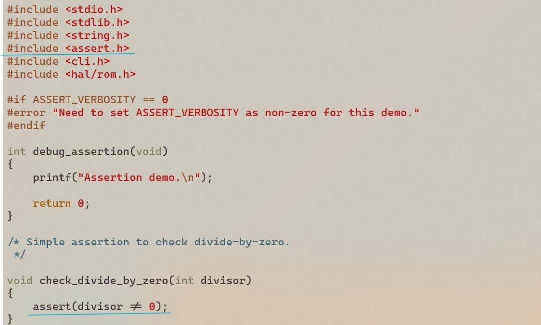
Configure Assertion Verbosity
The verbosity of the assertion message can be set to one of three levels, allowing the developer to choose the amount of detail provided during troubleshooting. This setting can be adjusted during the build configuration process, as shown below:
Navigate to:Kernel -> General Setup -> Default
By configuring the verbosity, developers can customize the assertion output to the needs of debugging or diagnostic tasks.
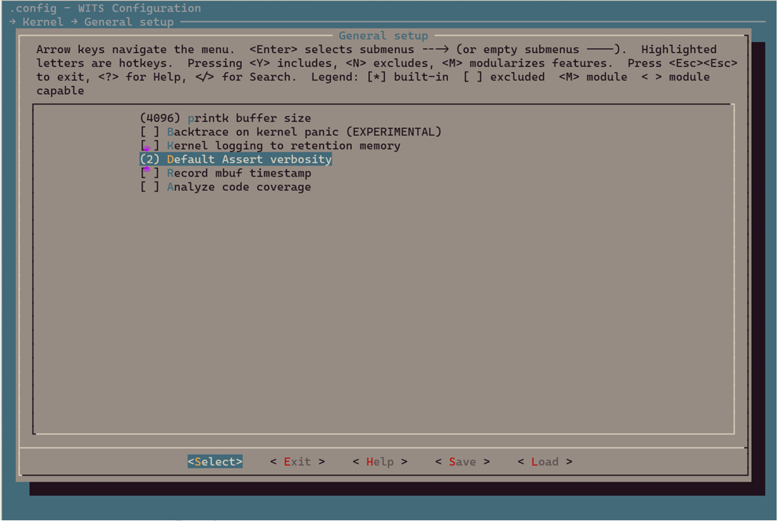
| Assertion Verbosity | Show Assertion Conditions | Show Function Name and Line Mumber | Impact on Memory Usage |
|---|---|---|---|
| 2 (default) | Y | Y | High (**) |
| 1 | Y | N | Low |
| 0 (*) | N | N | None |
- (*) Setting the verbosity to 0 completely disables all assertions, which is usually not recommended.
- (**) This is due to the possibility of including long function names in the executable binary.
Assertion Failure in Demo
By running the demo application, it shows how to use assertions in the application. See section Demonstrate how to debug with tlsr9118-sdk to build and run the debugging demo.
There will be a CLI command named divide.
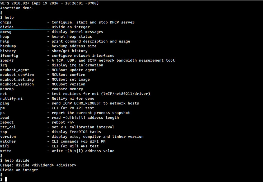
This is a very simple CLI command to perform integer division, as shown below.
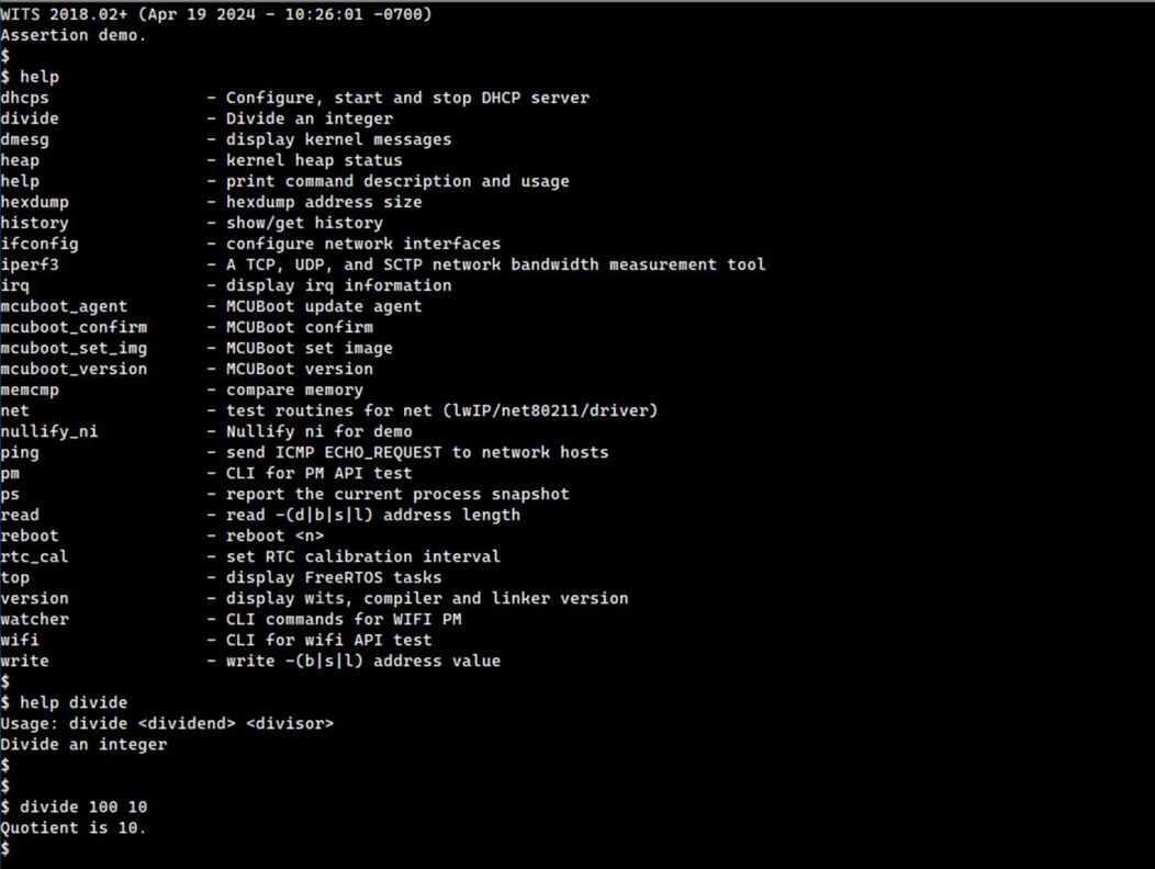
It throws an assertion failure when passing 0 as the divisor.
$ divide 100 0
WITS 2018.02+ riscv32-elf-gcc.gnu (2022-02-07_nds32le-elf-mculib-v5-86807094a2f) 10.3.0
[000005.735229] BOARD: tlsr_w91 QFN40 EVB V1.0
[000005.735371] VFS: filesystem devfs mounted onto /dev
[000005.737228] PINCTRL: pin controller tlsr_w91,pinctrl registered
[000005.737428] GPIO: tlsr_w91,pinctrl registered as /dev/gpio
[000005.737676] atcwdt: @0xf1300000, clk=32768
[000005.737873] WDT: atcwdt registered as /dev/watchdog
[000005.738206] PINCTRL: atcspi200-xip/cs request pin 11
[000005.738391] PINCTRL: atcspi200-xip/clk request pin 12
[000005.738543] PINCTRL: atcspi200-xip/mosi request pin 13
[000005.738705] PINCTRL: atcspi200-xip/miso request pin 14
[000005.738879] PINCTRL: atcspi200-xip/hold request pin 9
[000005.739045] PINCTRL: atcspi200-xip/wp request pin 10
[000005.739537] EFUSE: efuse-tlsr_w91 registered as /dev/efuse
[000005.739664] trng version : 5e5e0010
[000005.739817] TRNG: trng registered as /dev/trng
[000005.739922] pke version : 0x5e5e0010
[000005.781866] Use fixed MAC address: 64.f9.47.f0.01.20
[000005.782856] 263 usec elapsed in downloading MAC FW.
[000007.077269] Wlan PM ctx init done
[000007.078721] UART: atcuart.0 registered as /dev/ttyS0
[000007.078854] CONSOLE: add /dev/ttyS0
[000007.079249] UART: atcuart.1 registered as /dev/ttyS1
[000007.079362] SOC: tlsr_w91
[000007.079852] Use fixed BLE public address: 01.02.03.04.05.06
[000007.082093] ble phy init 35
[000007.082216] PM feature : 0x1d
[000007.082975] PM LS : 6500+1120=7620
[000007.083125] PM SL : 6500+7100=13600
[000007.083273] PM DS : 11500+12800=24300
[000007.083429] PM HB : 1655000+60000=1715000
[000007.083677] PINCTRL: atcuart.0/txd request pin 22
[000007.083829] PINCTRL: atcuart.0/rxd request pin 21 [000336.345105] BUG: assertion(divisor != 0), check_divide_by_zero() at 36
[000336.351793] sp:     0021cc10
[000336.354780] IRQ stack:
[000336.357243]   base: 0021b5b0
[000336.360236]   size: 00000800
[000336.363230] User stack:
[000336.365779] base: 0021bdc0
[000336.368772] size: 00000ff0
[000336.371767] 0021cc00: 0021cc10 00203be8 00000800 8008f094 a5a5a5a5 a5a5a5a5 a5a5a5a5 0aa5a5a5
[000336.380772] 0021cc20: a5a5a5a5 a5a5a5a5 8010a2c8 00000001 0000004b 00001880 0021cdd0 0021ce04
[000336.389719] 0021cc40: 00000001 00000000 00000003 00000003 0014d210 0021bdc0 80100000 0021cdb0
[000336.398597] 0021cc60: a5a5a5a5 a5a5a5a5 8010a2c8 00000001 ffffffff 8008e7d8 8010b558 8008f0dc
[000336.407617] 0021cc80: a5a5a5a5 a5a5a5a5 00206f34 0020f1c0 ffffffff 8008e7d8 8010b558 80088df0
[000336.416653] 0021cca0: a5a5a5a5 a5a5a5a5 8010b57c 00000024 ffffffff 00000064 00000000 8008e7d8
[000336.425610] 0021ccc0: ffffffff 0020d408 00000003 80098278 ca2ca324 00210d88 0020d3f8 00210f44
[000336.434588] 0021cce0: 00210f38 00210f3f 00210f43 00000000 00000000 00000000 00000000 00000000
[000336.443430] 0021cd00: 00000000 00000000 00000000 00000000 00000000 00000000 00000000 00000000
[000336.452193] 0021cd20: 00000000 00000000 00000000 00000000 00000000 00000000 00000000 00000000
[000336.460956] 0021cd40: 00000000 00000000 00000000 00000000 00000000 00000000 00000000 00000000
[000336.469719] 0021cd60: a5a5a5a5 a5a5a5a5 a5a5a5a5 a5a5a5a5 a5a5a5a5 80113f84 00210f38 8009865e
[000336.478765] 0021cd80: a5a5a5a5 0020d60c 00202c04 80098672 a5a5a5a5 0020d60c 00202c04 800ff402
[000336.487780] 0021cda0: a5a5a5a5 a5a5a5a5 a5a5a5a5 00000000 a5a5a5a5 a5a5a5a5 a5a5a5a5 a5a5a5a5
[000336.498464] PID  PR  STWM  S  TASK
[000336.505721]   1   3  532   X  init                           (0x21bdc0-0x21cdb0, 0x21c79c)
[000336.514696]   2   0  964   R  idle                           (0x20fc1c-0x210c10, 0x210b2c)
[000336.523662]   4   3  683   B  knetd                          (0x21d0d0-0x21dcc0, 0x21db7c)
[000336.532629]   3   5  193   B  ksofttimerd                    (0x20f798-0x20fb90, 0x20fabc)
[000336.541595]   7   3  303   B  rt_msg                         (0x221620-0x221c10, 0x221aec)
[000336.550561]   6   3  315   B  knet80211d/wlan0               (0x220d50-0x221340, 0x22123c)
[000336.559527]   8   7  48    B  ll                             (0x222ba0-0x222e10, 0x222d0c)
[000336.568489]   5   3  571   B  tlsr_wlan-wlan fast taskq      (0x21f730-0x220120, 0x22001c)
The information about the contents of the last console buffer, the contents of the user stack, and active tasks will also be displayed. For more information, see section Core Dumps.
The call flow that led to this particular assertion can also be identified by analyzing the dumped user stack contents with wits.dis and wits_rom.dis (if applicable), as shown in section Illegal Command Exception.
Stack Overflow
Overview
A stack overflow involves an accidental modification of stack memory and can occur for a variety of reasons, such as mishandling of pointers, task contention for the same data, incorrectly sized data structures, or incorrect memory release. This problem may manifest itself in a variety of symptoms, including system crash, operation suspension, heap memory leak, assertion failure, or performance degradation. Solving such problems usually requires a significant amount of time and a strategic approach using a variety of debugging tools and techniques. This document focuses specifically on stack overflows as the primary example of stack corruption.
A stack overflow occurs when a task or interrupt service routine overuses its allocated stack memory beyond its boundaries. This is functionally equivalent to disabling stack size limit enforcement during operation.
Despite its potential severity, a stack overflow may not immediately cause a crash, suspension, or assertion failure, as shown in the following example.
Stack Overflow Demo
The stack overflow in the application will be demonstrated by running the demo application. See section Demonstrate how to debug with tlsr9118-sdk to build and run the debugging demo.
There is a CLI command named print_string.
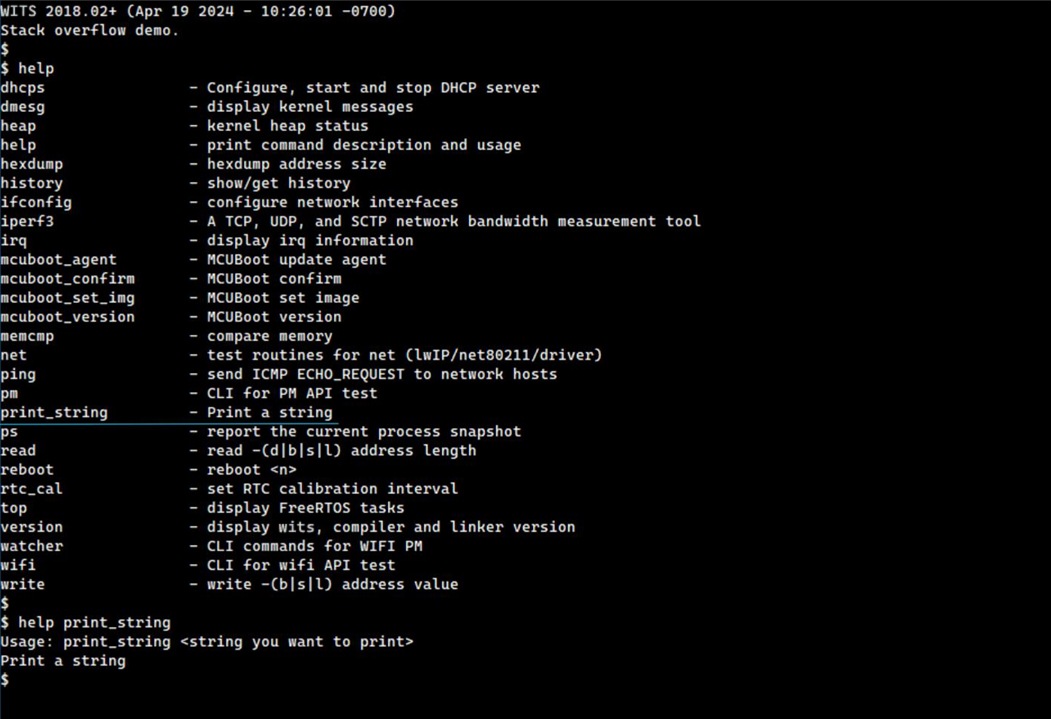
This is a very simple CLI command to print a given string to the UART console, as shown below.
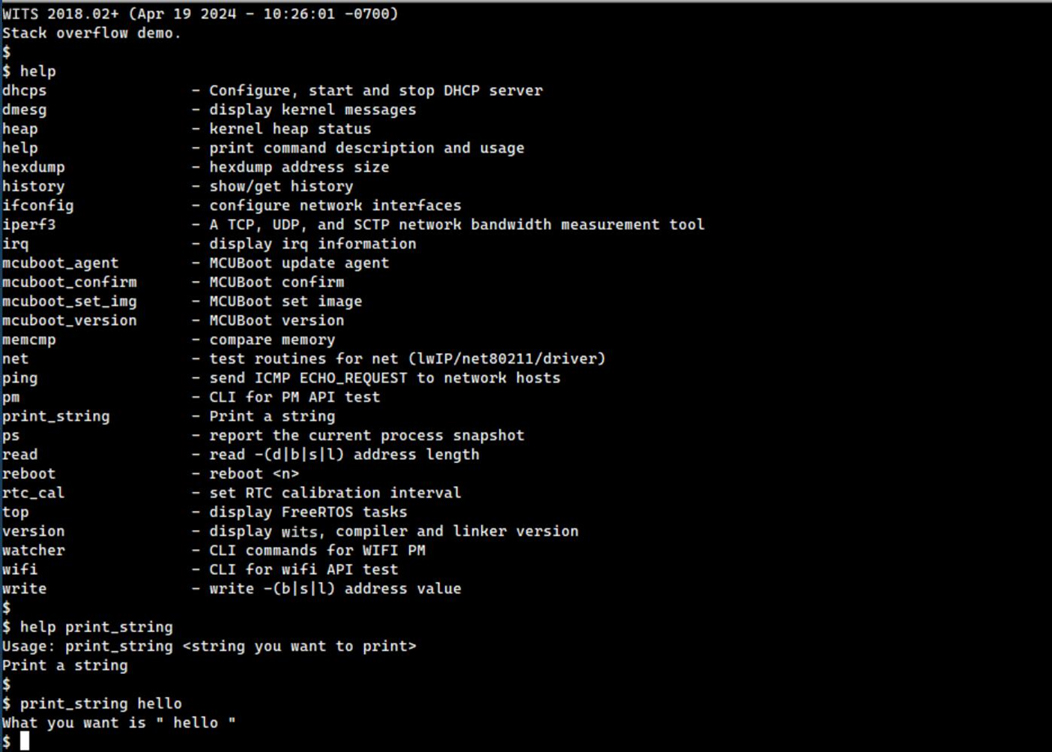
However, this demo application has major errors in its design.
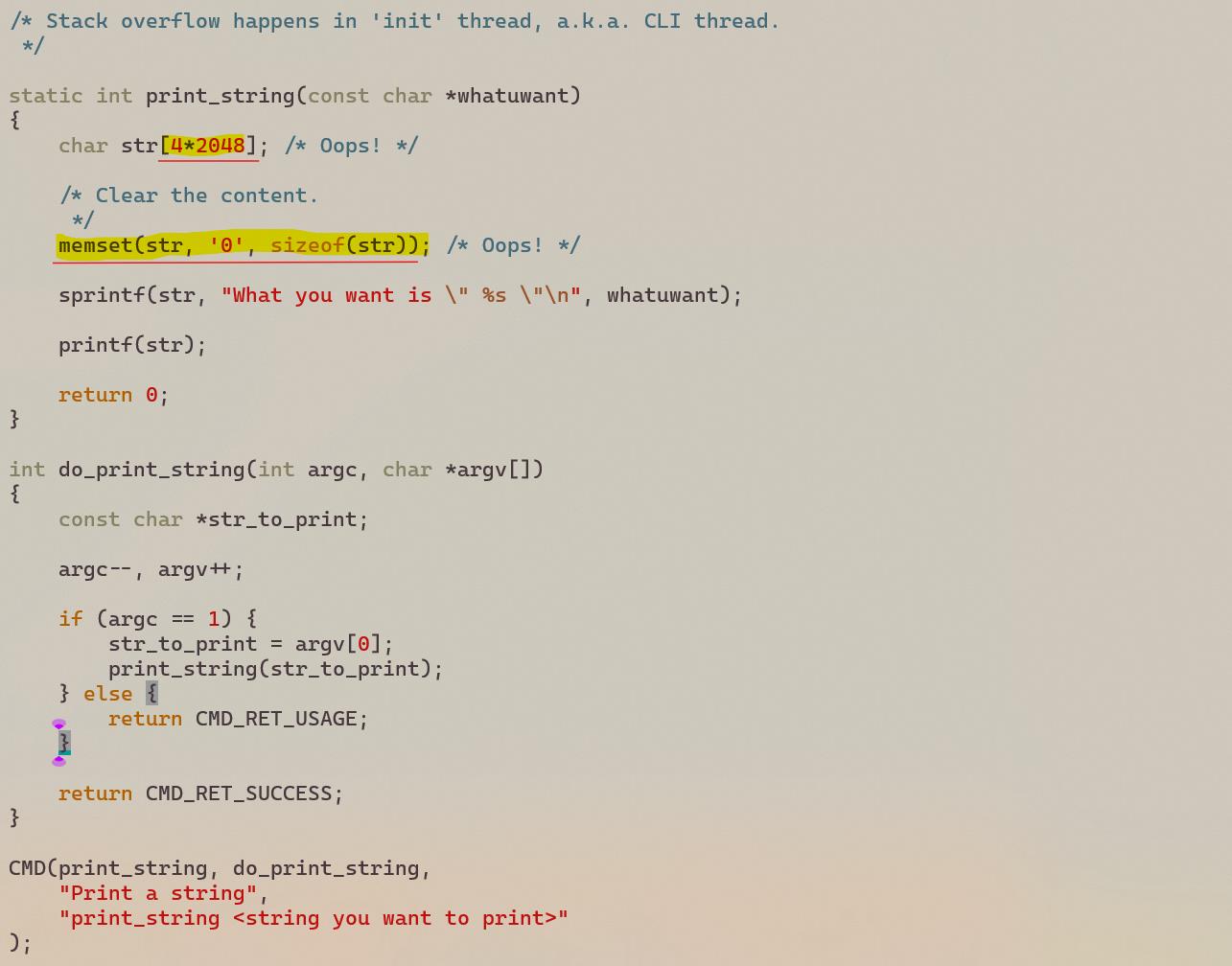
As shown above, the function print_string uses too much space from its caller's stack (the stack of the init task in this case).
As a result, the stack of the init task has been overflowed, even though the whole system seems to be running fine without any problems.
It can be verified in two different ways.
The first method is to run the ps command and check the STWM value.
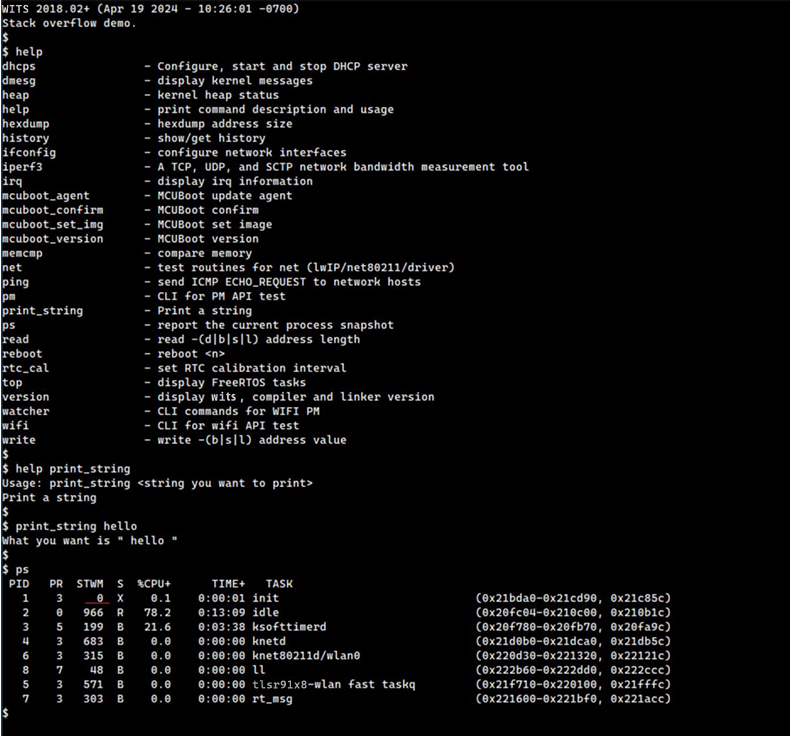
The STWM (i.e., Stack Watermark) for the init task now shows 0, which means that there is no free space left on the stack at some point.
Please be noted that the stack overflow cannot be detected relying on the last recorded stack pointer (0x21c85c in this case). As it can be seen, it is still legally located within the original stack space, between 0x21bda0 and 0x21cd90.
This is because the suffix of the function still returns to stack space and perform a pop up operation.
Secondly, directly inspect the memory area around the top of a particular stack (0x21bda0 in this case).
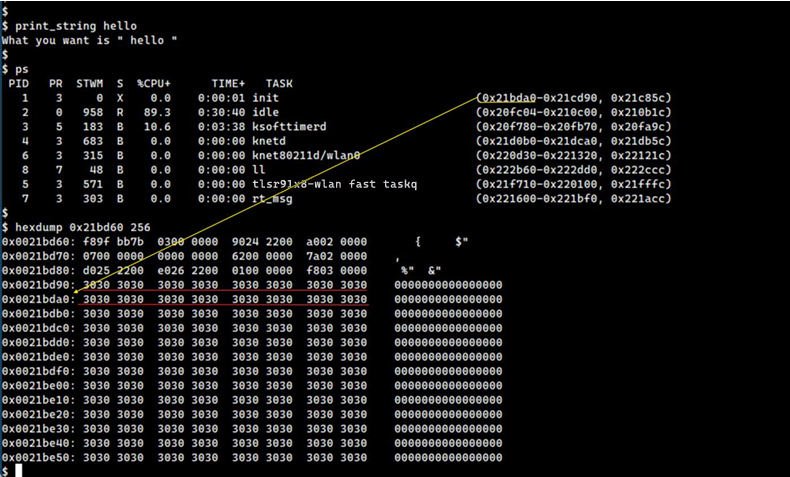
It can be proved that the stack has been overflowed.
It is worth noting that the stack memory will be filled with a specific byte pattern 0xa5 when the corresponding task is created.
This can be illustrated by looking at the upper boundary of the full stack.
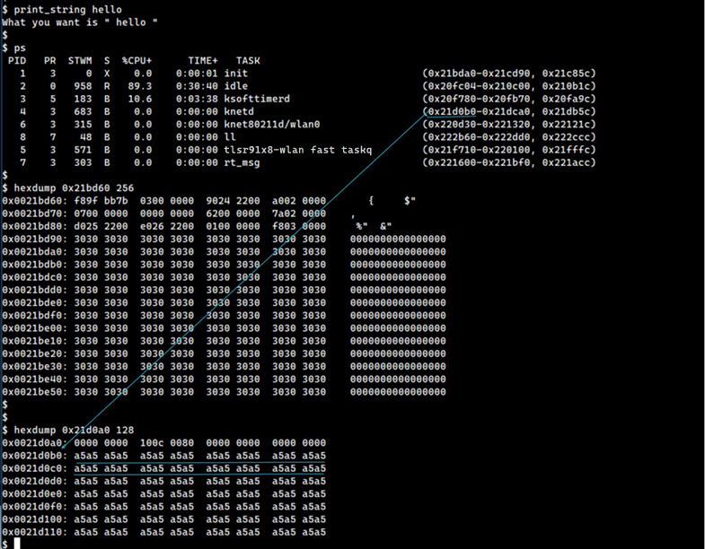
Therefore, seeing any data different from 0xa5 on the upper boundary of the stack proves that an overflow occurred.
In this case, as mentioned earlier, the entire system continues to operate without any apparent defects. This allows to access CLI command for further investigation.
However, if an immediate crash, suspension, or assertion failure occurs that prevents accessing the interactive CLI anymore, it is needed to use other methods to move on, such as connecting to the JTAG debugger to dump the relevant stack memory.
Memory Leak
Overview
The TLSR9118 SDK provides the following functions that allow user applications to allocate and free blocks of memory from a dynamic memory pool (i.e., the heap).
| Function(*) | Header File | Description |
|---|---|---|
| void *malloc(size_t sz) | <stdlib.h> | - Allocate a memory block of size sz bytes and return its starting address. - Return NULL if the passed size is 0. |
| void *zalloc(size_t sz) | <stdlib.h> | - Allocate a memory block of size sz bytes and return its starting address. - Returns NULL if the passed size is 0. - If successful, the contents of the newly allocated block will be cleared to 0 before returning. |
| void *calloc(size_t n, size_t sz) | <stdlib.h> | - Allocate a memory block of size n * sz bytes and return its starting address. - Return NULL if the passed size is 0. |
| void free(void *p) | <stdlib.h> | - Return a previously allocated memory block with a starting address of p to the system heap. - If p is NULL, no operation is performed. |
While user applications should be written carefully so as not to fail to free dynamic memory that has been used and is no longer needed, the TLSR9118 SDK provides a CLI command heap to help ensure this.
| CLI | Configuration | Purpose | Description |
|---|---|---|---|
| heap | - Command Line Interface - K -> Miscellaneous Utilities - D --> heap command - Enable by default |
now the overall heap usage Show:< etect heap memory leak over time - - |
br> Current Heap usage Maximum Heap usage since startup - Free Available heap space - Total Heap space size |
| heap check (*) | - Command Line Interface - D -> Miscellaneous Utilities al -> heap command - Kernel -> FreeRTOS kernel -> Memory -> Debug enabled malloc/free |
etect whether the boundary of a dynamically - C located memory block is overflowed bounda - S a an - I |
heck each allocated memory block in the system for ry overflow. pecifically check the header sentry mode of each llocated block, 0xcafe1234, d Tail Sentry Mode, 0xdeaf5678. f the check fails, show detailed information about the damaged block. |
| heap list (**) | - Command Line Interface - L -> Miscellaneous Utilities th -> heap command - I - Kernel o -> FreeRTOS kernel -> Memory -> Debug enabled malloc/free - Kernel -> FreeRTOS kernel -> Memory -> Record memory allocation function |
ist all memory blocks currently allocated from Sh e heap - Inde dentify unrecovered blocks across specific - perations and/or over time. - - - |
ow: x of block Name of owner's task Name of the function that allocates the block (if available) Starting address of block Block size |
Note
- The
heap checkcommand may be an alternative method of detecting dynamically allocated stack overflow, see section Stack Overflow. - Function names are available only if the function calls
mallocor its variants directly. If the function callskmallocor its variants, theheap listwill showkm-XXXXXXXX, where0xXXXXXXXXindicates the address of the next command that jumps tokmalloc, i.e., the return address, which enables inference of the caller's context via lookups inwits.disand/orwits_rom.dis. If the memory block is allocated from a function in the TLSR9118's internal ROM, the corresponding entry will showro-XXXXXXXX, where0xXXXXXXXXindicates the return address of the particularmalloccall.
The following shows an example of running these commands.
WITS 2018.02+ (Apr 21 2024 - 14:12:16 -0700)
Heap leak demo.
$
$ $ heap
Current:          31680 B
Maximum:          32272 B
Free:             270416 B
Total:            302096 B
$ $ heap check
Okay.
$
$ $ heap list
[ 0] (none)            ro-8008ef02        address  21de80  size  4096
[ 1] (none)            ro-8008ef10        address  21eec0  size  132
[ 2] init              _if_alloc          address  21ef80  size  428
[ 3] init              ro-0010a484        address  21f160  size  132
[ 4] init              ro-8008ef02        address  21f220  size  3072
[ 5] init              ro-8008ef10        address  21fe60  size  132
[ 6] init              km-0010f152        address  21ff20  size  48
[ 7] init              ro-00117e48        address  21ff90  size  10
[ 8] init              km-800906b6        address  21ffd0  size  24
[ 9] init              km-800906b6        address  220020  size  24
[ 10] init             km-0010f152        address  220070  size  48
[ 11] init             ro-00117e48        address  2200e0  size  14
[ 12] init             km-80093656        address  220130  size  40
[ 13] init             km-800891ec        address  220190  size  412
[ 14] init             spi_create_defa    address  220360  size  16
[ 15] init             km-0010f152        address  2203b0  size  48
[ 16] init             ro-00117e48        address  220420  size  11
[ 17] init             km-0010f152        address  220460  size  48
[ 18] init             ro-00117e48        address  2204d0  size  10
[ 19] init             km-800906b6        address  220510  size  24
[ 20] init             km-800891ec        address  220560  size  4696
[ 21] init             km-800891ec        address  2217f0  size  640
[ 22] init             km-0010e66c        address  221ab0  size  120
[ 23] init             ro-0010c052        address  221b60  size  2560
[ 24] init             ro-0010c060        address  2225a0  size  124
[ 25] init             _if_alloc          address  222650  size  428
[ 26] init             _if_alloc          address  222830  size  2336
[ 27] init             km-0010e66c        address  223190  size  120
[ 28] init             ro-0010c052        address  223240  size  1536
[ 29] init             ro-0010c060        address  223880  size  124
[ 30] init             ro-0011beaa        address  223930  size  8
[ 31] init             ro-0011beb8        address  223970  size  8
[ 32] init             ro-00117d74        address  2239b0  size  480
[ 33] init             ro-8008ef02        address  223bd0  size  1536
[ 34] init             ro-8008ef10        address  224210  size  132
[ 35] init             tlsr_wlan_init_pm    address  2242d0  size  320
[ 36] init             _if_alloc          address  224450  size  428
[ 37] init             _if_alloc          address  224630  size  16
[ 38] init             ro-00117d74        address  224680  size  12
[ 39] init             ifa_alloc          address  2246c0  size  132
[ 40] init             ro-00117d74        address  224780  size  12
[ 41] init             ifa_alloc          address  2247c0  size  132
[ 42] init             _if_alloc          address  2250c0  size  428
[ 43] init             _if_alloc          address  2252a0  size  16
[ 44] init             km-8010737a        address  224880  size  252
[ 45] init             km-0010f152        address  2249b0  size  48
[ 46] init             km-8010737a        address  224d20  size  252
[ 47] init             km-0010f152        address  224e50  size  48
[ 48] init             ro-00117e48        address  224ec0  size  11
[ 49] init             ro-00117e48        address  224a20  size  11
[ 50] init             ro-0010a484        address  224a60  size  212
[ 51] init             ro-0010a484        address  224b70  size  212
[ 52] init             ro-0010c052        address  2252f0  size  640
[ 53] init             ro-0010c060        address  224f00  size  124
[ 54] ll               km-800906b6        address  224c80  size  24
[ 55] init             km-800906b6        address  224fb0  size  24
[ 56] init             ro-0010a484        address  2255b0  size  340
[ 57] init             ro-0010a484        address  225740  size  340
[ 58] init             km-800906b6        address  225000  size  24
[ 59] init             ro-001179a0        address  225050  size  16
[ 60] init             ro-001179a0        address  2258d0  size  16
[ 61] init             ro-001179a0        address  225920  size  16
[ 62] init             ro-00117e48        address  225970  size  5
[ 63] init             ro-00117e48        address  2259b0  size  11
[ 64] init             ro-00117e48        address  2259f0  size  10
$
$
$ommand
Memory Leak in the Demo
The memory leaks in the application will be demonstrated by running the demo application. See section Demonstrate how to debug with tlsr9118-sdkto build and run the debugging demo. In addition to what is described here, two adjustments are required to build the demo application.
-
Select
Kernel -> FreeRTOS kernel -> Memory option -> Debug enabled malloc/free. -
Select
Kernel -> FreeRTOS kernel -> Memory option -> Record memory allocated function. -
(*) Deselect
Command line interface -> Command history.
(*) Enabling command history will use additional heap memory, which will unnecessarily cloud the discussion.
There is a set of CLI commands: save_string, purge_string and list_string.
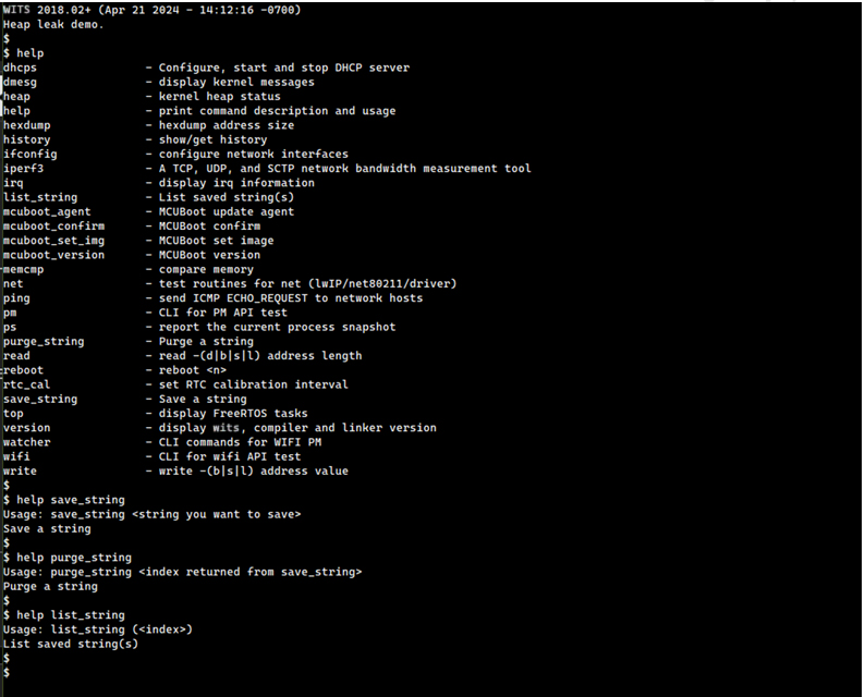
These commands are described in the following table, followed by examples of running them.
| Command | Description | Note |
|---|---|---|
| save_string | - Store string literals into an array. - Up - Return the index of the array where the string is stored |
to 10 strings can be saved. - Any extra strings will be discarded. |
| purge_string | - Remove the string literal corresponding to the given index from the array and reclaim the associated memory. | - |
| list_string | - List the contents of the string array. | - |
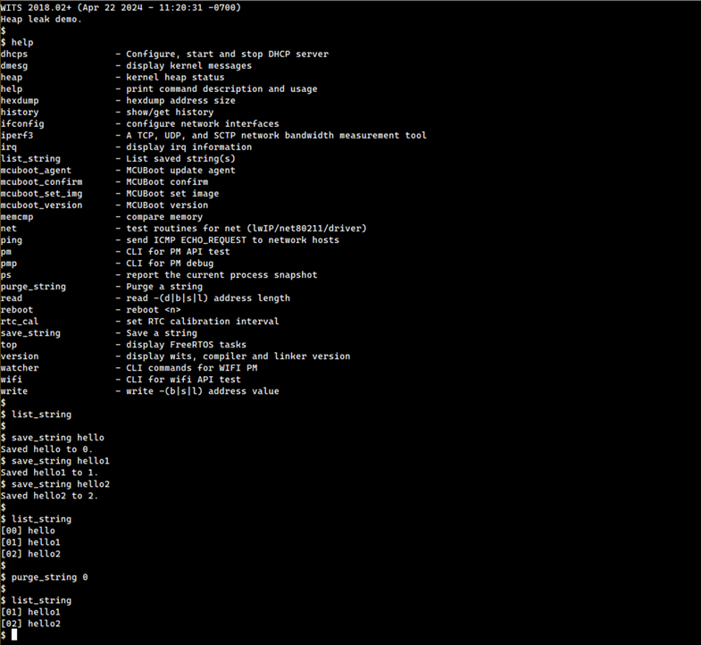
The demo application intentionally implants a bug, it causes a heap memory leak when we try to save more than the maximum number of strings (10 in this case).
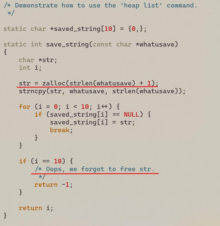
The following shows how to detect this error using the heap CLI command.
First, it can be seen that no leaks occur in the heap unless the maximum number of strings to be saved is reached.
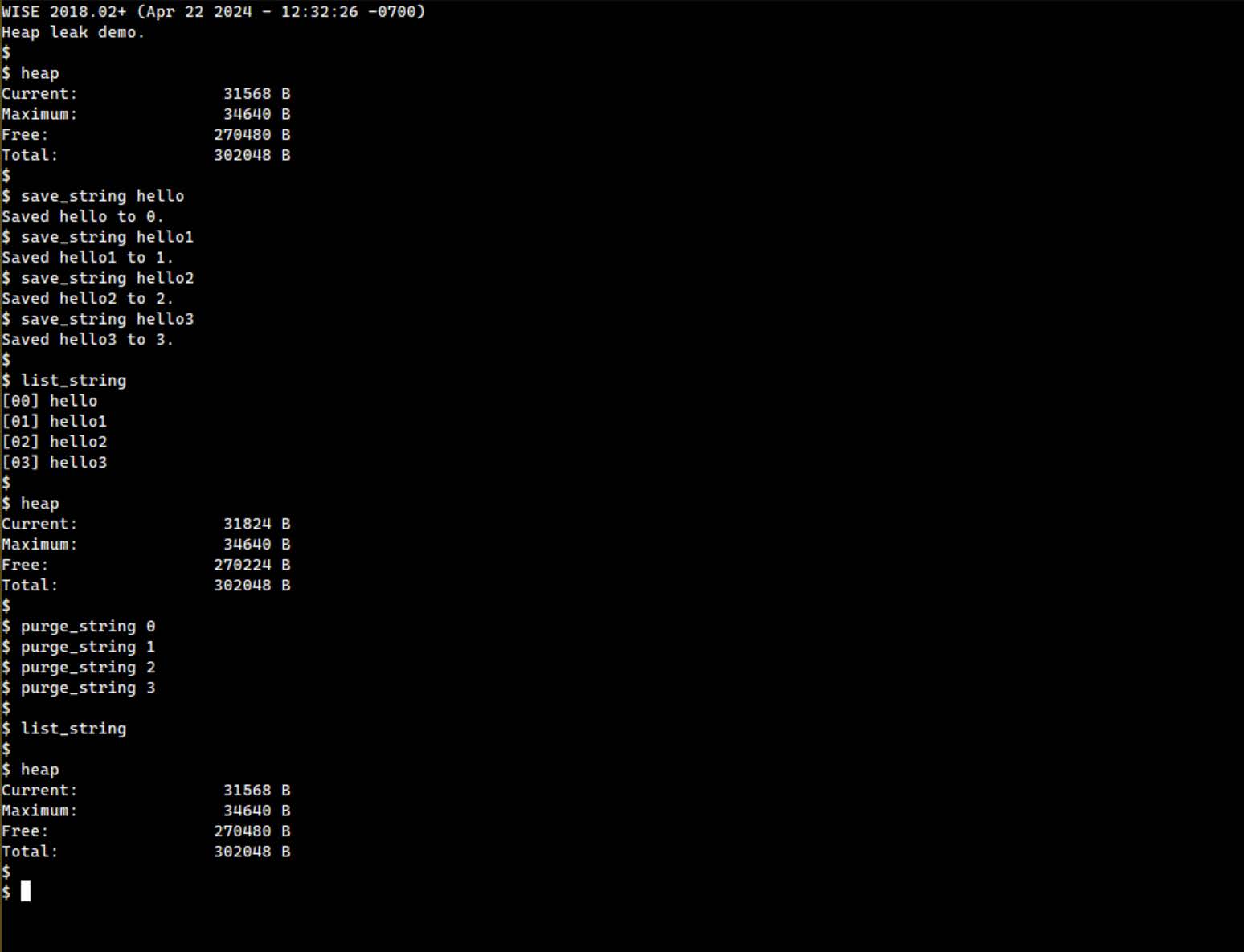
However, once the maximum number of strings to be saved is reached, the above error occurs as shown below.
$ list_string
$
$ heap
Current:       31568  B
Maximum:       34640  B
Free:          270480 B
Total:         302048 B
$
$
$ save_string hello
Saved hello to 0.
$ save_string hello1
Saved hello1 to 1.
$ save_string hello2
Saved hello2 to 2.
$ save_string hello3
Saved hello3 to 3.
$ save_string hello4
Saved hello4 to 4.
$ save_string hello5
Saved hello5 to 5.
$ save_string hello6
Saved hello6 to 6.
$ save_string hello7
Saved hello7 to 7.
$ save_string hello8
Saved hello8 to 8.
$ save_string hello9
Saved hello9 to 9.
$ save_string hello10
Couldn't save hello10 because there is no empty slot.
$ save_string hello11
Couldn't save hello11 because there is no empty slot.
$ save_string hello12
Couldn't save hello12 because there is no empty slot.
$ save_string hello13
Couldn't save hello13 because there is no empty slot.
$
$ list_string
[00] hello
[01] hello1
[02] hello2
[03] hello3
[04] hello4
[05] hello5
[06] hello6
[07] hello7
[08] hello8
[09] hello9
$
$ heap
Current:       32464  B
Maximum:       34640  B
Free:          269584 B
Total:         302048 B
$
$ purge_string 0
$ purge_string 1
$ purge_string 2
$ purge_string 3
$ purge_string 4
$ purge_string 5
$ purge_string 6
$ purge_string 7
$ purge_string 8
$ purge_string 9
$
$ list_string
$
$ heap
Current:       31824  B
Maximum:       34640  B
Free:          270224 B
Total:         302048 B
$
$
Since all 10 stored strings are cleared in the above example, the heap usage must be the same. However, the above results show that this is not the case, failing to free 4 unstorable strings due to the error mentioned above.
Comparing the free space in the heap can indicate the presence of some memory leaks, as shown above. However, it does not provide any further details.
To list all the unreclaimed memory blocks in the system help understand what is happening. The heap list command works for this.
$ heap list
[ 0] (none)           ro-8008f122          address   21deb0   size   4096
[ 1] (none)           ro-8008f130          address   21eef0   size   132
[ 2] init             _if_alloc            address   21efb0   size   428
[ 3] init             ro-0010a484          address   21f190   size   132
[ 4] init             ro-8008f122          address   21f250   size   3072
[ 5] init             ro-8008f130          address   21fe90   size   132
[ 6] init             km-0010f152          address   21ff50   size   48
[ 7] init             ro-00117e48          address   21ffc0   size   10
[ 8] init             km-800908d0          address   220000   size   24
[ 9] init             km-800908d0          address   220050   size   24
[ 10] init            km-0010f152          address   2200a0   size   48
[ 11] init            ro-00117e48          address   220110   size   14
[ 12] init            km-80093c10          address   220160   size   40
[ 13] init            km-80089214          address   2201c0   size   412
[ 14] init            spi_create_defa      address   220390   size   16
[ 15] init            km-0010f152          address   2203e0   size   48
[ 16] init            ro-00117e48          address   220450   size   11
[ 17] init            km-0010f152          address   220490   size   48
[ 18] init            ro-00117e48          address   220500   size   10
[ 19] init            km-800908d0          address   220540   size   24
[ 20] init            km-80089214          address   220590   size   4696
[ 21] init            km-80089214          address   221820   size   640
[ 22] init            km-0010e66c          address   221ae0  size   120
[ 23] init            ro-0010c052          address   221b90   size   2560
[ 24] init            ro-0010c060          address   2225d0   size   124
[ 25] init            _if_alloc            address   222680   size   428
[ 26] init            _if_alloc            address   222860   size   2336
[ 27] init            km-0010e66c          address   2231c0   size   120
[ 28] init            ro-0010c052          address   223270   size   1536
[ 29] init            ro-0010c060          address   2238b0   size   124
[ 30] init            ro-0011beaa          address   223960   size   8
[ 31] init            ro-0011beb8          address   2239a0   size   8
[ 32] init            ro-00117d74          address   2239e0   size   480
[ 33] init            ro-8008f122          address   223c00   size   1536
[ 34] init            ro-8008f130          address   224240   size   132
[ 35] init            tlsr_wlan_init_pm      address   224300   size   320
[ 36] init            _if_alloc            address   224480   size   428
[ 37] init            _if_alloc            address   224660   size   16
[ 38] init            ro-00117d74          address   2246b0   size   12
[ 39] init            ifa_alloc            address   2246f0   size   132
[ 40] init            km-801079f4          address   2247b0   size   252
[ 41] init            km-0010f152          address   2248e0   size   48
[ 42] init            _if_alloc            address   2250f0   size   428
[ 43] init            _if_alloc            address   2252d0   size   16
[ 44] init            ro-00117d74          address   225320   size   12
[ 45] init            ifa_alloc            address   225360   size   132
[ 46] init            ro-00117e48          address   224950   size   11
[ 47] init            ro-0010a484          address   224990   size   212
[ 48] init            km-801079f4          address   225d60   size   252
[ 49] init            km-0010f152          address   225e90   size   48
[ 50] init            ro-00117e48          address   225f00   size  11
[ 51] init            ro-0010a484          address   224aa0   size   212
[ 52] init            ro-0010c052          address   224bb0   size   640
[ 53] init            ro-0010c060          address   224e70   size   124
[ 54] ll              km-800908d0          address   224f20   size   24
[ 55] init            km-800908d0          address   224f70   size   24
[ 56] init            ro-0010a484          address   225420   size   340
[ 57] init            ro-0010a484          address   2255b0   size   340
[ 58] init            km-800908d0          address   224fc0   size   24
[ 59] init            ro-001179a0          address   225010   size   16
[ 60] init            ro-001179a0          address   225060   size   16
[ 61] init            ro-001179a0          address   225740   size   16
[ 62] init            save_string          address   225a10   size   8
[ 63] init            save_string          address   225a50   size   8
[ 64] init            save_string          address   225a90   size   8
[ 65] init            save_string          address   225ad0   size   8
$
It was found that there were 4 memory blocks that were not reclaimed when they should have been.
While this example may seem overly artificial, using the heap and heap list commands will greatly assist in solving more difficult memory leaks.
Customer Demonstration Guide
Overview
This section introduces the customer demonstration modules. In the customer_demo directory, sample code for each module is provided to help users modify and develop further based on their specific needs.
In addition to the CLI command verification methods described in previous sections, these sample codes demonstrate how to call SDK interfaces to implement specific functions. For detailed step-by-step instructions, precautions, and documentation for each example, please refer to the corresponding .md files in the SDK examples folder.
Customer Demonstration List
adc_demo
This demonstration shows how to use the on-chip ADC module to convert analog voltage signals into digital values.
Common Application Scenarios:
- Battery voltage detection: Reads the voltage to calculate remaining battery capacity.
- Sensor reading: Reads data from analog output sensors such as photoresistors and thermistors.
- Analog audio input: Simple microphone signal acquisition.
gpio_demo
This demonstration shows how to configure GPIO pins for output mode and control their high and low output levels.
Common Application Scenarios:
- LED control: Controls LED blinking.
- Flow control pins: Controls communication flow control for peripheral interfaces via GPIO levels.
i2c_demo
This demonstration shows how to configure GPIO as I2C interfaces (SCL and SDA) and implement data read/write timing in master mode.
Common Application Scenarios:
- Memory read/write: Communicates with external EEPROMs (such as the AT24C02).
- Sensor communication: Reads data from temperature and humidity sensors (such as the SHT30) and accelerometers (such as the MPU6050).
- Peripheral control: Controls touchscreen chips or I/O expansion chips.
spi_demo
This demonstration shows how to use the SPI interface for high-speed synchronous data transmission, including configuration of clock polarity, phase, and rate.
Common Application Scenarios:
- Display Driver: Drives TFT LCD or OLED displays, suitable for high-speed scenarios such as screen refresh.
- External Storage: Reads and writes external NOR Flash or NAND Flash.
- High-Speed Communication: Exchanges large amounts of data with another MCU.
uart_demo
This demonstration shows how to configure the baud rate, data bits, and stop bits, and perform transmission and reception of characters/strings (supporting both polling and interrupt modes).
Common Application Scenarios:
- Debug Logging: Implements
printffunctionality to output debug information to a terminal. - Command Interaction: Implements a CLI (Command-Line Interface) to control the device via serial commands.
- Module Communication: Communicates with external modules such as GPS modules, fingerprint modules, or wireless modules.
pwm_demo
This demonstration shows how to configure a timer to output a PWM waveform with adjustable frequency and duty cycle on a specified pin.
Common Application Scenarios:
- Lighting Control: Adjusts LED brightness or implements breathing light effects.
- Motor Control: Controls the speed of DC motors or the angle of servo motors.
- Audio Output: Drives a passive buzzer to generate tones of different frequencies.
bledistr_demo
This demonstration shows how to use a Bluetooth module to retrieve an AP’s SSID and password for network connectivity.
Common Application Scenarios:
- IoT or AI-based products: Obtains AP information to enable successful network connection.
sapdistr_demo
This demonstration shows the chip operating as a SoftAP to receive the SSID and password from a STA and establish a network connection.
Common Application Scenarios:
- IoT or AI-based products: Obtains AP information to enable successful network connection.
audio_demo
This demonstration shows how to configure the codec module via I2C and transfer audio data via I2S. This demonstration also provides usage examples for audio data transmission based on HTTP/MQTT, and includes a simple state machine for audio hardware control and audio data management.
Common Application Scenarios:
- HTTP Audio Playback: Retrieves MP3 audio files over HTTP and plays them locally.
- Audio Playback and Capture: Supports audio playback and capture scenarios.
- MQTT Audio Transfer: Supports audio data download and upload over MQTT.
pm_uart_demo
This demonstration shows the use of UART in low-power mode. Through PM interfaces and UART task control, the UART function remains operational after the chip wakes up from sleep. Typically, the peer UART device is required to wake up the chip via a GPIO signal before transmitting data.
Common Application Scenarios:
- Low-Power Products: Suitable for battery-powered or passive devices that require switching between active and low-power states.
http_client_demo
This demonstration shows the GET and POST data operations after connecting to a specified HTTP server.
Common Application Scenarios:
- IoT or AI-based products: Suitable for command control, file retrieval, and key information acquisition.
mqtt_client_demo
This demonstration shows the MQTT publish and subscribe data operations after connecting to a specified server.
Common Application Scenarios:
- IoT or AI-based products: Suitable for command control, file retrieval, and key information acquisition.