telink_zigbee_sdk Get Started
Overview
About this document
This document helps you quickly set up the IDE of telink_zigbee_sdk, obtain the SDK, build the project, and successfully run your first example. To read this document, you need to have a basic understanding of C language and embedded development.
Applicable scope
telink_zigbee_sdk is applicable to Telink's TL321x, TL323x, TLSR921x and other SoC series:
Notes
For detailed information on complete and accurate chip series, corresponding EVBs, development platforms, toolchain versions, and SDK versions, refer to the latest Release Notes.
Preparation
Hardware checklist
| Hardware | Description |
|---|---|
| PC | Windows 10/11 / Linux / macOS |
| EVB | Select the appropriate Evaluation Board (EVB) based on the Release Notes |
| Programmer | Programmer V3 |
| USB cable | Connect your PC and the programmer |
| Dupont wire | Connect the EVB and the programmer |
For physical hardware, refer to the section Connect the hardware.
Software checklist
| Software | Description |
|---|---|
| IDE | Telink VS Code Extension / Telink IoT Studio |
| Toolchain | Select the appropriate toolchain based on the EVB. For details, see Release Notes |
| Programmer software | Burning and Debugging Tool (BDT) |
| SDK | GitHub / Gitee |
Choose the IDE
telink_zigbee_sdk supports the following two IDEs:
Choose one based on your development habits. Both methods do not require simultaneous installation.
Telink VS Code Extension
Install VS Code
Before installing, make sure your computer has the latest version of Visual Studio Code. The updates to Telink VS Code Extension are based on the latest version of the VS Code. If the version is not the latest, it may not work properly or have abnormal functionality.
Install Telink VS Code Extension
- Launch VS Code.
- Click the Extensions icon in the left sidebar, or press Ctrl+Shift+X.
- Search for Telink.
- Find Telink Development Tool in the search results and click Install.
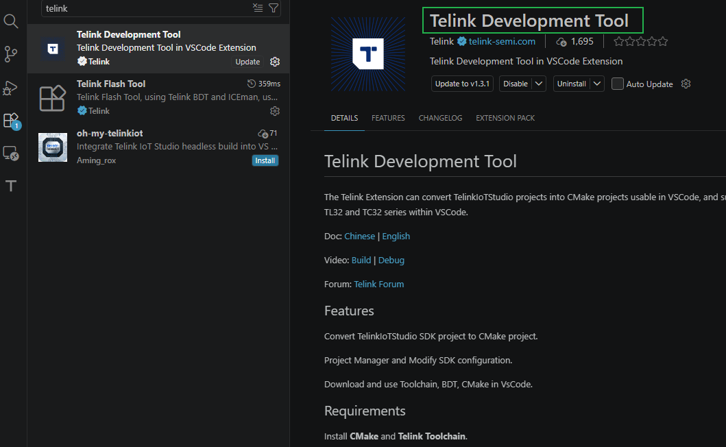
After installation, the Telink DEVELOPMENT icon appears in the left sidebar of VS Code.
Install the toolchain
In Telink VS Code Extension, download the compiler toolchain and auxiliary tools on demand via the built-in manager.
-
In the Telink DEVELOPMENT view, expand the DEVELOPMENT TOOLS tree menu.
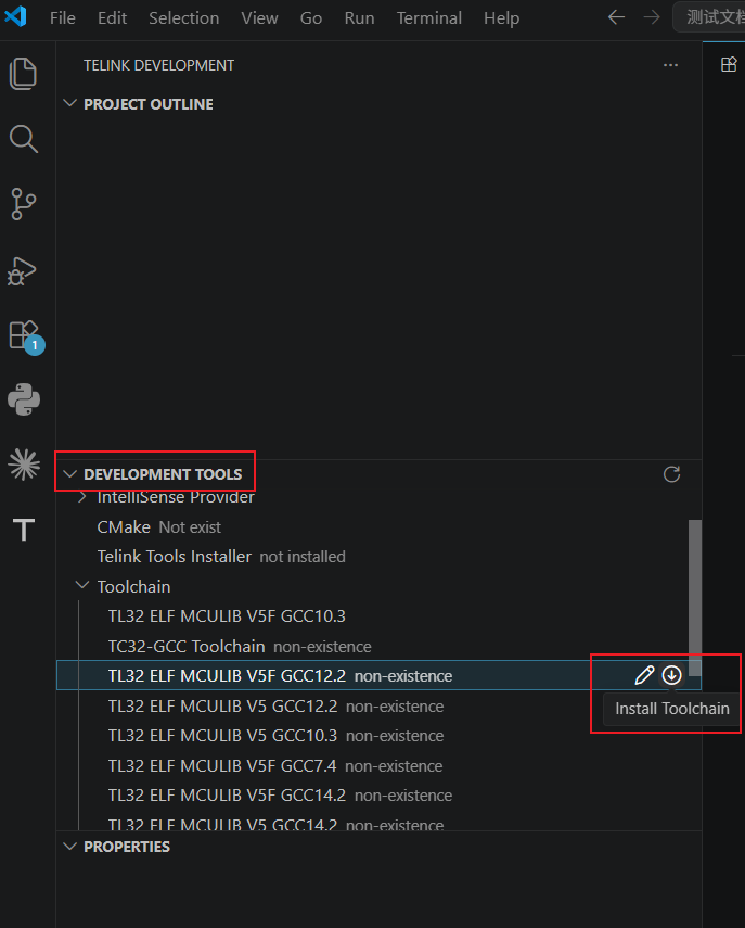
-
Click the toolchain you need, then click Install Toolchain on the right.
-
After successful installation, a corresponding completion notification pops up in the bottom right corner of the VS Code window.

Note
If you want to use the toolchain in the command line, right-click and select Open Terminal from the pop-up menu.
Install auxiliary tools
In the tool list, select CMake, right-click, and select Install from the pop-up menu.
Validate the IDE and the dependencies
After installation, follow the steps to validate whether Telink VS Code Extension has been installed successfully:
- Launch VS Code and confirm the software opens normally and that there are no error messages during startup.
- In the left sidebar, confirm the Telink icon appears and click it to enter the Telink DEVELOPMENT view.
- In the DEVELOPMENT TOOLS tree menu, confirm that the installed toolchain shows Installed status on the right.
- At the same time, confirm that the auxiliary tool CMake also shows that it has been installed.
If all the above checks are normal, Telink VS Code Extension and its dependencies have been successfully installed and configured, and you can start downloading the SDK to begin SDK development.
Telink IoT Studio
Download and install Telink IoT Studio
Download the installation package corresponding to your operating system. The demonstration uses Windows as an example:
- Windows : TelinkIoTStudio_V2025.2.zip
- Linux : Telink_IoT_Studio_2025.2_Installer.run
Install Telink IoT Studio:
Windows:
- Extract the .zip file, run TelinkIoTStudio_V2025.2.exe, and follow the wizard to complete the installation.
- After installation, run TelinkIoTStudio Updater.exe to update the components.
Linux:
- Grant installation package execution permissions to the runtime environment.
- Run Telink_IoT_Studio_2025.2_Installer.run and follow the prompts in the terminal to complete the installation.
Toolchain description
Telink IoT Studio offers an all-in-one standalone installation package with all the components required built in, eliminating the need for additional toolchain installation. All required toolchains and auxiliary tools are installed synchronously when installing the IDE. By clicking Telink in the top menu bar, open the toolchain's Cygwin Shell.
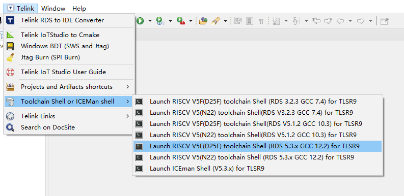
Validate the IDE and the dependencies
After installation, follow the steps below to validate that Telink IoT Studio has been successfully installed.
Validate the IDE:
- Launch Telink IoT Studio and confirm that it loads normally and displays the main interface, with no error messages during startup.
- Click the top menu bar Telink and confirm that toolchain entries such as Cygwin Shell in the dropdown menu open normally.
If the above conditions are met, Telink IoT Studio has been successfully installed and configured.
Validate the dependencies:
SDK compilation and version management rely on the following tools. Run the corresponding commands in the terminal to validate.
| Dependencies | Validation commands | Expected versions |
|---|---|---|
| Python | python --version or python3 --version |
Python 3.8 or higher (recommended 3.8~3.12) |
| Git | git --version |
Git 2.30 or higher |
After confirming that all the above dependencies have been correctly installed, you can start downloading the SDK and begin SDK development.
Get and import the SDK
This chapter explains how to obtain the SDK, its top-level directory structure, and how to import SDK projects into the IDE.
Download the SDK
Download the latest SDK via GitHub / Gitee or run the following git clone command to clone the repository locally:
git clone https://github.com/telink-semi/telink_zigbee_sdk
SDK directory overview
| Directory | Description |
|---|---|
apps/ |
Examples |
platform/ |
Chip-supported platforms |
proj/ |
Common functions, adaptation layer drivers |
stack/ |
Protocol stack |
build/ |
Project build directory |
tools/ |
Script tools |
For the full directory structure and the function of each directory, refer to Zigbee SDK Developer Manual.
Import the project
Depending on the IDE you choose, import the project into VS Code or import the project into Telink IoT Studio.
Import the project into VS Code
After importing the telink_zigbee_sdk project, a conversion operation is required before it can be used in the VS Code environment.
- Click File -> Open Folder... in the VS Code menu bar, select the root directory of the project, and load it.
-
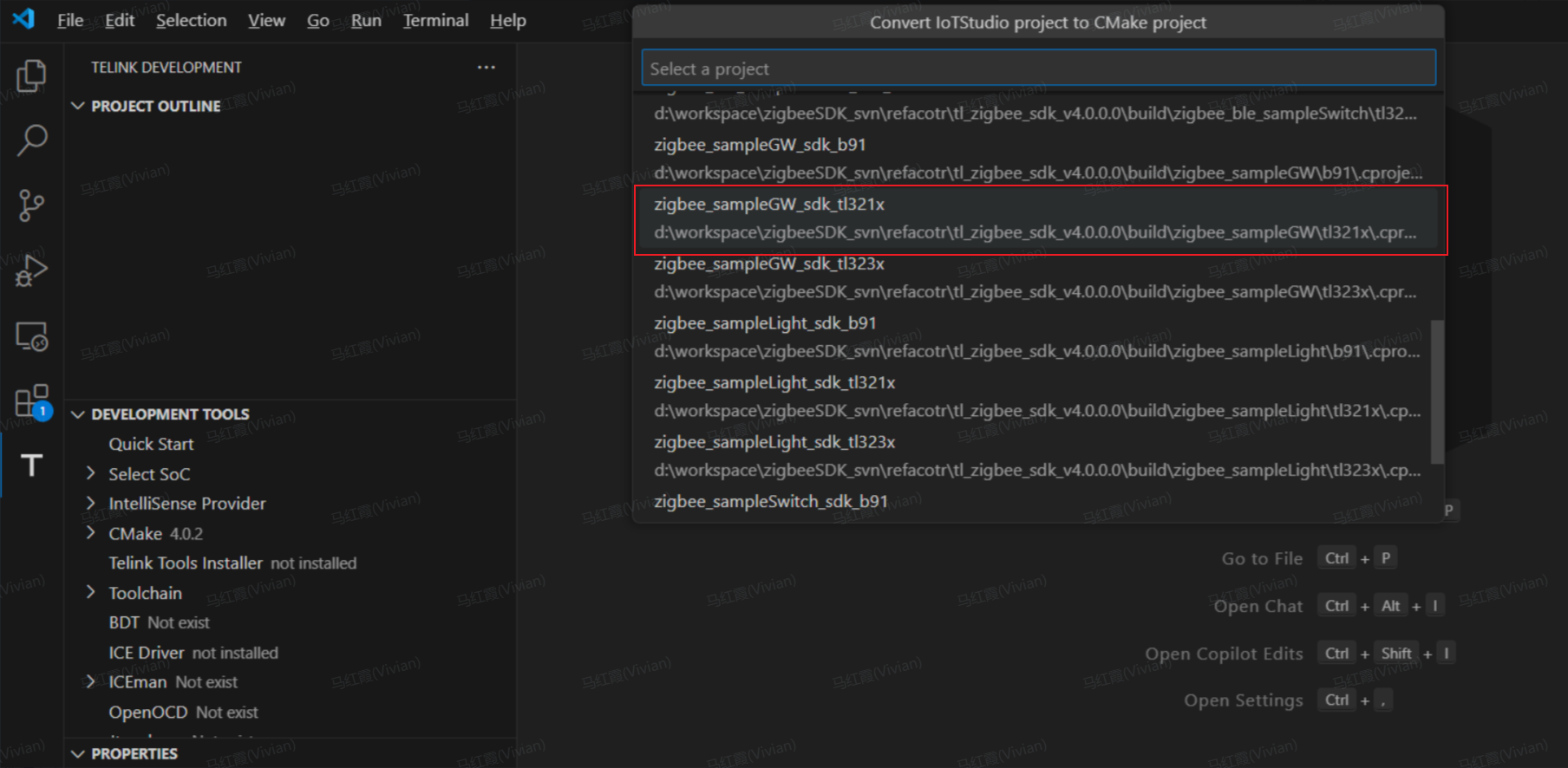
Click the Telink icon in the left sidebar to enter the Telink Extension view, and click Convert Telink Project next to PROJECT OUTLINE.
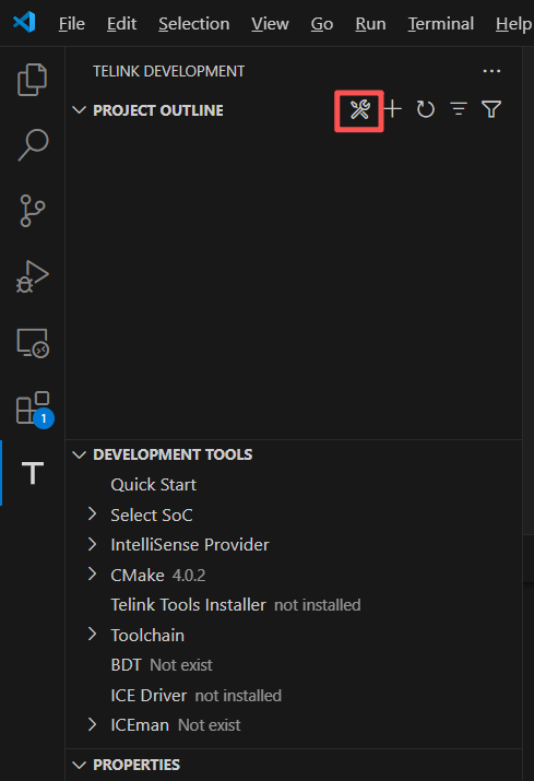
-
In the search bar, select the chip series you need to convert to a Telink VS Code Extension project.
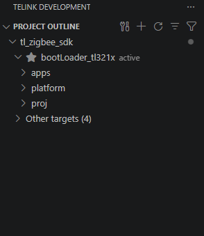
After successfully importing the project, compile it in VS Code.
Import the project into Telink IoT Studio
If you choose to use Telink IoT Studio as your IDE, follow the steps to import the project:
- Click File -> import in the top menu bar.
-
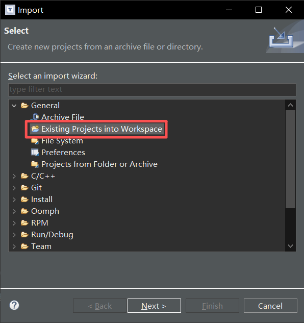
In the pop-up dialog box, expand General directory, select Existing Projects into Workspace, and click Next.
-
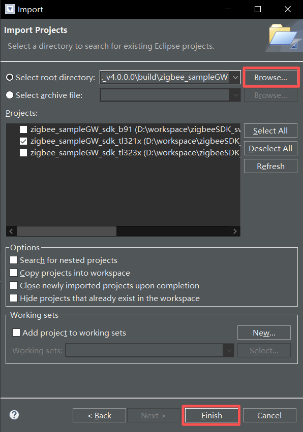
Click Browse, navigate to the build folder, select the corresponding project, and click Finish to complete the import.
After successfully importing the project, compile it in Telink IoT Studio.
Compile and run the first example
This chapter guides you from selecting examples and code compile to final programming and execution.
Select the example
It is recommended to use the officially provided sampleGW as the first engineering example. This example features LED indicators, allowing quick verification of firmware flashing and operation.
This example uses the TL321x Dongle for demonstration. If you only have an EVK, modify the board parameter in app_cfg.h as shown below.
#define BOARD BOARD_TL321X_EVK//BOARD_TL321X_DONGLE
For more examples, check the directory ...\telink_zigbee_sdk\tl_zigbee_sdk\apps.
Compile the project
Compile the project in VS Code
-
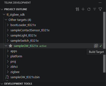
In the left sidebar of VS Code, find PROJECT OUTLINE, and select the project to compile and its corresponding Target.
-
Click the build button on the right to compile.
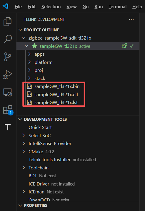
After compilation, output files (
.elf,.bin,.ls) are generated in the ...\telink_zigbee_sdk\tl_zigbee_sdk\cmake_builds\tl_zigbee_sdk\TL32_ELF_MCULIB_V5_GCC12_2 folder, withELFformat files used for debugging andBINfiles for programming.Compilation successful, seeing a similar output:
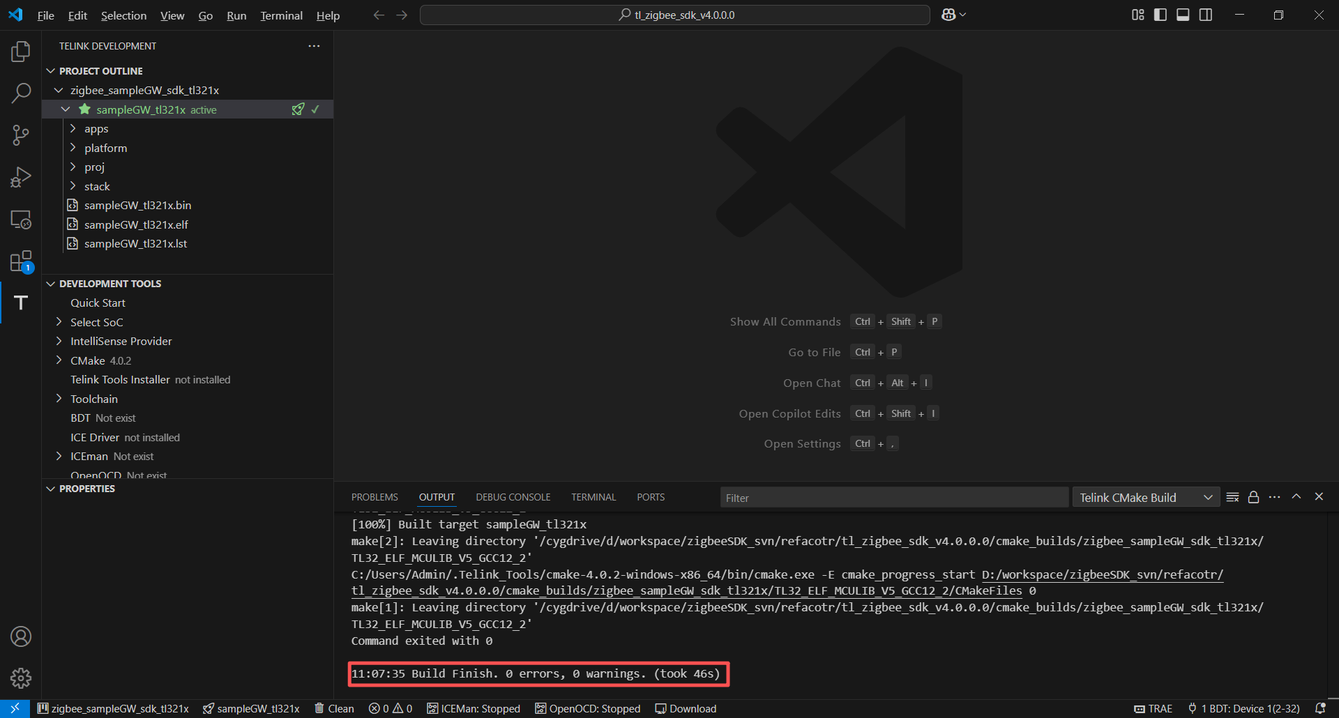
Compile the project in Telink IoT Studio
- In the Project Explorer on the left, select the project you want to compile.
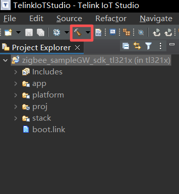
- Click the small dropdown arrow next to the Build button (hammer icon) on the top toolbar.
-
Select the configuration you want to compile from the dropdown menu, and the system begins compiling.
-
Observe the console output; if there are no error messages and Build Finished is displayed, the compilation is successful.
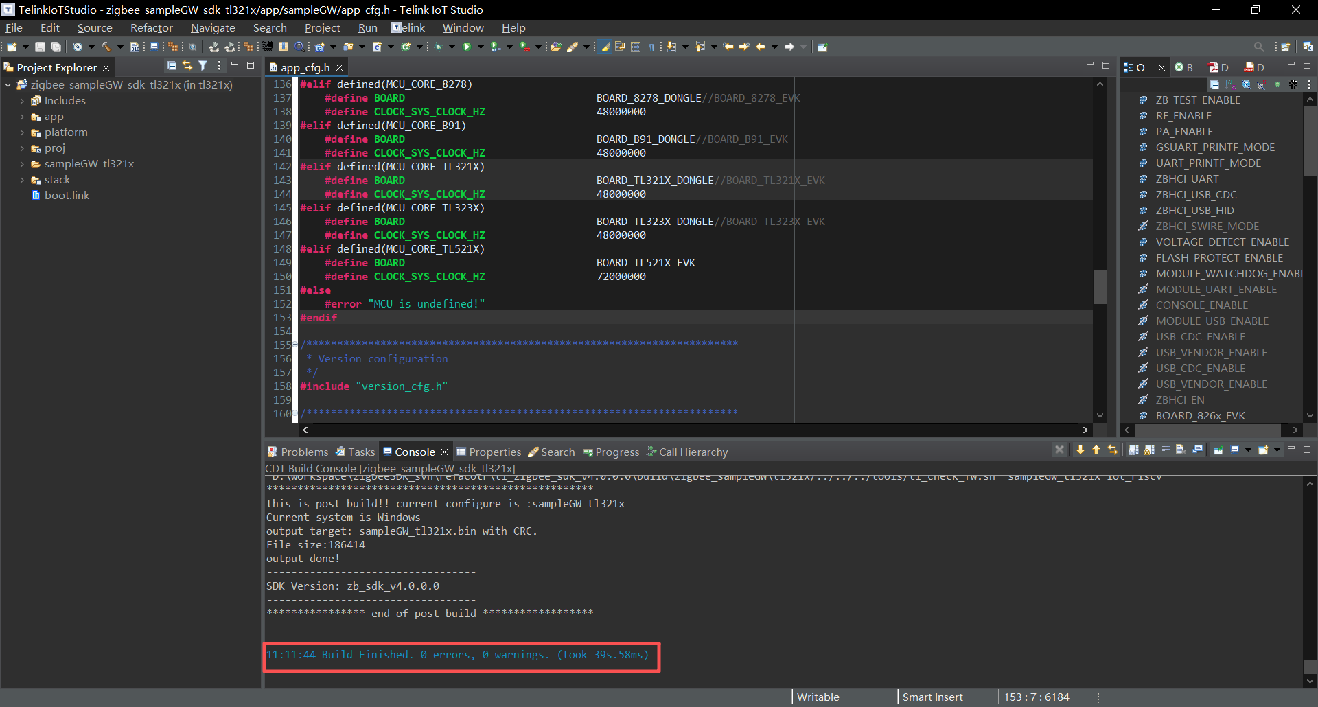
Taking the TL321x platform sampleGW as an example, the compiled bin file is stored in the ...\telink_zigbee_sdk\tl_zigbee_sdk\build\iot_riscv_tl321x\sampleGW_tl321x folder, with ELF format files used for debugging and BIN files for programming.
Flash the firmware
Firmware flashing is performed by the BDT.
Step 1: Connect the hardware
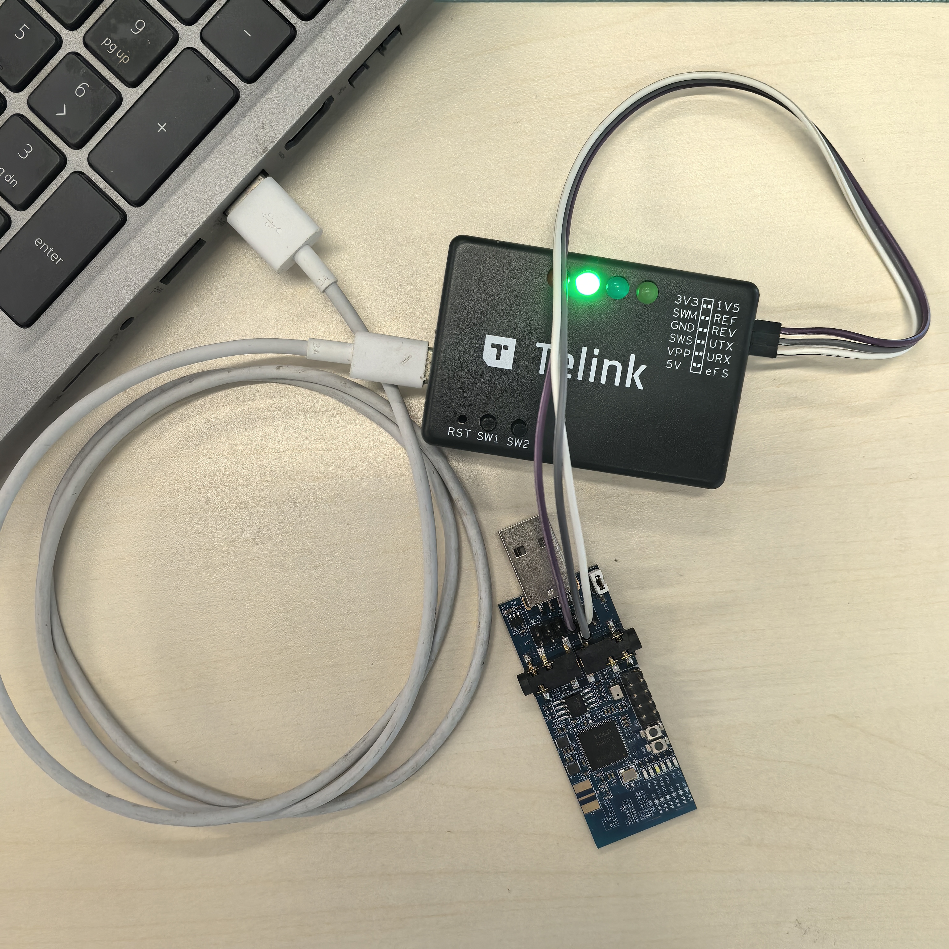
Before using the BDT, connect the PC, the programmer, and the target board:
- PC ↔ Programmer: Connect via USB cable. If the green indicator light on the programmer stays on, it indicates the programmer has been successfully recognized by the PC.
-
Programmer ↔ Target board: Connect using the Dupont wire:
- Power cable: VCC ↔ VCC; GND ↔ GND
- Data cable (Single-wire SWM bus): Connects the programmer's SWM pin to the target board's SWS (Swire) pin.
Step 2: Install the BDT
-
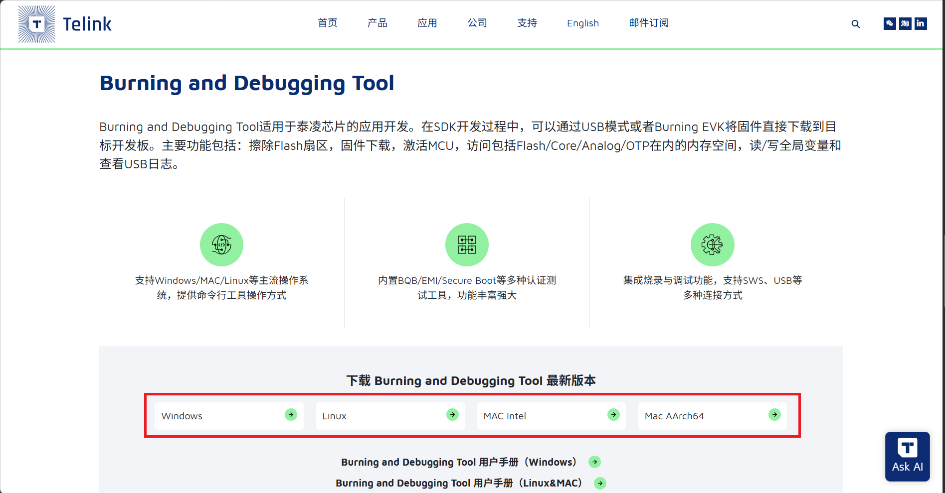
Download BDT.
Visit Telink Developer Center - Development Tools and download the corresponding toolkit according to your operating system.
-
Extract the toolkit.
The BDT tool is a green no-installation version that can be used after extraction.
Take Windows as an example:
-
Extract the downloaded toolkit to a custom path, such as C:\Telink\BDT.
-
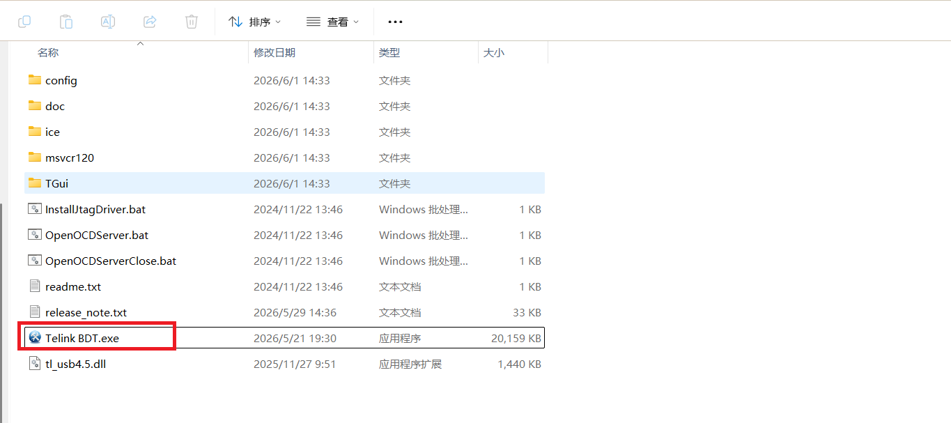
Enter the extracted release directory, for example C:\Telink\BDT\release_v5.9.2.
-
Double-click and run Telink BDT.exe to launch the tool.
-
-
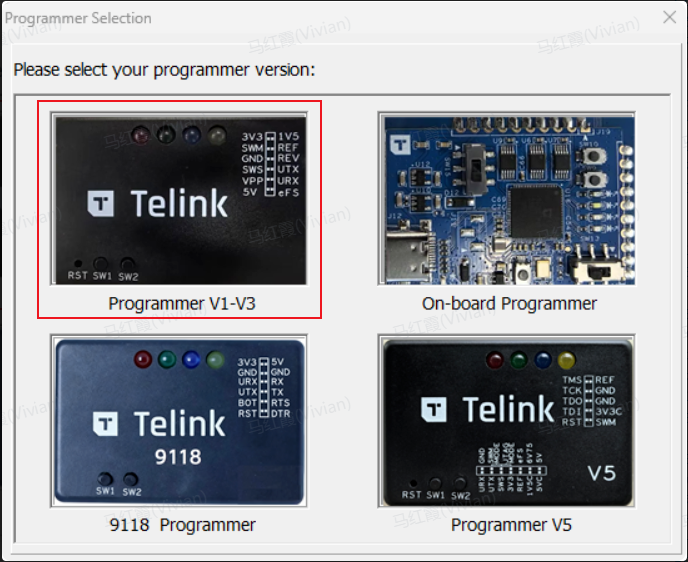
Choose the applicable version based on the compatibility with the chip series
Telink provides four versions of programmers (Programmer). When launching the BDT interface, it is recommended to select the Programmer V1.0 ~ V3.0 programmer version.
Step 3: Flash the firmware
-
Detect the device.
Open the BDT. Before firmware flashing, ensure the tool has detected the programmer, as shown in the figure below.
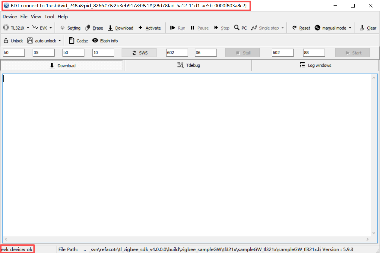
- If the BDT does not find the device, click Refresh to view available devices.
- If the BDT finds multiple devices, all of them will be listed. After clicking Refresh, the first device is activated by default, and you can also manually switch target devices from the list.
-
Configure and flash
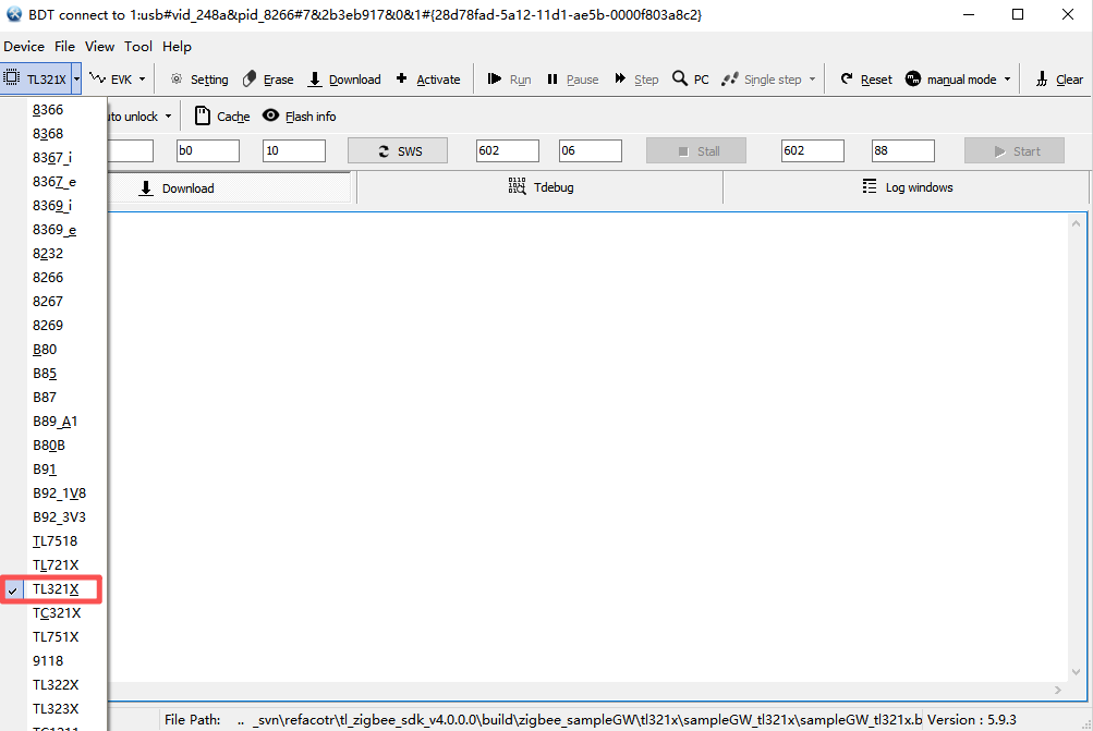
a. Select the chip series of the target board.
In the dropdown menu at the top, select the target chip for your development board, such as TL321x.
Note
- B91: Refers to TLSR921x and TLSR951x series chips;
- B92: Refers to TLSR922x and TLSR952x series chips.
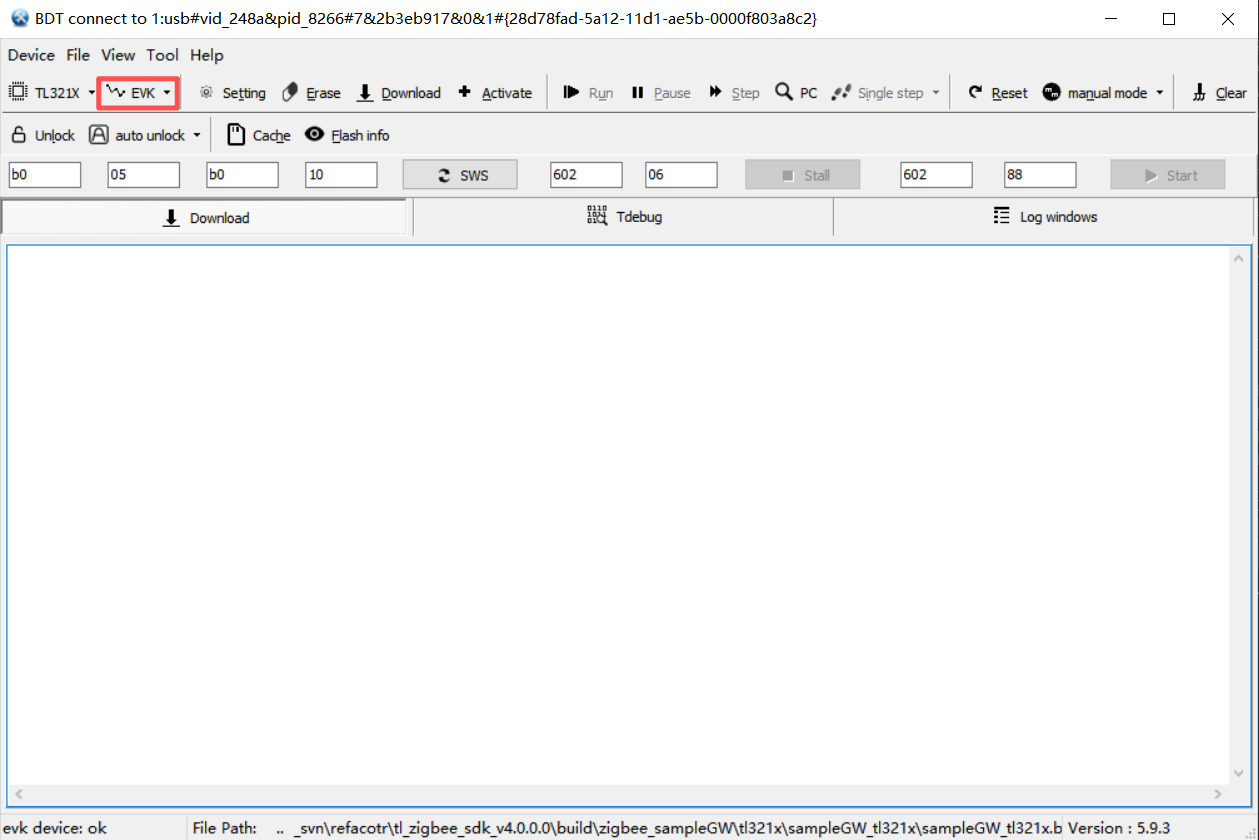
b. Select the download mode as EVK.
c. Click Setting button to open the configuration window and switch to the Flash tab. Set the initial offset address for firmware in the Download Addr bar, with the default value 0x000000.
Notes
You can download the target firmware to the SRAM or OTP target area by configuring the SRAM or OTP tab
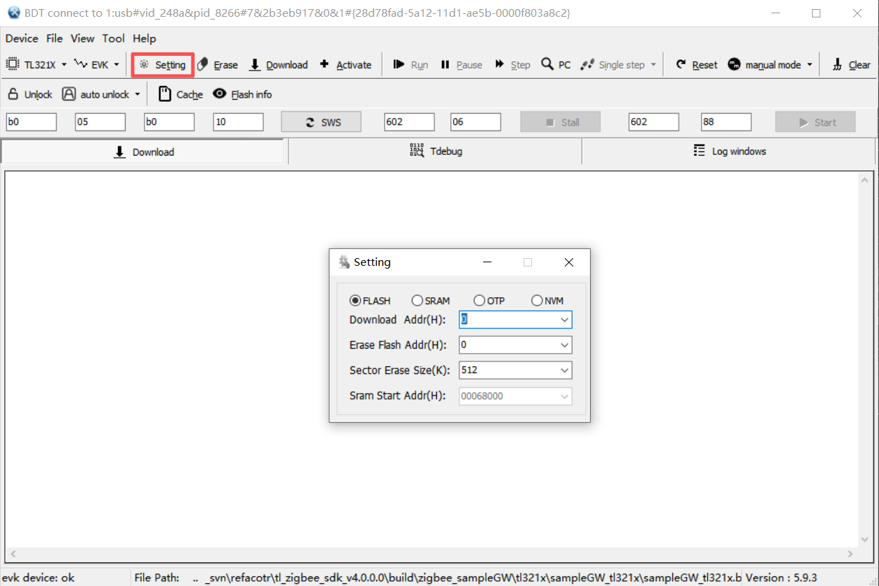
d. Click File -> Open/Reopen in the menu bar and select the
.binfirmware you compiled. After successful loading, the full file path is displayed at the bottom of the main interface.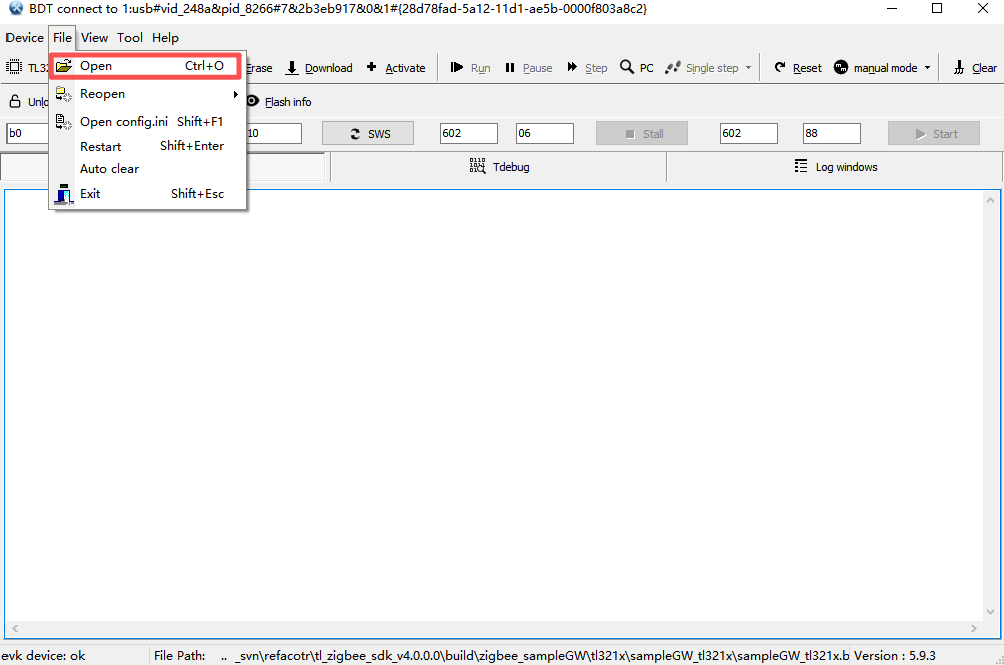
e. Check the connection status between the target board and the PC.
- If the connection status is normal, the bottom left corner of the main interface displays evk device: ok.
- If the bottom left corner of the main interface displays usb device: not found, it means the target board is not properly connected to the PC.
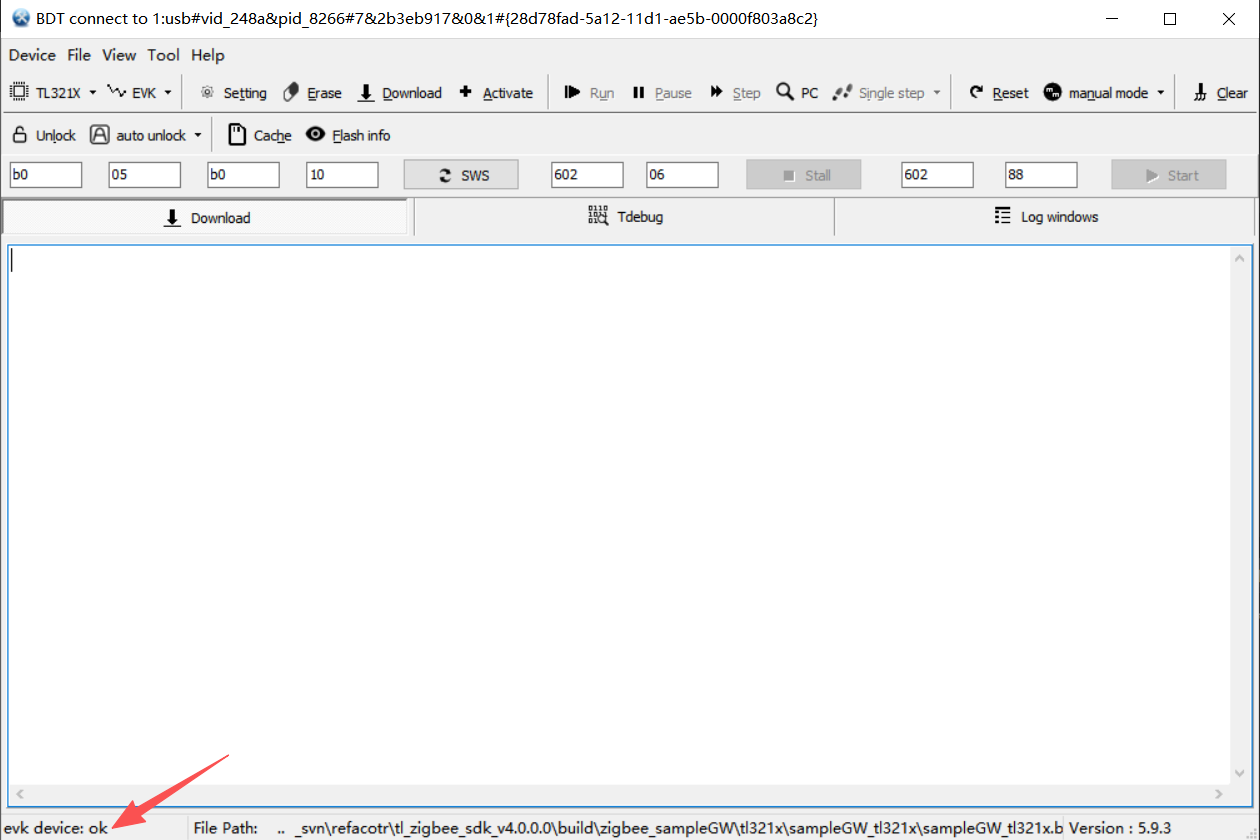
f. Click Activate, then click Unlock button or check the auto unlock option to remove Flash's write protection.
If flash is in write protection, the Download will fail, so before downloading firmware to flash, ensure flash is programmable.
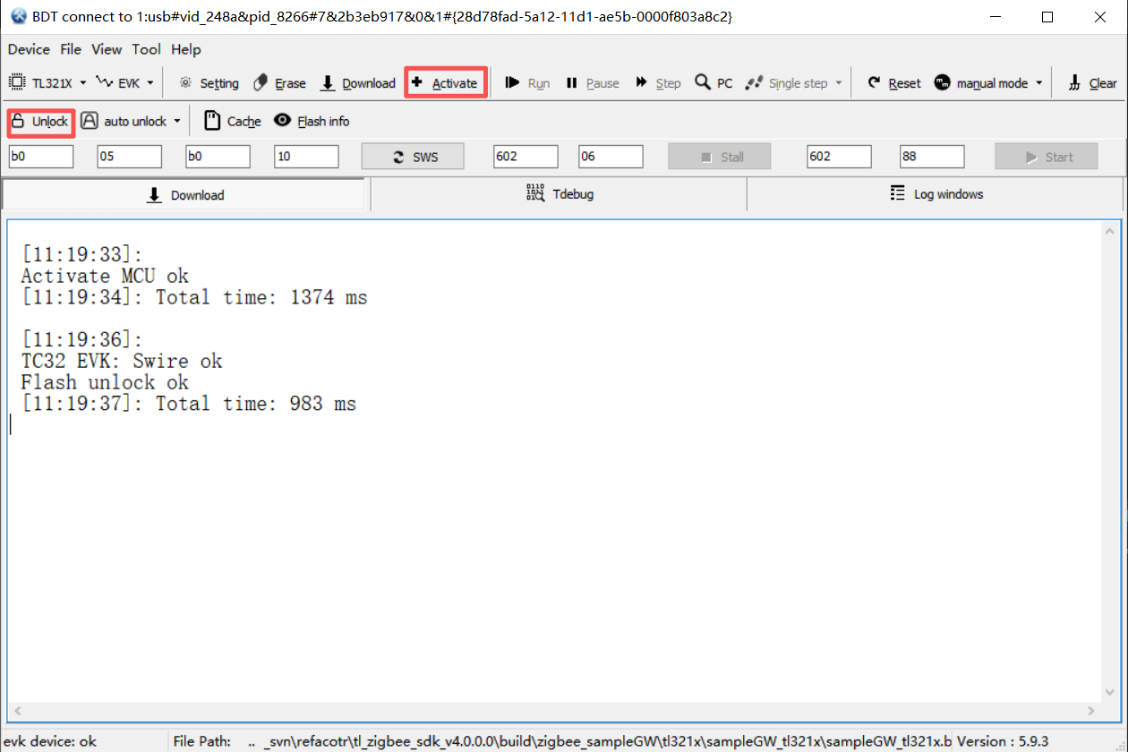
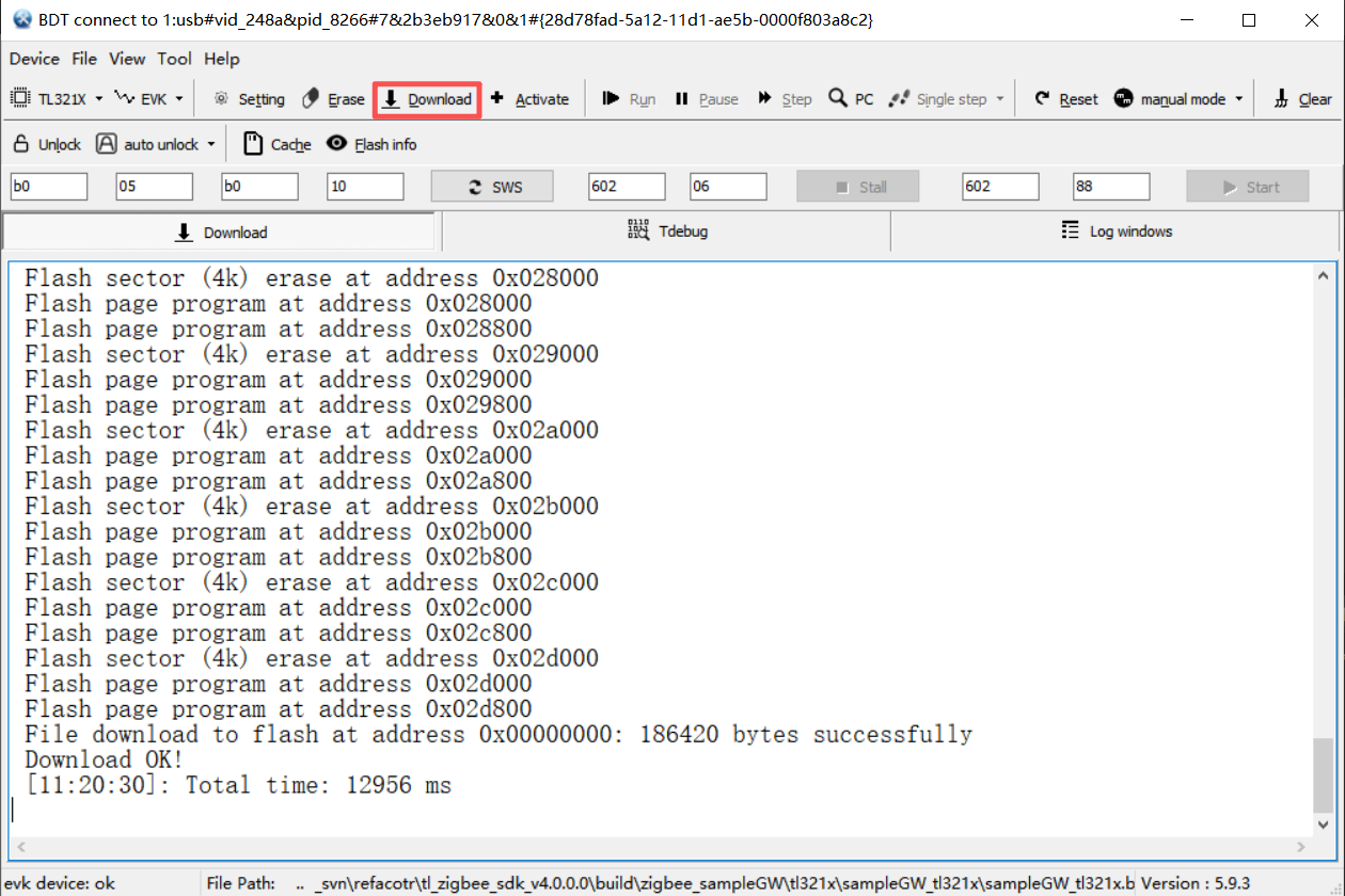
g. Click Download button and wait for the log window to prompt programming successfully.
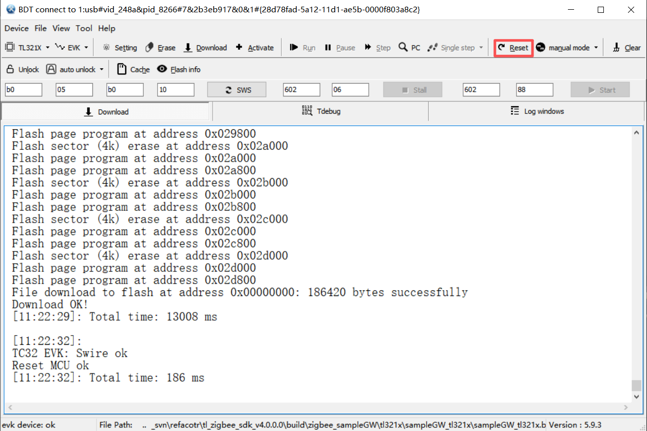
h. Set the reset mode to auto mode before flashing, or switch to manual mode after flashing and click the Reset button to manually reset the MCU.
Verify the running results
After flashing the firmware, follow the steps below to verify whether the example is running properly on the target board.
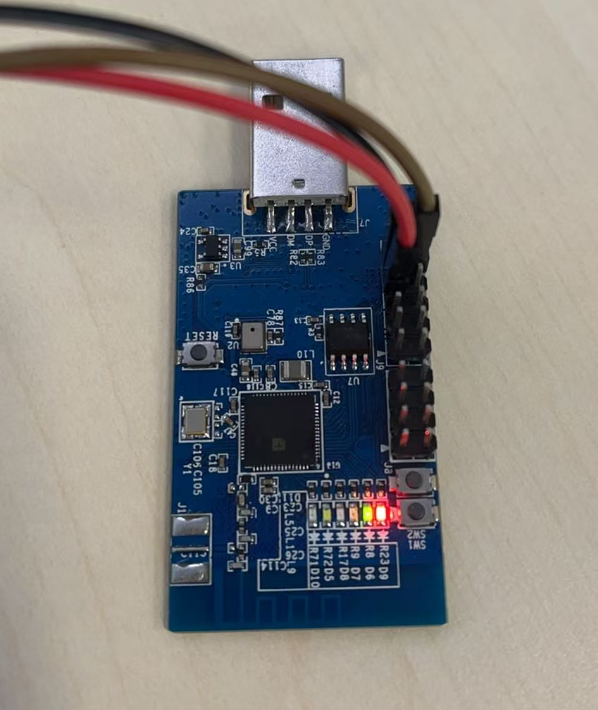
- After flashing is complete, the target board automatically resets and restarts; if it does not reset automatically, press the Reset button on the board to reset.
- Observe whether the red LED on the board lights up normally.
- Press and hold the SW1 button on the board for more than 3 seconds, and observe whether the green LED changes. LED on indicates the Zigbee network is enabled, and LED off indicates the Zigbee network is disabled.
-
If conditions permit, use professional packet capture tools such as ubiqua or wireshark to observe whether the board broadcasts Permit Join commands when the network is enabled and disabled.
References
| Document | Description |
|---|---|
| Zigbee SDK Developer Manual | Detailed software architecture, repository structure, and functional module descriptions |
Appendix 1: Frequently Asked Questions
IDE installation failed
-
Possible reason: The installation path contains Chinese characters, causing the installer to fail to recognize the path.
Solution: Modify the installation path.
-
Possible reason: Antivirus software running on the computer blocked necessary operations of the installer during installation.
Solution: Before installation, temporarily close all running antivirus or security software.
Compilation failed
-
Possible reason: The project was not cleaned after modifying header files.
Solution: Clean the project before compiling.
Flashing failed
-
Possible reason: The target board has not been activated (Activate) or unlocked (Unlock), and the chip is in a protected state, unable to receive flashing commands.
Solution: Before Download, click Activate to activate the chip. After "Activate MCU ok" appears, proceed with the Download operation to flash.
Example running abnormally
-
Possible reason: The currently flashed firmware does not match the hardware model of the board in use.
Solution: Confirm the target chip model in the project configuration, modify it to the correct configuration, then recompile, flash, and run the program.
-
Possible reason: Residual data from previously flashed programs remains in the board's flash memory.
Solution: Before flashing new firmware, perform an Erase operation to clear old data in the flash, then flash the new firmware file.