tl_bluetooth_audio_sdk Developer Handbook
Overview
With the continued growth of the audio market, Telink’s audio product portfolio has expanded to cover BT/BLE dual-mode, BT/TPSLL (Telink Proprietary Synchronous Link Layer) low-latency dual-mode mixing for headphones and TWS earbuds, as well as LE Audio applications. These solutions have been successfully deployed and mass-produced across numerous customer projects.
To meet growing market demands and support a wider range of audio chip platforms, Telink has introduced the tl_bluetooth_audio_sdk (hereinafter referred to as the SDK). The SDK provides a unified and efficient audio development framework that streamlines development across different application scenarios and reduces the complexity of audio product development.
This document covers the SDK architecture and implementation, quick start guide, application module implementation, audio paths and algorithms, Bluetooth protocol stack applications, and project implementations for different application scenarios.
SDK Key Features:
- Supports two concurrent connections in BT-only mode
- Supports four Master connections and four Slave connections (eight connections in total) in LE-only mode
- Supports one BT audio link and three LE ACL connections in BT/BLE mode
- Supports one LE Audio link and two BT ACL connections in BT/BLE mode
- Supports BT A2DP In and BIS Out
- Supports BT/BLE headset applications with simultaneous connections to a BT mobile phone and an LE Audio mobile phone, with dynamic selection of one audio stream for playback
- Supports BT/TPSLL headset applications with simultaneous connections to one TPSLL dongle and one BT mobile phone for music and call audio mixing
- Supports BT/TPSLL TWS applications with dual-mode online audio mixing
- Supports TPSLL dongles with USB audio sources for connection to BT/TPSLL TWS and headset devices
- Supports BT/BLE Audio Source dongles with USB audio and Line-In audio sources for music playback and voice communication with BT/BLE headsets
- Supports FreeRTOS, file system, Bootloader, OTA, and other system features
- Supports SBC, mSBC, AAC (decode only), CVSD, LC3/LC3P, and OPUS audio codecs
- Supports NN, ANC, VAD, ASRC, ENC, AGC, BF, and other audio algorithms
SDK Architecture
Directory Structure
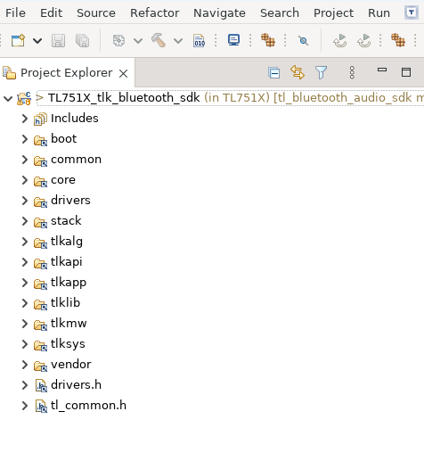
- boot: Provides build and linking configurations for SDK projects.
- common: Provides common cross-platform utility functions, such as memory management and string processing functions.
- core: Provides chip platform configuration, module log management, SDK version information, and other core system functions.
- drivers: Provides MCU-related hardware configuration and peripheral drivers, such as clock, flash, I2C, USB, GPIO, UART, and others.
- stack: Provides protocol stack header files. The corresponding source files are compiled into libraries and are not exposed to users.
- tlkalg: Provides cryptographic and audio algorithm functions.
- tlkapi: Provides common APIs, such as flash data storage and FIFO operation interfaces.
- tlkapp: Provides application-level interfaces, such as audio task scheduling and control, remote audio profile state update handling, and key/LED configuration.
- tlklib: Contains library files required for SDK operation, as well as source code from selected open-source components.
- tlkmw: Provides the middleware layer for module integration and management, offering simplified APIs for features such as Bluetooth connection management, device inquiry and reconnection, and audio playback control.
- tlksys: Provides system-related functions and components, including system tasks, timers, power management, dual-core communication, peripheral management, and HAL drivers for different chip platforms.
- vendor: Contains application-specific code for different projects.
Software Architecture
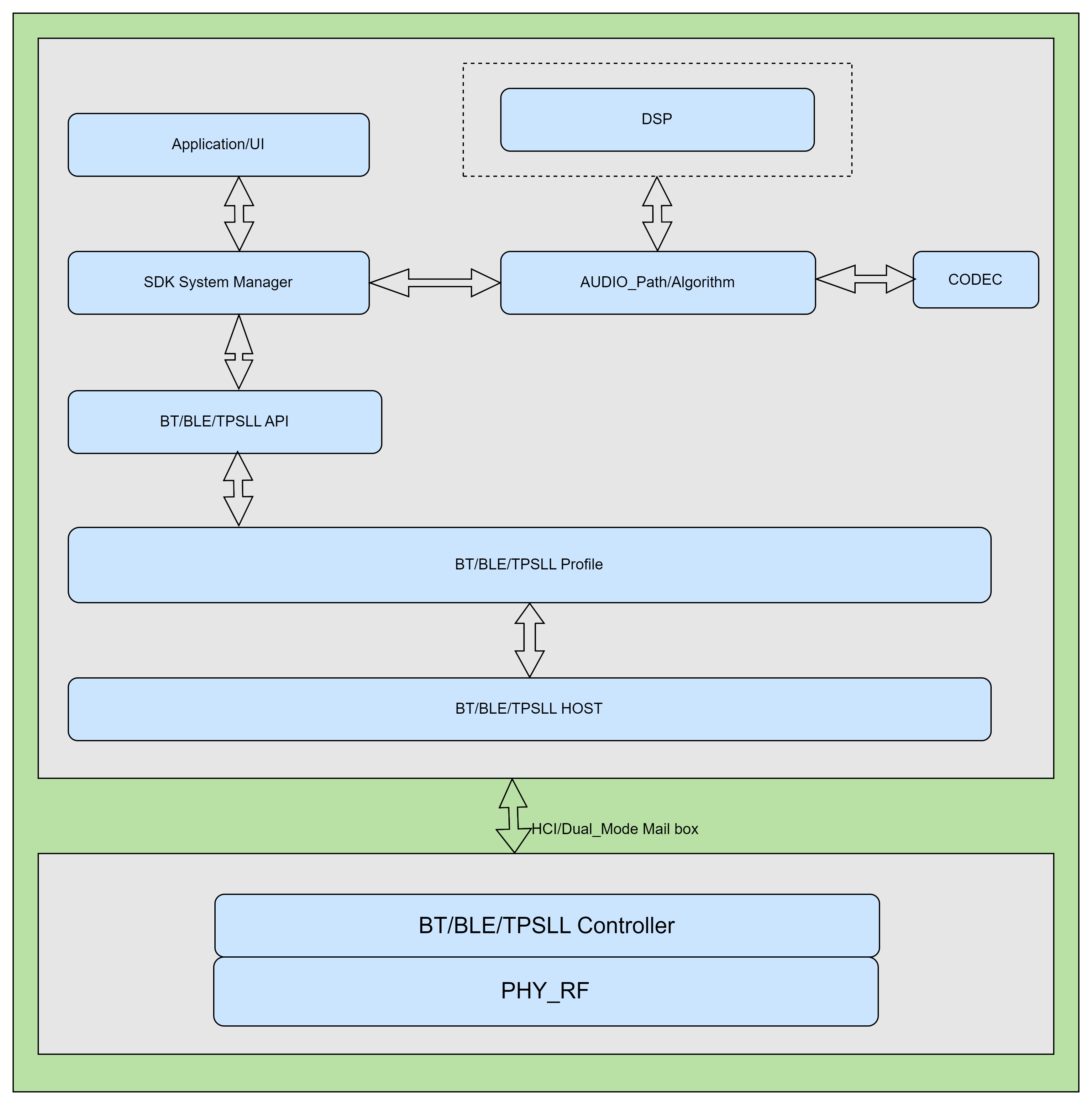
- PHY_RF: The physical layer of the IC used for RF transmission and reception
- BT/BLE/TPSLL Controller: Low-level link and logic implementation for BT/BLE/TPSLL-related controllers
- BT/BLE/TPSLL HOST: Host-layer logic implementation for the BT/BLE/TPSLL stack
- BT/BLE/TPSLL Profile: Profile implementation for the stack
- BT/BLE/TPSLL API: Middle layer between upper-level applications and the stack
- SDK System Manager: SDK management layer, including system applications, audio control, and UI integration
- Application/UI: Applications related to the SDK and specific projects, as well as customized UI configurations
- AUDIO_Path/Algorithm: Audio processing, including codec processing and additional algorithm processing.
- DSP: For multi-core chips, the DSP module is responsible for implementing complex algorithms.
- CODEC: Codec module responsible for audio playback and microphone data acquisition.
Get Started
For details about getting started with the tl_bluetooth_audio_sdk, please refer to the tl_bluetooth_audio_sdk Get Started.
SDK System Modules
Basic Initialization
Development Board Configuration
The SDK supports multiple development board configurations. Users can select the appropriate board configuration according to the development board being used.
Configuration Location: In the project's app_config.h file, select the target development board by setting the TLKHW_TYPE macro. For example:
#define TLKHW_TYPE TLKHW_TLSR9528A_EVK_C1T266A20
Add a New Board:
When a new development board needs to be supported, configure it by following the steps below.
Step 1: Add a board macro definition in board_config.h
Navigate to the vendor/common/boards directory and edit the board_config.h file to add a macro definition for the new board. The macro name follows the format TLKHW_<CHIP_MODEL>_<BOARD_MODEL>, and its value is a unique hexadecimal identifier.
Example (adding the C1T266A20 board):
#ifndef TLKHW_TLSR9528A_EVK_C1T266A20
    #define TLKHW_TLSR9528A_EVK_C1T266A20 0x266A20
#endif
Step 2: Create a board configuration file
In the vendor/common/boards directory, copy an existing board configuration file for the same or a similar target chip (for example, B92_C1T266A20.h) and rename it to the new board configuration file. The recommended naming format is <CHIP_MODEL>_<BOARD_MODEL>.h.
Info
- B92 refers to the TLSR952x and TLSR922x series chips.
Step 3: Configure the board peripherals
Edit the newly created board configuration file and configure the following peripherals according to the actual hardware connections:
- Key configuration: Define the GPIO pins for the keys (
KEYx_GPIO_IN,KEYx_GPIO_OUT) - LED configuration: Define the GPIO pins and PWM channels for the LEDs (
GPIO_LED_xxx,GPIO_LED_xxx_PWM_ID) - UART configuration: Define the TX/RX pins and DMA channels for UART (
TLKDEV_SERIALx_TX_PIN,TLKDEV_SERIALx_RX_PIN) - Codec configuration: Define the audio codec-related pins and DMA channels
- USB configuration: Define the USB DP/DM pins (if supported)
- Other peripherals: Configure GPIOs for other peripherals as required
An example configuration file structure is shown below:
#if (TLKHW_TYPE == TLKHW_TLSR9528A_EVK_C1T266A20)
    // Key Configuration
    #if (TLK_DEV_KEY_ENABLE)
        #define KEY1_GPIO_IN        GPIO_PD6
        #define KEY1_GPIO_OUT       GPIO_PD2
        // ... Other Key Configuration
    #endif

    // LED Configuration
    #if TLK_DEV_LED_ENABLE
        #define GPIO_LED_BLUE       GPIO_PD0
        // ... Other LED Configuration
    #endif

    // ... Other Peripheral Configuration
#endif
Step 4: Include the board configuration file in default_config.h
Navigate to the vendor/common directory and edit the default_config.h file. Include the new board configuration file in the corresponding chip-type conditional compilation block.
Example (adding under the B92 chip branch):
/*B92*/
#if (TLKHW_TYPE == TLKHW_TLSR9528A_EVK_C1T266A20)
    #include "vendor/common/boards/B92_C1T266A20.h"
#elif (TLKHW_TYPE == TLKHW_YOUR_NEW_BOARD)
    #include "vendor/common/boards/YOUR_NEW_BOARD.h"
// ... Other board configurations
#endif
Step 5: Select the new board in the project
In the project’s app_config.h file, set the TLKHW_TYPE macro to the macro definition of the newly added board:
#define TLKHW_TYPE TLKHW_YOUR_NEW_BOARD
Once the above steps are completed, the new board configuration takes effect.
Important Notes:
- The value of the board macro definition (hexadecimal identifier) must be unique and must not duplicate any existing board definitions.
- The board configuration file name is recommended to follow a clear naming convention to facilitate maintenance.
- When configuring peripherals, refer to the chip datasheet to verify GPIO pin functions and multiplexing relationships.
- If the new board has significant hardware differences from existing ones, it is recommended to use configuration files of other boards with the same chip as a reference template.
System Initialization
System initialization is an essential step in the SDK startup process and is performed by calling tlksys_init() within the main() function. The initialization sequence is executed in the following order:
(1) Platform Initialization (tlksys_hal_platform_init): Configures fundamental platform settings, including power supply, system clock frequency, and flash memory.
(2) Port Initialization (tlksys_port_init): Initializes the GPIO ports.
(3) Operating System Initialization (tlkos_init): Initializes the operating system abstraction layer.
(4) Dual-Core Initialization (tlksys_dualcore_init): Initializes inter-core communication for dual-core devices.
(5) Timer Initialization (tlksys_timer_coreInit): Initializes the system timers.
(6) Mutex Creation: Creates the mutexes required by the system.
(7) Initialization Complete Hook (tlksys_initFinishedHook): Executes user-defined hardware initialization routines.
The system initialization flow is shown below:
int main(void)
{
    tlksys_init();                    // Initialize the system
    tlksys_start(tlkapp_create_allTasks);  // Start the system tasks

    // Main Loop
    while (1) {
        tlksdk_main_loop();           // Controller Main Loop
        tlksys_handler();             // Handle the system messages
    }
    return 0;
}
Power Supply Configuration:
Power supply configuration uses the configuration structure returned by the tlksys_hal_port_getPlatformInitCfg() function. Implement this function in main.c to configure power supply parameters.
Configuration Function Example:
const tlksys_hal_platform_init_cfg_t *tlksys_hal_port_getPlatformInitCfg(void)
{
    static const tlksys_hal_platform_init_cfg_t cfg = {
        .clockLevel = TLK_CFG_AUDIO_CLOCK_LEVEL,  // System clock configuration
        .powerCfg = TLKSYS_HAL_INIT_POWER_CFG_DCDC,  // Power supply configuration
        // ... Other configurations
    };
    return &cfg;
}
Power Supply Mode Selection:
TLKSYS_HAL_INIT_POWER_CFG_DEFAULT- Default power supply mode (DCDC).TLKSYS_HAL_INIT_POWER_CFG_DCDC- DCDC mode, which provides high efficiency and is suitable for applications with high current consumption.TLKSYS_HAL_INIT_POWER_CFG_LDO- LDO mode, which provides lower output ripple and is suitable for applications requiring high power quality.
Power Supply Configuration Notes:
- DCDC mode: Use
sys_init(DCDC_1P4_LDO_2P0, ...)for initialization. This mode is recommended for applications that require high power efficiency. - LDO mode: Use
sys_init(LDO_1P4_LDO_2P0, ...)for initialization. This mode is recommended for applications that are sensitive to power supply ripple.
System Clock Configuration:
The system clock is configured through the clockLevel field in the tlksys_hal_platform_init_cfg_t structure. The system clock setting affects system performance, power consumption, and stability.
System Clock Configuration Methods:
(1) Configure using a macro definition: Define TLK_CFG_AUDIO_CLOCK_LEVEL in app_config.h.
#define TLK_CFG_AUDIO_CLOCK_LEVEL 3 // Clock Level
(2) Configure in the platform initialization function: The system clock configuration method varies depending on the chip model.
Clock Level Notes:
- The supported clock levels vary among chip models. Refer to the corresponding HAL implementation for details.
- The clock level setting affects:
- CPU operating frequency (
CCLK) - System bus frequency (
HCLK) - Peripheral clock frequency (
PCLK) - Flash access frequency (
MSPI)
- CPU operating frequency (
Example (B92 Chip):
// Low-power mode
clock_init(PLL_CLK_192M, PAD_PLL_DIV, PLL_DIV3_TO_CCLK,
           CCLK_DIV2_TO_HCLK, HCLK_DIV2_TO_PCLK, PLL_DIV4_TO_MSPI_CLK);
// Result: CCLK_64M_HCLK_32M_PCLK_16M

// Normal mode
CCLK_96M_HCLK_48M_PCLK_24M;  // CCLK=96MHz, HCLK=48MHz, PCLK=24MHz
Note
- The system clock setting must match the supply voltage. Higher clock frequencies typically require higher supply voltages.
- In low-power mode, the system clock frequency is automatically reduced to minimize power consumption.
- The flash access frequency should be configured according to the specifications of the flash device in use.
Controller Operating Mode Configuration
The Controller (Bluetooth Controller) operating mode is configured by calling controller_init() within the tlksys_initFinishedHook() function. This function is invoked after system initialization is complete and is used to initialize Bluetooth-related hardware and the protocol stack.
Initialization Sequence:
void tlksys_initFinishedHook(void)
{
#if (BLE_CONTROLLER_INITIAL_EN)
    // (1) RF module initialization
    rf_module_init();

    // (2)  MCU hardware initialization
    tlksdk_init_mcu_hardware();

    // (3) Controller initialization (operating mode configuration)
    controller_init(BLE_only, HCI_TR_SOC, NULL, NULL);

    // (4) Scheduler initialization
    tlksdk_sch_init();
#endif
}
Controller Operating Modes:
The mode parameter of the controller_init() function specifies the Controller operating mode:
BLE_only- Supports BLE (Bluetooth Low Energy) mode only.BT_only- Supports BR/EDR (Bluetooth Classic) mode only.BT_BLE- Supports both BLE and BR/EDR modes.BT_TPH- Supports both TPH (TPSLL proprietary protocol controller) and BR/EDR modes.BT_TPT- Supports both TPT and BR/EDR modes.BT_BLE_TPH- Supports TPH, BR/EDR, and BLE modes simultaneously.
HCI Transport Modes:
The tr_mode parameter of the controller_init() function specifies the HCI transport mode:
HCI_TR_SOC: SoC mode, where the Host and Controller reside on the same chip and communicate through an internal interface.HCI_TR_H4: H4 mode, which uses UART for HCI communication (requires an external Bluetooth chip).
Configuration Example:
// BLE mode, internal SoC communication
controller_init(BLE_only, HCI_TR_SOC, NULL, NULL);

// BT + BLE mode with internal SoC communication
controller_init(BT_BLE, HCI_TR_SOC, NULL, NULL);

// BLE mode with UART communication to an external Bluetooth chip
HCI_TR_UART hci_tr_uart = {
    .tx_pin = GPIO_PC1,
    .rx_pin = GPIO_PC2,
    .baudrate = 115200,
};
controller_init(BLE_only, HCI_TR_H4, &hci_tr_uart, NULL);
Note
- Controller initialization must be performed after RF module initialization and MCU hardware initialization.
- Different operating modes affect system power consumption and feature availability.
- When using H4 mode, ensure that the UART parameters (such as baud rate and pin configuration) are configured correctly.
- Some chip models may not support all operating modes.
Key
Key Introduction
The SDK provides a complete implementation of the Key module in the tlkmw/sys_dev/key directory. After system power-up, the key module initializes the keys through three stages: load, validate, and restore/save. It first instantiates key objects and then loads the saved configuration from flash. If the configuration is invalid, the default configuration is applied immediately and saved to flash, ensuring that a valid and consistent key configuration is available on every startup.
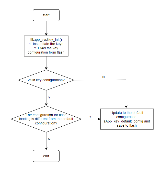
A key entity is registered with the system through the tlkkvdrv_key_insert interface. The function prototype is as follows:
/**
 * @brief           Insert a key, initialize its GPIO and start the timer.
 * @param[in]   keyID    - The key identifier, refer to 'TLKDRV_KEY_DID_ENUM'.
 * @param[in]   evtMsk   - A marker for key events, refer to 'TLKDRV_KEY_EVTMSK_ENUM'.
 * @param[in]   inPort   - Input port configuration.
 * @param[in]   outPort  - Output port configuration.
 * @param[in]   level    - Key effective level.
 * @return      TLK_ENONE is success, other value is failure.
                      -TLK_EPARAM  Invalid parameter.
                      -TLK_EREPEAT Key already exists.
                      -TLK_EQUOTA  No more key slots available.
 * @note        Initializes GPIO settings for both simple and matrix keys.
 */
int tlkdrv_key_insert(uint8_t keyID, uint8_t evtMsk, uint16_t inPort, uint16_t outPort, uint8_t level);
typedef enum
{
    TLKDRV_KEY_DID_NONE = 0x0000,
    TLKDRV_KEY_DID_KEY1 = 0x0001,
    TLKDRV_KEY_DID_KEY2 = 0x0002,
    TLKDRV_KEY_DID_KEY3 = 0x0003,
    TLKDRV_KEY_DID_KEY4 = 0x0004,
} TLKDRV_KEY_DID_ENUM;
TLKDRV_KEY_DID_ENUM is used to uniquely identify a key entity. The SDK reserves 4 IDs by default. If the number of actual keys exceeds 4, additional IDs can be added sequentially in TLKDRV_KEY_DID_ENUM.
typedef enum
{
    TLKDRV_KEY_EVTID_LONG,
    TLKDRV_KEY_EVTID_LONG_LONG,
    TLKDRV_KEY_EVTID_CLICK,
    TLKDRV_KEY_EVTID_DCLICK,
    TLKDRV_KEY_EVTID_TCLICK,
    TLKDRV_KEY_EVTID_4CLICK,
    TLKDRV_KEY_EVTID_MAX
} TLKDRV_KEY_EVTID_ENUM;
TLKDRV_KEY_EVTID_ENUM is used to define all supported key event types, including but not limited to single click, double click, triple click, and long press.
typedef enum
{
    TLKDRV_KEY_EVTMSK_NONE      = 0x00,
    TLKDRV_KEY_EVTMSK_LONG      = (1 << TLKDRV_KEY_EVTID_LONG),
    TLKDRV_KEY_EVTMSK_LONG_LONG = (1 << TLKDRV_KEY_EVTID_LONG_LONG),
    TLKDRV_KEY_EVTMSK_CLICK     = (1 << TLKDRV_KEY_EVTID_CLICK),
    TLKDRV_KEY_EVTMSK_DCLICK    = (1 << TLKDRV_KEY_EVTID_DCLICK),
    TLKDRV_KEY_EVTMSK_TCLICK    = (1 << TLKDRV_KEY_EVTID_TCLICK),
    TLKDRV_KEY_EVTMSK_4CLICK    = (1 << TLKDRV_KEY_EVTID_4CLICK),

    TLKDRV_KEY_EVTMSK_DEFAULT = TLKDRV_KEY_EVTMSK_CLICK | TLKDRV_KEY_EVTMSK_DCLICK | TLKDRV_KEY_EVTMSK_TCLICK | TLKDRV_KEY_EVTMSK_4CLICK |
                                TLKDRV_KEY_EVTMSK_LONG | TLKDRV_KEY_EVTMSK_LONG_LONG,


} TLKDRV_KEY_EVTMSK_ENUM;
TLKDRV_KEY_EVTMSK_ENUM describes the set of configurable key behaviors. The default value is TLKDRV_KEY_EVTMSK_DEFAULT. Once this configuration is selected, the key supports all behaviors defined in it.
typedef enum
{
    KEY_EVT_MODE_NONE = 0x00,

    KEY_EVT_MODE_ENABLE_PAIRING_MODE,
    KEY_EVT_MODE_CALL_ACCEPT,
    KEY_EVT_MODE_CALL_HUNG_UP,
    KEY_EVT_MODE_VOLUME_DOWN,
    KEY_EVT_MODE_VOLUME_UP,
    KEY_EVT_MODE_MUSIC_FORWARD,
    KEY_EVT_MODE_MUSIC_BACKWARD,
        ...
    KEY_EVT_MODE_BTTPSLL_MIC_SWITCH,            // debug for tpsll dongle
    KEY_EVT_MODE_SYSTEM_POWEROFF_REQ,
    KEY_EVT_VENDOR_CONFIG,
    KEY_EVT_VENDOR_CONFIG_1   = KEY_EVT_VENDOR_CONFIG,
        ...
    KEY_EVT_VENDOR_CONFIG_END = KEY_EVT_VENDOR_CONFIG_12,

    KEY_EVT_MODE_MAX
} tlkdrv_key_evt_mode_e;
tlkdrv_key_evt_mode_e defines the specific events to be reported after a key behavior is triggered. For example, a "KEY1 single click" event can be mapped to "increase music volume".
typedef struct
{
    uint8_t  keyID;
    uint8_t  level;
    uint8_t  isrChn;
    uint8_t  state;
    uint8_t  clickCnt;
    uint8_t  evtMsk;
    uint16_t timeMs;
    uint16_t inPort;
    uint16_t outPort;
} tlkdrv_key_unit_t;
tlkdrv_key_unit_t fully describes the static and dynamic attributes of a key entity, including active level, interrupt channel, real-time state, single-click counter, event mask, timer, and input/output detection pins.
typedef struct {
    uint8_t            isNeedScanTimer;
    uint8_t            resv3byte[3];
    uint32_t           lastScanTick;
    TlkOsTimerHandle_t scanTimer;
    tlkdrv_key_unit_t  unit[TLKDRV_KEY_MAX_NUMB];
} tlkdrv_key_ctrl_t;
tlkdrv_key_ctrl_t is the global control block of the key module, responsible for managing scan strategy, tick tracking, timer resources, and runtime data of all key entities.
Key Usage
When a key is triggered, the driver layer captures the event and parses it into keyID and evtID. The state machine then validates the event and dispatches commands to the corresponding task according to the message mapping table, forming a closed-loop key response mechanism.
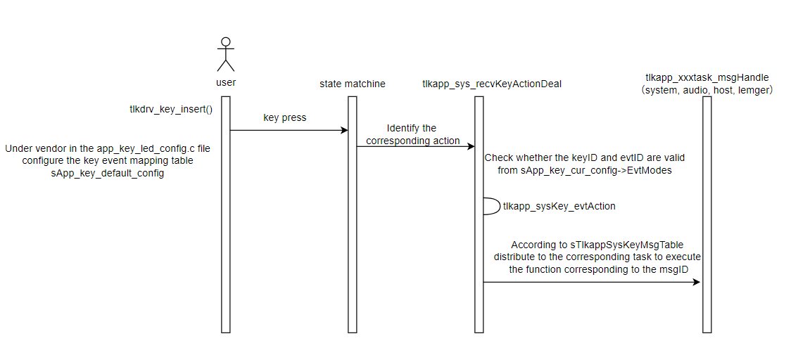
API Overview
typedef void (*tlkdrv_vendor_config_cb_t)(void);
tlkdrv_key_evt_mode_e is a callback function used to handle custom events (KEY_EVT_VENDOR_CONFIG) in addition to standard events. Users can implement application logic in this function. It does not rely on the SDK message dispatch mechanism to route events to specific tasks.
/**
 * @brief       Register a vendor configuration callback function.
 * @param[in]   eventMode  - Event mode identifier (KEY_EVT_VENDOR_CONFIG_x).
 * @param[in]   cb         - Callback function to register.
 * @return      none.
 * @note        Only registers callback if eventMode is within valid range.
 */
void tlkdrv_key_registerVendorConfigCallback(uint8_t eventMode, tlkdrv_vendor_config_cb_t cb);
The event handler corresponding to the custom event KEY_EVT_VENDOR_CONFIG_X is called by other tlkdrv_key_registerVendorConfigXCallback functions.
/**
 * @brief       Register a vendor configuration callback for event mode KEY_EVT_VENDOR_CONFIG_1.
 * @param[in]   cb  - Callback function to register.
 * @return      none.
 * @note        Wrapper for tlkdrv_key_registerVendorConfigCallback with fixed event mode.
 */
void tlkdrv_key_registerVendorConfig1Callback(tlkdrv_vendor_config_cb_t cb)
{
    tlkdrv_key_registerVendorConfigCallback(KEY_EVT_VENDOR_CONFIG_1, cb);
}
This function is used to register the callback for the KEY_EVT_VENDOR_CONFIG_X event.
LED
LED Module Introduction
The LED module in the SDK is used for status indication, providing a visual representation of the device’s current state. The LED interface provides a unified API, making it easy to use directly. It supports two types of interfaces, GPIO (IO) and PWM, to implement LED on/off, blinking, and breathing effects, meeting various application scenarios.
LED Usage Flow
LED Initialization:
LED initialization is performed within the system initialization function. When RTOS is enabled, the LED thread runs under the system thread. To use the LED module, the corresponding enable macro must be defined:
#define TLK_DEV_LED_ENABLE 1
The initialization interface is shown below:
void tlkapp_sysLed_init(void);
LED Configuration:
The GPIO and PWM configurations of the LED can be set via macro definitions. The specific configuration macros are as follows:
#define GPIO_LED_BLUE        GPIO_PB3
#define GPIO_LED_BLUE_PWM_ID PWM0_ID
#define GPIO_LED_RED         GPIO_PB4
#define GPIO_LED_RED_PWM_ID  PWM1_ID
#define GPIO_LED_NUMS        2
#define LED_ON_LEVEL         1
The above configurations are located in the hardware-specific *.h files under the vendor/common/board directory of the SDK.
If the value of GPIO_LED_XXXX_PWM_ID is a valid PWMx_ID, the LED driver mode defaults to PWM. Otherwise, GPIO mode is used.
LED blinking behavior varies under different states, and different patterns can be selected as needed. The default configuration table is stored in the tlkdrv_led_patterns array.
typedef struct
{
    uint16_t behavior;
    uint16_t stepUs;
    uint16_t dutyFlushMs;
    uint16_t onTimerMs;
    uint16_t offTimerMs;
    uint16_t flashCounts;
}tlkdrv_led_pattern_t;
- behavior: Indicates the LED state
- 0: always off
- 1: always on
- 2: blinking
- 3: breathing
- stepUs: PWM step size in microseconds (us)
- dutyFlushMs: PWM update interval in milliseconds (ms)
- onTimerMs: LED on duration in milliseconds (ms)
- offTimerMs: LED off duration in milliseconds (ms)
- flashCounts: Number of LED blinks
tlkdrv_led_pattern_t is the LED configuration structure, containing LED state, PWM step size, timing interval, on/off duration, and blink count. The SDK provides a default configuration table. Users can add new configurations as needed and add them to the tlkdrv_led_patterns array.
static const tlkdrv_led_pattern_t tlkdrv_led_patterns[TLKDRV_LED_PATTERN_MAX_STATE] = {
    [TLKDRV_LED_PATTERN_OFF]                 = {.behavior = 0, .stepUs = 0,   .dutyFlushMs = 0,   .onTimerMs = 0,    .offTimerMs = 0,    .flashCounts = 0xFFFFU},
    [TLKDRV_LED_PATTERN_ON]                  = {.behavior = 1, .stepUs = 0,   .dutyFlushMs = 0,   .onTimerMs = 0,    .offTimerMs = 0,    .flashCounts = 0xFFFFU},
    [TLKDRV_LED_PATTERN_FLASH_SLOW]          = {.behavior = 2, .stepUs = 0,   .dutyFlushMs = 0,   .onTimerMs = 2000, .offTimerMs = 2000, .flashCounts = 0xFFFFU},
    [TLKDRV_LED_PATTERN_FLASH_FAST]          = {.behavior = 2, .stepUs = 0,   .dutyFlushMs = 0,   .onTimerMs = 200,  .offTimerMs = 200,  .flashCounts = 0xFFFFU},
    [TLKDRV_LED_PATTERN_FLASH_PAIR]          = {.behavior = 2, .stepUs = 0,   .dutyFlushMs = 0,   .onTimerMs = 500,  .offTimerMs = 1500, .flashCounts = 0xFFFFU},
    [TLKDRV_LED_PATTERN_IDLE]                = {.behavior = 2, .stepUs = 0,   .dutyFlushMs = 0,   .onTimerMs = 200,  .offTimerMs = 800,  .flashCounts = 0xFFFFU},

    [TLKDRV_LED_PATTERN_BREATH_SLOW]         = {.behavior = 3, .stepUs = 25,  .dutyFlushMs = 10,  .onTimerMs = 2000, .offTimerMs = 2000, .flashCounts = 0xFFFFU},
    [TLKDRV_LED_PATTERN_BREATH_FAST]         = {.behavior = 3, .stepUs = 125, .dutyFlushMs = 5,   .onTimerMs = 200,  .offTimerMs = 200,  .flashCounts = 0xFFFFU},
    [TLKDRV_LED_PATTERN_BREATH_PAIR]         = {.behavior = 3, .stepUs = 50,  .dutyFlushMs = 5,   .onTimerMs = 500,  .offTimerMs = 500,  .flashCounts = 0xFFFFU},

};
In actual use, users can configure settings within the tlkapp_sysLed_stateToPatternHook function, which is a virtual function that users can define as needed. If the user does not define it, the SDK uses the default configuration. The default SDK configuration is shown below:
__attribute__((weak)) tlkdrv_led_pattern_e tlkapp_sysLed_stateToPatternHook(TLKAPP_LED_STATE state)
{
    static const tlkdrv_led_pattern_e sTlkapp_sysLed_defaultCfg[TLKAPP_LED_STATE_NUM] = {
        [TLKAPP_LED_STATE_POWERON]      = TLKDRV_LED_PATTERN_ON_1S,
        [TLKAPP_LED_STATE_POWEROFF]     = TLKDRV_LED_PATTERN_ON_1S,
        [TLKAPP_LED_STATE_POWERON_IDLE] = TLKDRV_LED_PATTERN_IDLE,
        [TLKAPP_LED_STATE_PARING]       = TLKDRV_LED_PATTERN_FLASH_FAST,
        [TLKAPP_LED_STATE_CONNECTED]    = TLKDRV_LED_PATTERN_BREATH_SLOW,
        [TLKAPP_LED_STATE_LOWBATTARY]   = TLKDRV_LED_PATTERN_SLOW_FLASH_3_TIMES,
    };
    return sTlkapp_sysLed_defaultCfg[state];
}
LED Control
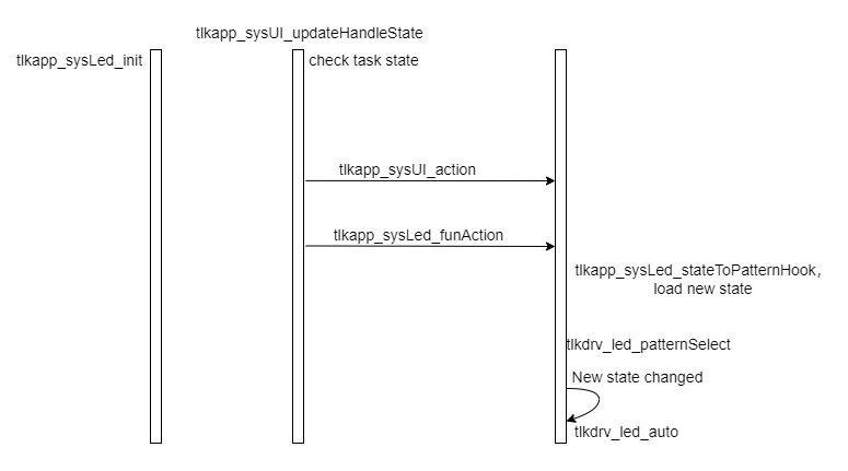
LED control in the SDK is event-driven. The unified interface is tlkapp_sysUI_updateHandleState, which updates the LED state by invoking the corresponding LED module APIs according to the current system state.
int tlkapp_sysUI_updateHandleState(uint08 group, uint16 handle, uint08 state)
{
    tlksys_mutex_lock(TLKSYS_MUTEX_UI);
    int res = tlkapp_sysUI_updateHandleStateCore(group, handle, state);
    tlksys_mutex_unlock(TLKSYS_MUTEX_UI);
    return res;
}
- group: Group ID indicating which group the event belongs to. The available options are as follows:
typedef enum
{
    TLKAPP_UI_HANDLE_GROUP_SYS,
    TLKAPP_UI_HANDLE_GROUP_BT,
    TLKAPP_UI_HANDLE_GROUP_BLE,
    TLKAPP_UI_HANDLE_GROUP_TPSLL,
    TLKAPP_UI_HANDLE_GROUP_MAX,
} TLKAPP_UI_HANDLE_GROUP_ENUM;
- handle: Handle ID indicating which channel triggered the event.
- state: State indicating which LED effect should be applied.
Finally, the following interface is called to perform LED state switching:
int tlkapp_sysLed_funAction(TLKAPP_LED_STATE led_fun);
typedef enum
{
    TLKAPP_LED_STATE_POWERON,
    TLKAPP_LED_STATE_POWEROFF,
    TLKAPP_LED_STATE_POWERON_IDLE,
    TLKAPP_LED_STATE_PARING,
    TLKAPP_LED_STATE_CONNECTED,
    TLKAPP_LED_STATE_LOWBATTARY,
    TLKAPP_LED_STATE_NUM,
} TLKAPP_LED_STATE;
TLKAPP_LED_STATE indicates the current system state.
The usage flow is as follows:
UART
UART Module Configuration
UART Module Initialization:
Before using the UART module, it must be initialized by calling the following function:
int tlkdrv_serial_mount(uint8_t port, uint32_t baudRate, uint16_t txPin, uint16_t rxPin, uint8_t txDma, uint8_t rxDma);
- port: UART port number, corresponding to UART0–UART1
- baudRate: UART baud rate
- txPin: UART TX pin
- rxPin: UART RX pin
- txDma: UART TX DMA channel. If DMA mode is used for UART transmission, configure this parameter with the TX DMA channel number. Set it to
0when DMA transmission is not used. - rxDma: UART RX DMA channel
Data Buffer Configuration:
The SDK UART module provides configurable data buffers. Users can adjust the buffer settings according to their requirements. The default configuration is as follows.
#define TLKMDI_COMM_SERIAL_RBUFF_NUMB 2
#define TLKMDI_COMM_SERIAL_RBUFF_SIZE 540
#define TLKMDI_COMM_SERIAL_SBUFF_NUMB 4
#define TLKMDI_COMM_SERIAL_SBUFF_SIZE 128
- TLKMDI_COMM_SERIAL_RBUFF_NUMB: Number of RX buffers
- TLKMDI_COMM_SERIAL_RBUFF_SIZE: Size of each RX buffer
- TLKMDI_COMM_SERIAL_SBUFF_NUMB: Number of TX buffers
- TLKMDI_COMM_SERIAL_SBUFF_SIZE: Size of each TX buffer
Transmit Buffer Configuration:
int tlkdrv_serial_setTxQFifo(uint8_t port, uint16_t fnumb, uint16_t fsize, uint8_t *pBuffer, uint32_t buffLen);
- port: UART port number, corresponding to UART0–UART1
- fnumb: Number of RX buffers
- fsize: Size of each RX buffer
- pBuffer: Start address of the TX buffer
- buffLen: Length of the TX buffer
Receive Buffer Configuration:
int tlkdrv_serial_setRxQFifo(uint8_t port, uint16_t fnumb, uint16_t fsize, uint8_t *pBuffer, uint32_t buffLen);
- port: UART port number, corresponding to UART0–UART1
- fnumb: Number of RX buffers
- fsize: Size of each RX buffer
- pBuffer: Start address of the RX buffer
- buffLen: Length of the RX buffer
UART Module Enablement:
Before using the UART module, it must be enabled by calling the following function during system initialization:
int tlkdrv_serial_open(uint8_t port);
- port: UART port number, corresponding to UART0–UART1
UART Transmission Interface:
The tlkdrv_serial_write interface allows users to transmit data through the specified UART port.
int tlkdrv_serial_send(uint8_t port, uint8_t *pData, uint16_t dataLen);
- port: UART port number, corresponding to UART0–UART1
- pData: Pointer to the data to be transmitted
- dataLen: Length of the data to be transmitted
UART Reception Interface:
Before receiving UART data, register the receive callback function using the following interface:
void tlkdrv_serial_regCB(uint8_t port, TlkDrvSerialRecvCB cb);
- port: UART port number, corresponding to UART0–UART1
- cb: Receive callback function. It is called when UART data is received, with the received data passed as an argument.
UART Interrupt Registration:
The SDK UART module provides interrupt registration interfaces, allowing users to register interrupt handlers as needed.
LIC_ISR_REGISTER_OS(tlk_uartx_irq_handler, IRQ_UARTx)
When using DMA mode for UART reception, register the DMA interrupt, and call tlkdrv_serial_dma_irq_handler inside the interrupt handler.
PLIC_ISR_REGISTER_OS(tlk_dma_irq_handler, IRQ_DMA)
Tone
The tone module is used to play prompt tones for events such as connection, disconnection, and device discovery. The SDK supports two prompt tone formats: ADPCM and SBC. Users can select either format as needed. The downloaded tone files must match the tone format configured in the SDK. Mixed formats are not supported.
Tone Configuration
To use the tone feature, enable the TLK_CFG_TONE_ENABLE macro in the app_config.h file of the corresponding project.
#define TLK_CFG_TONE_ENABLE 1
If the downloaded tone files use the SBC format, enable the TONE_SBC_EN macro in the app_config.h file.
#define TONE_SBC_EN 1
Tone Initialization
Tone initialization depends on the audio task. Therefore, the audio task must be initialized during system initialization.
#if (TLK_MW_AUDIO_ENABLE)
    tlksys_task_create(TLKSYS_TASKID_AUDIO, tlkapp_audio_getTaskCfg());
#endif
Tone File Storage Location
To use the tone feature, first download the generated tone files to the specified location in Flash. For details about the address, see Section Tone Download. The relevant tone configuration is as follows:
tone_cfg_t g_tone_cfg = {
                        .volume = 512,
                    #if TONE_SBC_EN
                        .type   = TONE_TYPE_SBC,
                    #else
                        .type   = TONE_TYPE_ADPCM,
                    #endif
                         .busy   = 0,
                         .ready  = 0,
                         .buff   = NULL};
Tone Playback Interface
The SDK supports two tone encoding formats, but the playback process is the same for both. To play a tone, call the tone_play interface, which plays the corresponding tone file based on the configured tone format.
In the SDK, this interface is typically not called directly. Since tone playback is asynchronous, it is triggered by events. The tlkapp_sysUI_updateHandleState() interface is used to trigger the corresponding UI events. When a tone needs to be played, tlkapp_sysUI_sendStartToneMsg() is called to notify the UI to start tone playback.
static void tlkapp_sysUI_sendStartToneMsg(uint08 tone_indx)
{
    (void)tone_indx;
    uint08 data[2] = {tone_indx,1};
    tlksys_sendMsg(TLKSYS_TASKID_AUDIO, TLKSYS_AUD_MSGID_START_TONE_CMD, data, 2);
}
The TLKSYS_AUD_MSGID_START_TONE_CMD event invokes int tlkmdi_tone_start(uint16 handle, uint32 param), which plays the corresponding tone file based on the configured tone format.
int tlkmdi_tone_start(uint16 handle, uint32 param)
USB
USB Directory Structure Overview
The Telink USB module supports the standard USB 1.1 and USB 2.0 specifications. For details about the supported protocol types, refer to the USB Core Specification.
The USB module is externally powered. The SDK currently supports the UDB, MSC, and UAC device classes. Users can enable or disable the USB module by modifying the TLK_CFG_USB_ENABLE macro, and control the availability of specific device classes by modifying the corresponding TLK_USB_XXX_ENABLE macros.
The following figure shows the file structure of the USB module:
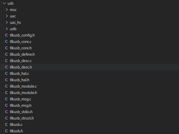
- tlkusb.*: Interfaces related to USB module enable/disable control, application mode switching, enumeration processing, and other functions.
- tlkusb_struct.h: Structure definitions related to the USB module.
- tlkusb_msg.*: Interfaces for USB module DCD message processing, currently used only by the High-Speed USB module.
- tlkusb_hal.*: Low-level HAL interfaces for the USB module. Currently, supports the USB 1.1 modules of multiple chip platforms.
- tlkusb_desc.*: Interfaces related to USB descriptors.
- tlkusb_define.h: Macro definitions related to the USB module.
- tlkusb_core.*: Core USB processing interfaces, including initialization, enumeration, and control operations.
- tlkusb_module.*: Abstract USB interfaces, including initialization, enumeration, and control operations.
- msc/uac/uac_hs/udb: Application-layer interfaces and data processing implementations for the USB module, corresponding to
TLKHAL_USB_MODE_ENUM. Currently, the SDK supports these four modes only.
USB Interface Usage
USB Module Initialization:
int tlkusb_init(uint08 index, uint16 usbID);
- index: USB module index. This parameter is applicable only to systems that support multiple USB modules.
- usbID: USB ID corresponding to the USB host application in UDB mode. This parameter is currently not used in other modes.
USB Module Open Interface:
int tlkusb_open(uint08 index, TLKHAL_USB_MODE_ENUM modType);
- index: USB module index. This parameter is applicable only to systems that support multiple USB modules.
- modType: USB device type, corresponding to
TLKHAL_USB_MODE_ENUM.
This interface enables the USB event-driven mechanism, configures the interrupts required for USB enumeration, and sets the corresponding interrupt masks. If the enumeration process is triggered in loop mode, this interface does not need to be called.
void tlkusb_hal_enable_eventMode(void);
This interface registers and attaches the USB module loop handler. In the current SDK implementation, the USB module runs under the TLKSYS_TASKID_SYSTEM task.
tlksys_task_regEvtCB(TLKSYS_TASKID_SYSTEM,TLKSYS_TASK_EVT_SYS_USB,tlkusb_handler);
USB Enumeration Process
The USB enumeration process in the SDK currently uses an interrupt-driven mechanism. Call the tlkusb_hal_enable_eventMode() interface to enable the IRQs related to the USB module and handle USB enumeration events in the IRQ handler. The following section uses the UDB device on the B92 platform as an example to illustrate the USB enumeration process with code examples.
(1) Device Initialization
tlksys_task_regEvtCB(TLKSYS_TASKID_SYSTEM,TLKSYS_TASK_EVT_SYS_USB,tlkusb_handler);
tlkusb_init(TLK_CFG_USB_UDB_INDEX, 0x120);
tlkusb_open(TLK_CFG_USB_UDB_INDEX, TLKUSB_MODTYPE_UDB);
tlkusb_hal_enable_eventMode();
(2) Interrupt Service Routine Registration and Handling
The tlkusb_ctrl_ep_irq_handler retrieves the USB IRQ mask and stores it into the global array sTlkUsbReg.ctrlEpIrq[index], where the index refers to the USB index. It then clears the corresponding USB IRQ mask.
Subsequently, the USB bit in the system module is set, triggering the corresponding registered USB loop handler.
The detailed handling of the subsequent USB enumeration flow is performed within the USB loop handler.
_attribute_ram_code_sec_ void tlk_usb_ctrl_ep_irq_handler(void)
{
    tlkusb_ctrl_ep_irq_handler(0);
}
PLIC_ISR_REGISTER_OS(tlk_usb_ctrl_ep_irq_handler, IRQ_USB_CTRL_EP_SETUP)
PLIC_ISR_REGISTER_OS(tlk_usb_ctrl_ep_irq_handler, IRQ_USB_CTRL_EP_DATA)
PLIC_ISR_REGISTER_OS(tlk_usb_ctrl_ep_irq_handler, IRQ_USB_CTRL_EP_STATUS)
PLIC_ISR_REGISTER_OS(tlk_usb_ctrl_ep_irq_handler, IRQ_USB_RESET)
PLIC_ISR_REGISTER_OS(tlk_usb_ctrl_ep_irq_handler, IRQ_USB_CTRL_EP_SETINF)
(3) USB Loop Handler
The core USB enumeration processing mainly includes handling Setup and Data stages during the enumeration process, as well as responding to descriptor requests.
void tlkusb_handler(void);
USB Device Type
(1) TLKUSB_MODTYPE_UDB
A USB Debug Class device used for debugging, typically working with a host-side application. The related descriptors are defined in tlkusb_udbDesc.c.
Endpoint Resource Usage:
Endpoint resource usage is as follows. It may vary across different chip platforms and is configurable as required.
    #define TLKUSB_UDB_EDP_DBG_IN  USB_EDP3_IN
    #define TLKUSB_UDB_EDP_DBG_OUT USB_EDP5_OUT
    #define TLKUSB_UDB_EDP_VCD_IN  USB_EDP8_IN
    #define TLKUSB_UDB_EDP_VCD_OUT USB_EDP6_OUT
Data Processing Interface:
The data processing interface reads data from the TLKUSB_UDB_EDP_DBG_OUT endpoint and parses whether it is a USB download command or a USB shell command.
static void tlkusb_udbctrl_handler(void);
USB shell command handling is not strictly defined and is configurable by customers.
void tlkusb_debug_shell_hook(uint8_t *pData, uint16_t dataLen);
(2) TLKUSB_MODTYPE_UAC
USB Audio Class device type. The related descriptors are defined in tlkusb_uacDesc.c.
Endpoint Resource Usage:
Endpoint resource usage is as follows. It may vary across different chip platforms and is configurable as required.
    #define TLKUSB_UAC_EDP_HID USB_EDP1_IN
    #define TLKUSB_UAC_EDP_MIC USB_EDP7_IN
    #define TLKUSB_UAC_EDP_SPK USB_EDP6_OUT
Data Processing Interface:
void tlkusb_uacirq_handler(void);
void tlkusb_uacspk_recvData(uint32 tick);
void tlkusb_uacmic_fillData(uint32 tick);
(3) TLKUSB_MODTYPE_MSC
USB Mass Storage Class device type. The related descriptors are defined in tlkusb_mscDesc.c.
Endpoint Resource Usage:
Endpoint resource usage is as follows. It may vary across different chip platforms and is configurable as required.
    typedef enum{
        TLKUSB_MSC_EDP_IN  = 1, //USB_EDP1_IN
        TLKUSB_MSC_EDP_OUT = 5, //USB_EDP5_OUT
    }TLKUSB_MSC_EDP_ENUM;
Data Processing Interface:
void tlkusb_mscctrl_handler(void);
Timer
This chapter describes the timer system architecture in the SDK. The timer system includes three types: system thread timers (tlksys_timer), OS abstraction layer timers (tlkos_timer), and hardware timers.
timerList Introduction and Implementation Principle
tlkapi_timerList is a low-level timer management module in the SDK. It provides functions for creating, starting, stopping, and destroying timers, as well as handling timer timeout events.
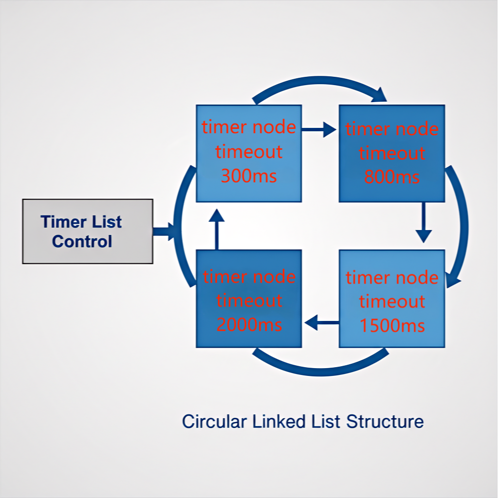
It uses a circular linked list data structure to organize timers and sorts them according to their expiration time to efficiently manage and schedule multiple timers. Both system thread timers (tlksys_timer) and OS abstraction layer timers (bare-metal implementation) are built on top of this module for unified timer management and scheduling.
Users do not need to be concerned with the internal implementation details of this module and can directly use the APIs provided by tlksys_timer and tlkos_timer.
Key Features:
- Circular linked list management: All timers are organized using a circular linked list and sorted by expiration time.
- State machine management: Timers have a complete lifecycle state management mechanism.
- Auto-reload support: Supports both one-shot and periodic trigger modes.
- Asynchronous safe scheduling: Operations during callback execution (such as stopping, restarting, or destroying) are not executed immediately but are deferred via state flags until the callback completes.
(1) Timer Node Structure
typedef struct TlkApiTimer_s {
    uint8_t               malloced;     // Whether dynamically allocated
    uint8_t               runningCB;    // Whether the callback function is currently executing
    uint8_t               autoReload;   // Auto-reload flag
    uint8_t               nowState;     // Current state
    uint32_t              arrival;      // Expiration timestamp
    uint32_t              timeout;      // Timeout duration
    void*                 userArg;      // User parameter
    TlkApiTimerCB_t       timerCB;      // Callback function
    struct TlkApiTimer_s *pNext;        // Pointer to the next node
} TlkApiTimer_t;
(2) Timer List Control Structure
typedef struct{
    TlkApiTimer_t *pList;  // Pointer to the first timer node
} TlkApiTimerList_t;
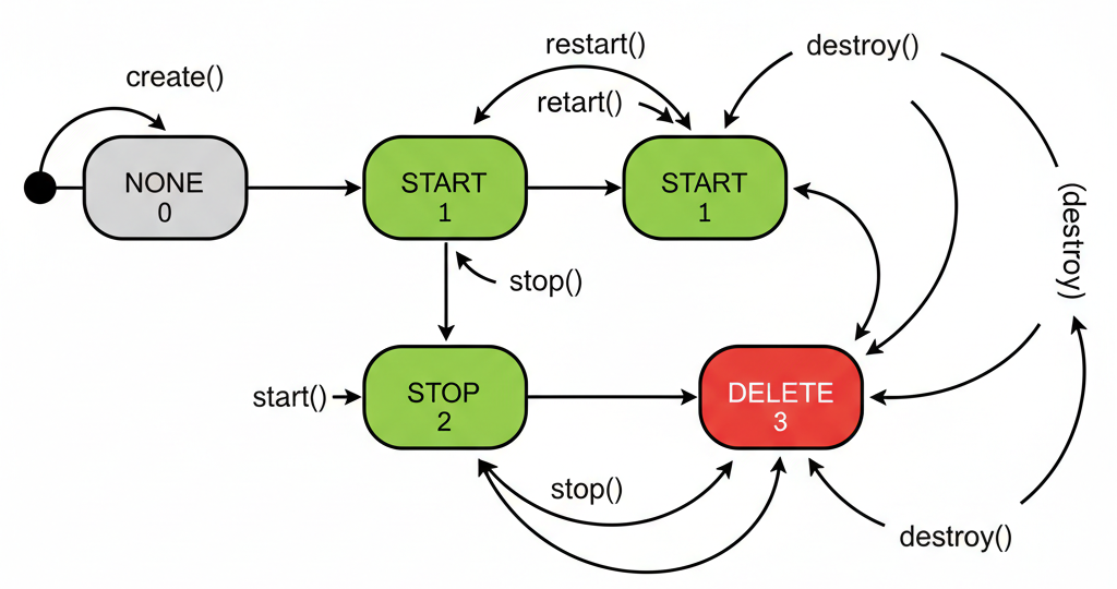
Timer nodes have four states and are managed through a state machine, with state transitions shown in the figure below.
When a timer is started, the node is inserted into the management linked list. The list is sorted in ascending order of timeout values.
When a node reaches its timeout, it is removed from the list, and the corresponding callback is executed.
If auto-reload is enabled for this node, it is reinserted into the list to restart timing.
enum {
    TLKAPI_TIMER_STATE_NONE = 0,    // Initial state
    TLKAPI_TIMER_STATE_START,       // Running state
    TLKAPI_TIMER_STATE_STOP,        // Stopped state
    TLKAPI_TIMER_STATE_DELETE,     // Pending deletion state
};
The node management linked list is sorted in ascending order of timeout values.
(3) Related API
Function Quick Reference:
| Function | API | Complexity |
|---|---|---|
| Create (static) | tlkapi_timer_createStatic |
O(1) |
| Create (dynamic) | tlkapi_timer_create |
O(1) + malloc |
| Start | tlkapi_timer_start |
O(n), insert |
| Restart | tlkapi_timer_reStart |
O(n), delete + insert |
| Stop | tlkapi_timer_stop |
O(n), delete |
| Destroy | tlkapi_timer_destroy |
O(n), delete + free/reset |
| Get next expiration time | tlkapi_timerList_getNextTimeUs |
O(1) |
| Main loop handler | tlkapi_timerList_handler |
O(k), where k is the number of expired timers |
Timer Creation:
tlkapi_timer_createStatic: Used to create a timer statically using a user-provided buffer.
/**
 * @brief           Statically create a timer (using provided buffer)
 * @param[in]       buffer - Pointer to TlkApiTimer_t structure to hold timer information
 * @param[in]       periodUs - Timer period (microseconds)
 * @param[in]       autoReload - Whether to automatically reload (non-zero for auto-reload)
 * @param[in]       CBEnter - Callback function to call when timer expires
 * @param[in]       usrArg - User argument to pass to callback function
 * @return          TLK_ENONE for success, other negative values for failure
 * @note            This function does not allocate memory, directly uses the passed buffer as timer storage space
 */
int32_t tlkapi_timer_createStatic(TlkApiTimer_t *buffer, uint32_t periodUs, uint32_t autoReload, TlkApiTimerCB_t CBEnter, void *usrArg);
tlkapi_timer_create: Used to create a timer dynamically with automatic internal memory allocation.
/**
 * @brief           Dynamically create a timer (allocates memory internally)
 * @param[out]      timerHandle - Pointer to store the created timer handle
 * @param[in]       periodUs - Timer period (microseconds)
 * @param[in]       autoReload - Whether to automatically reload (non-zero for auto-reload)
 * @param[in]       CBEnter - Callback function to call when timer expires
 * @param[in]       usrArg - User argument to pass to callback function
 * @return          TLK_ENONE for success, other negative values for failure
 * @note            This function allocates memory internally; need to call tlkapi_timer_destroy to release
 */
int32_t tlkapi_timer_create(TlkApiTimerHandle_t *timerHandle, uint32_t periodUs, uint32_t autoReload, TlkApiTimerCB_t CBEnter, void *usrArg);
The difference between the two creation methods lies in memory management. The first method requires the user to manage memory allocation. The second method uses automatic system allocation, and the memory is released when the timer is destroyed.
Timer Control:
tlkapi_timer_start: Starts a timer.
/**
 * @brief           Start a timer
 * @param[in]       list - Timer list pointer
 * @param[in]       timerHandle - Timer handle to start
 * @return          TLK_ENONE for success, other negative values for failure
 */
int32_t tlkapi_timer_start(TlkApiTimerList_t *list, TlkApiTimerHandle_t timerHandle);
tlkapi_timer_reStart: Restarts the timer. If the timer is running, it is reset and starts counting from zero.
/**
 * @brief           Restart a timer
 * @param[in]       list - Timer list pointer
 * @param[in]       timerHandle - Timer handle to restart
 * @return          TLK_ENONE for success, other negative values for failure
 * @note            If the timer is already running, it will be stopped and restarted
 */
int32_t tlkapi_timer_reStart(TlkApiTimerList_t *list, TlkApiTimerHandle_t timerHandle);
tlkapi_timer_stop: Stops the timer.
/**
 * @brief           Stop a timer
 * @param[in]       list - Timer list pointer
 * @param[in]       timerHandle - Timer handle to stop
 * @return          TLK_ENONE for success, other negative values for failure
 * @note            If the timer is executing its callback function, it will be automatically stopped after the callback finishes
 */
int32_t tlkapi_timer_stop(TlkApiTimerList_t *list, TlkApiTimerHandle_t timerHandle);
tlkapi_timer_destroy: Destroys the timer.
/**
 * @brief           Destroy a timer
 * @param[in]       list - Timer list pointer
 * @param[in]       timerHandle - Timer handle to destroy
 * @return          TLK_ENONE for success, other negative values for failure
 * @note            If the timer is executing its callback function, it will be automatically destroyed after the callback finishes
 */
int32_t tlkapi_timer_destroy(TlkApiTimerList_t *list, TlkApiTimerHandle_t timerHandle);
tlkapi_timer_setPeriod: Sets the timer period.
/**
 * @brief           Set timer period
 * @param[in]       list - Timer list pointer
 * @param[in]       timerHandle - Timer handle to set
 * @param[in]       periodUs - New timer period (microseconds)
 * @return          TLK_ENONE for success, other negative values for failure
 * @note            If the timer is running, it will reschedule the next expiration time
 */
int32_t tlkapi_timer_setPeriod(TlkApiTimerList_t *list, TlkApiTimerHandle_t timerHandle, uint32_t periodUs);
tlkapi_timer_isStarted: Checks whether the timer is started.
/**
 * @brief           Check if timer is started
 * @param[in]       timerHandle - Timer handle to check
 * @return          true if timer is started, false otherwise
 */
bool tlkapi_timer_isStarted(TlkApiTimerHandle_t timerHandle);
Timer Handling:
tlkapi_timerList_handler: Handles expired timers and invokes the corresponding callback functions.
/**
 * @brief           Process expired timers
 * @param[in]       list - Timer list pointer
 * @note            This function will call the callback functions of all expired timers
 */
void tlkapi_timerList_handler(TlkApiTimerList_t *list);
tlkapi_timerList_getNextTimeUs: Gets the time interval until the next timer expires, in microseconds.
/**
 * @brief           Get time until next timer expires (in microseconds)
 * @param[in]       list - Timer list pointer
 * @return          Time until next timer expires (in microseconds), or TLKOS_WAIT_FOREVER if no timers
 */
uint32_t tlkapi_timerList_getNextTimeUs(TlkApiTimerList_t *list);
(4) Usage Notes
- The minimum timer duration is approximately 50 microseconds (TLKAPI_TIMEOUT_MIN).
- The maximum timer duration is approximately 67 seconds (TLKAPI_TIMEOUT_MAX).
- It is not recommended to perform time-consuming operations in callback functions, as this may affect the handling of other timers.
- Timer control APIs (e.g., start, stop, destroy) can be safely called in timer callback functions.
- Dynamically created timers must be released using tlkapi_timer_destroy to free resources.
tlksys_timer Thread/Task Timer
The tlksys_timer module is a thread/task-level timer management module in the SDK. It is built on top of the tlkapi-layer tlkapi_timerList module and provides timer functionality for system tasks and threads.
This module associates timers with specific tasks via task IDs, allowing each task to independently manage its own timer set. Related APIs are defined in tlksys_timer.h.
This type of timer is intended for coarse-grained periodic task scenarios. For higher precision or higher priority timing requirements, tlkos_timer or hardware timers should be used instead.
Basic Principle:
Each task maintains its own timer list. The task structure (tlksys_task_t) contains a timerList field:
typedef struct {
    uint16_t taskID;
    uint16_t state;
    TlkApiTimerList_t timerList;  // Timer list for each task
    const tlksys_task_cfg_t *pCfgs;
    TlkOsTaskHandle_t taskHandle;
} tlksys_task_t;
In RTOS mode, the system invokes tlkapi_timerList_handler within each task’s main loop to process timers attached to that task and execute callbacks of expired timers.
After completing all processing in the current task cycle, the task calls tlkapi_timerList_getNextTimeUs to obtain the thread blocking duration, and then calls tlksys_task_waitEvent to wait for the next wake-up cycle.
Related Notes:
- The
tlksys_task_waitEventfunction is used to put the thread into the blocked state. The thread transitions to the ready state either when subscribed events (e.g., semaphores) wake it up or when the timeout expires. - If no timers have been started for the thread, the blocking duration is set to
TLKOS_WAIT_FOREVER, and the thread can only be awakened by events. - Timer handling is based on the RTOS blocking-delay scheduling mechanism. If a higher-priority thread is running, expired timers remain pending until the current thread is scheduled for execution.
- After the timer list associated with a task is modified,
tlksys_task_setEvtis called to wake up the corresponding thread so that its blocking duration can be updated.
static void tlksys_template_task(void *arg)
{
    //Initialization code
    while(1){
        // ... Other processing
        tlkapi_timerList_handler(&task->timerList);  // Handle expired timers
        // ... Other processing
        uint32_t blockTimeMs = tlkos_task_nextIntvUsToMs(tlkapi_timerList_getNextTimeUs(&task->timerList),1,TLKOS_WAIT_FOREVER);
        tlksys_task_waitEvent(task->taskID,blockTimeMs);
    }
}
In bare-metal mode, all tasks run within a single main loop. Each task polls its registered events and processes its timer handler.
When no events need to be processed, the system enters the idle task. The idle task obtains the minimum timeout value among all tasks and uses it to determine the next wake-up point before entering a low-power state (e.g., WFI or suspend mode).
void tlksys_task_handler(void)
{
    for (size_t index = 0; index < TLKSYS_TASKID_MAXNUM; index++) {
        tlksys_task_t *pTask = &sTlkSysTaskList[index];
        //... Logic omitted for brevity
        tlkos_event_wait(sTlkTaskEvtTabHandles[index],0);
        tlkapi_timerList_handler(&pTask->timerList);
        //... Logic omitted for brevity
    }
    tlksys_task_idleTask(); //Idle task for low-power operation
}
Thread Safety Mechanism in RTOS Mode:
The tlksys_timer module ensures thread safety through mutexes:
- Each task has a dedicated mutex.
- The mutex is acquired before performing timer operations.
- The mutex is released after the operation is completed.
- This ensures data consistency when multiple threads concurrently operate on timers associated with the same task.
Usage Example:
// Assume that the timer is used in the SYSTEM thread
static TlkApiTimer_t sMyTimer;

static void myTimerCB(TlkApiTimerHandle_t handle, void* userArg)
{
    // Process timer events
    // Perform task-specific operations here
    (void) handle;
    (void) userArg;
    //1-second periodic timer with auto-reload
    tlk_printf("print log per 1s");
    if(something_happened){
        //Pseudocode: Stop the timer when certain UI events occur
        tlksys_timer_stop(TLKSYS_TASKID_SYSTEM, &sMyTimer);
    }
}

// Create a timer during task initialization
void user_demo_init(void)
{
    tlksys_timer_createStatic(TLKSYS_TASKID_SYSTEM, &sMyTimer, 1 * 1000 * 1000, 1,
                             myTimerCB, NULL); // 1-second periodic timer
    tlksys_timer_start(TLKSYS_TASKID_SYSTEM, &sMyTimer);
}
Summary:
The tlksys_timer module extends the timer functionality provided by the tlkapi-layer in the following ways:
- Task Isolation: Each task maintains an independent timer list, preventing timer conflicts and ensuring that timer callbacks are executed according to the task's original priority.
- Thread Safety: Mutexes are used to ensure safe access in multi-threaded environments.
- Event-Driven Processing: Timer operations automatically trigger task events to ensure timely processing.
- Simplified Interface: Provides a more concise API while hiding underlying implementation details.
tlkos_timer System Timer
The tlkos_timer module is a timer management component in the SDK's Operating System Abstraction Layer (OSAL).
It provides different implementations for bare-metal and RTOS environments.
The module exposes a unified API to upper-layer applications and hides the differences in the underlying implementations.
API Overview:
| API Function | Bare-Metal Implementation | RTOS Implementation |
|---|---|---|
| tlkos_timer_create | Based on tlkapi_timer_create | Based on RTOS APIs, such as FreeRTOS xTimerCreate |
| tlkos_timer_destroy | Based on tlkapi_timer_destroy | Based on RTOS APIs, such as FreeRTOS xTimerDelete |
| tlkos_timer_start | Based on tlkapi_timer_start | Based on RTOS APIs, such as FreeRTOS xTimerStart |
| tlkos_timer_stop | Based on tlkapi_timer_stop | Based on RTOS APIs, such as FreeRTOS xTimerChangePeriod |
| tlkos_timer_setPeriod | Based on tlkapi_timer_setPeriod | Based on RTOS APIs, such as FreeRTOS xTimerStart |
| tlkos_timer_startFromISR | Not supported | Based on RTOS APIs, such as FreeRTOS xTimerStartFromISR |
Implementation:
In a bare-metal environment, the tlkos_timer module is built on top of the software timer list in the hardware timer tlkapi-layer.
- Use the MCU's
Timer1peripheral as the system tick source. - Use the tlkapi-layer
TlkApiTimerList_tas the software timer manager. - Process software timers through hardware timer interrupts.
In an RTOS environment, the tlkos_timer module directly wraps the RTOS timer APIs.
In bare-metal mode, timer processing is driven by the Timer1 peripheral interrupt. In RTOS mode (using FreeRTOS as an example), timer processing is handled by the timer service task, which runs at a very high priority. Although the implementations differ, both rely on high-priority execution contexts to ensure timely timer processing and preemption.
Usage Example:
// Timer callback function
static void keyscan_timer_callback(TlkOsTimerHandle_t timerHandle, void *pUsrArg)
{
    (void) timerHandle;
    (void) pUsrArg;
    key_scan();
}

// Create and start the timer
void example_key_scan_timer_init(void)
{
    TlkOsTimerHandle_t timerHandle;
    tlkos_timer_create("key_sacn_timer", 10, 1, keyscan_timer_callback, NULL, &timerHandle);
    tlkos_timer_start(timerHandle);
}
Hardware Timers
The following table summarizes the hardware timer resources used by the SDK.
| Hardware Resource | SDK Usage | Status ([x] In Use, [ ] Available) |
|---|---|---|
stimer |
Clock source for the wireless protocol stack controller scheduler | Single-core devices [x], application core on dual-core devices (D25F) [ ] |
timer0 |
Provides high-precision periodic timing for audio tasks | Audio enabled [x], audio disabled [ ] |
timer1 |
Trigger source for the bare-metal tlkos timer system |
RTOS disabled [x], RTOS enabled [ ] |
mtimer |
RTOS system tick source | RTOS disabled [ ], RTOS enabled [x] |
Users may use the hardware timers listed above to implement high-precision timing as needed.
Debug Methods
The Telink SDK provides multiple debugging methods, including the printf API, the hierarchical logging system, and other debugging mechanisms.
Use the RISC-V TDB tool via USB, or the telinkdualmodeaudiotool via UART, to view messages printed by the printf API.
The following sections describe the printf API in detail.
Telink Print APIs
(1) Basic Printf APIs
tlkapi_printf: Primary formatted output function.
#define tlkapi_printf(en, fmt, ...)
    if (en) {
        tlk_printf(fmt, ##__VA_ARGS__);
    }
-
Parameters:
en: Enable flag. Log output is enabled when the value is non-zero.fmt: Format string, same as standard Cprintf....: Variable argument list.
-
Usage Scenario: General-purpose log output. The first parameter can be used to easily enable or disable logging.
(2) Log Level APIs
The SDK provides five levels of log output functions, each associated with a specific log level:
#define tlkapi_warn(flags, pSign, format, args...)  // Warning level with <WARN> tag
#define tlkapi_info(flags, pSign, format, args...)  // Info level with <INFO> tag
#define tlkapi_trace(flags, pSign, format, args...) // Trace level with <TRACE> tag
#define tlkapi_fatal(flags, pSign, format, args...) // Fatal error with <FATAL> tag
#define tlkapi_error(flags, pSign, format, args...) // Error level with <ERROR> tag
-
Parameters:
flags: Debug flags used to control whether logging is enabled.pSign: Signature identifier used to distinguish different modules.formatandargs: Format string and corresponding arguments.
-
Usage Scenario: Logs categorized by severity level, making it easier to filter and locate issues.
(3) Array Data Printing APIs
#define tlkapi_array(flags, pSign, format, pData, dataLen)
    tlkdbg_array(flags, pSign, format, (uint8_t *)pData, dataLen)
-
Parameters:
pData: Pointer to the data array.dataLen: Length of the data.
-
Usage Scenario: Used for printing binary data, buffer contents, etc.
(4) High-Efficiency Data Transmission APIs
#define tlkapi_send_string_data(en, str, pData, len)  // Mixed mode for sending strings and data
#define tlkapi_send_string_u32s(en, str, ...)         // Send string and multiple uint32_t values
#define tlkapi_send_string_u8s(en, str, ...)          // Send string and multiple uint8_t values
#define tlkapi_sendStr(en, pStr)                      // Send string only
#define tlkapi_sendData(en, pStr, pData, dataLen)     // Send string and data
- Features: These APIs send logs to a FIFO buffer instead of outputting them immediately. The logs are not printed until they are processed by
debug_handler. - Usage Scenario: Efficient log recording, suitable for high-frequency call scenarios.
(5) DSP Debug APIs
For the DSP module, the SDK provides dedicated debugging functions:
#define dsp_log_printf(...)  // DSP general log output

// DSP level-based log output
#define dsp_printf_warn(module, ...)   // Warning level
#define dsp_printf_debug(module, ...)  // Debug level
#define dsp_printf_error(module, ...)  // Error level
#define dsp_printf_info(module, ...)   // Info level

// DSP string output
#define dsp_print_str_warn(module, str)
#define dsp_print_str_debug(module, str)
#define dsp_print_str_error(module, str)
#define dsp_print_str_info(module, str)
-
Parameters:
module: Module flag used to control output.- The formatting parameters are similar to standard
printf.
Debug Level and Debug Flag Control
The SDK defines five debug levels and multiple debug flags for fine-grained control over log output types:
typedef enum
{
    TLKAPI_DEBUG_LEVEL_LEVEL1 = TLKAPI_DBG_ASSERT_FLAG | TLKAPI_DBG_FATAL_FLAG | TLKAPI_DBG_ERROR_FLAG |
                                TLKAPI_DBG_WARN_FLAG | TLKAPI_DBG_INFO_FLAG | TLKAPI_DBG_TRACE_FLAG |
                                TLKAPI_DBG_ARRAY_FLAG,  // Print all logs
    TLKAPI_DEBUG_LEVEL_LEVEL2 = TLKAPI_DBG_ASSERT_FLAG | TLKAPI_DBG_FATAL_FLAG | TLKAPI_DBG_ERROR_FLAG |
                                TLKAPI_DBG_WARN_FLAG | TLKAPI_DBG_INFO_FLAG,  // Disable TRACE and ARRAY logs
    TLKAPI_DEBUG_LEVEL_LEVEL3 = TLKAPI_DBG_ASSERT_FLAG | TLKAPI_DBG_FATAL_FLAG | TLKAPI_DBG_ERROR_FLAG |
                                TLKAPI_DBG_WARN_FLAG,  // Output only error and warning logs
    TLKAPI_DEBUG_LEVEL_LEVEL4 = TLKAPI_DBG_ASSERT_FLAG | TLKAPI_DBG_FATAL_FLAG | TLKAPI_DBG_ERROR_FLAG,
    TLKAPI_DEBUG_LEVEL_LEVEL5 = TLKAPI_DBG_ASSERT_FLAG | TLKAPI_DBG_FATAL_FLAG,
} TLKAPI_DEBUG_LEVEL_ENUM;
- Usage: Select the debug level by setting corresponding macros or configuration options.
#define TLKAPI_DBG_WARN_FLAG   0x02  // Warning log
#define TLKAPI_DBG_INFO_FLAG   0x04  // Info log
#define TLKAPI_DBG_TRACE_FLAG  0x08  // Trace log
#define TLKAPI_DBG_ERROR_FLAG  0x10  // Error log
#define TLKAPI_DBG_FATAL_FLAG  0x20  // Fatal error
#define TLKAPI_DBG_ARRAY_FLAG  0x40  // Array data
#define TLKAPI_DBG_ASSERT_FLAG 0x80  // Assertion flag
#define TLKAPI_DBG_FLAG_ALL    0xFE  // All logs
Debug Output Configuration
(1) Debug Log Global Switch
#define TLK_DEBUG_ENABLE 1 // 1: Enable debug features, 0: Disable all debug features
- Function: Controls the global switch of the entire SDK debug system.
- Location: Typically defined in
app_config.h. - Effect: When set to 0, all debug APIs (including
printfand level-based logs) are disabled, effectively reducing firmware size.
(2) USB/UART Debug Output Selection
The SDK supports multiple debug output methods, which can be selected as needed.
USB Debug Output:
#define TLKDBG_CFG_UDB_LOG_ENABLE 1 // 1: Enable USB debug output
- Function: Outputs debug logs via USB interface.
- Applicable scenarios: When high-speed debug output is required, or no UART interface is available.
- Tool: Logs can be viewed via USB using the
telinkdualmodeaudiotool.
HCI UART Debug Output:
#define TLKDBG_CFG_HPU_LOG_ENABLE 1 // 1: Enable HCI UART debug output
- Function: Outputs debug logs via the HCI UART interface.
- Applicable scenarios: When an HCI UART interface is available.
Hardware UART Debug Output:
#define TLKDBG_CFG_HWU_LOG_ENABLE 1 // 1: Enable hardware UART debug output
- Function: Outputs debug logs via a specified hardware UART interface.
Configuration options:
// Select the UART port
#define TLKAPI_DEBUG_UART_PORT DBG_UART_PORT0  // Optional: DBG_UART_PORT0 or DBG_UART_PORT1

// Select the UART channel based on the port
#if (TLKAPI_DEBUG_UART_PORT == DBG_UART_PORT0)
    #define DEBUG_UART_CHANNEL UART0
#elif (TLKAPI_DEBUG_UART_PORT == DBG_UART_PORT1)
    #define DEBUG_UART_CHANNEL UART1
#endif

// Configure UART pins
#define TLKAPI_DEBUG_UART_TX_PIN GPIO_FC_PD3  // TX pin
#define TLKAPI_DEBUG_UART_RX_PIN GPIO_FC_PA5  // RX pin

// Configure baud rate
#define TLKAPI_DEBUG_UART_BAUDRATE 1000000  //  Default: 1 Mbps
Other Debug Methods
(1) Assertion Debugging
In non-NDEBUG mode, the SDK provides assertion functionality:
#ifndef NDEBUG
void __assert_func(const char *f, int l, const char *af, const char *e)
{
    tlkapi_printf(1, "assert error: FILE:%s, LINE: %d", f, l);
    TLKSTK_ERROR_DEBUG(1, 0xFF300000);
    while(1); // Infinite loop for debugging purposes
}
#endif
(2) GPIO Debugging
The SDK supports GPIO-based simple debug signal output:
#define DBG_JUNWEI_CHN12_LOW    gpio_write(GPIO_CHN12, 0)
#define DBG_JUNWEI_CHN12_HIGH   gpio_write(GPIO_CHN12, 1)
#define DBG_JUNWEI_CHN12_TOGGLE gpio_toggle(GPIO_CHN12)
// Similarly, debug macros are defined for other GPIO channels.
- Usage Scenario: A logic analyzer or oscilloscope can be used to monitor GPIO states for analyzing code execution flow and timing.
For RF module debugging, the rf_set_ble_bb_debugport() function can be used to map RF module status to corresponding GPIO pins, making it easier to analyze signals using an oscilloscope or logic analyzer.
(3) N22 Dual-Core Debugging
For chips based on the N22 dual-core architecture (e.g., TL751x series), the SDK provides dedicated dual-core debugging support.
Dual-Core Mode:
#define MCU_DUAL_CORE_ENABLE 1 // 1: Enable dual-core mode
- Function: Controls whether dual-core mode is enabled.
- Effect: When enabled, the system runs both the D25F core and the N22 core simultaneously.
N22 Core Log Output Switch:
#define TLK_SM_LOG_ENABLE 1 // 1: Enable N22 core log output
- Function: Controls the log output feature of the N22 core.
- Working principle: Logs generated by the N22 core are transmitted to the D25F core via shared memory, and then centrally output by the D25F core.
Core Identification Macro:
// Determine whether the current code is running on an N22 core
#if defined(MCU_CORE_N22)
    // N22 core-specific code
#else
    // D25F core-specific code
#endif
- Function: Distinguishes code running on different CPU cores
- Other related macros:
MCU_CORE_TL751X_N22- N22 core on the TL751x chip
(4) System Crash Handling
The SDK provides information collection and output functionality for system crash handling:
void tlkos_crash(const TlkOsCrashInfo_t * info)
{
    // Collect and output crash information
    tlkos_crash_printAPI("[OS_CRASH]**********[OS_CRASH]");
    if(info->detailInfo){
        tlkos_crash_printAPI(info->detailInfo);
    }
    // Output core information
    const char * log = tlkos_debug_getCoreInfo();
    while(log)
    {
        tlkos_crash_printAPI(log);
        log = tlkos_debug_getCoreInfo();
    }
    while(1); // Infinite loop to preserve the crash state
}
(5) Read Memory Information Using the BDT Tool
-
The Memory Access tool integrated in BDT supports reading and modifying RAM and Flash memory contents at runtime.
-
The Tdebug feature integrated in BDT (requires a
.lstfile) supports viewing and debugging system status at runtime, including register values, memory contents, and more.
Usage Examples
(1) Basic Log Output
// Output normal logs
tlkapi_printf(1, "System initialized, version: %s\n", "v1.0.0");

// Output error logs
tlkapi_error(DEBUG_FLAG, MODULE_SIGN, "Failed to initialize hardware, error: %d\n", error_code);

// Print array data
uint8_t buffer[16] = {1, 2, 3, 4};
tlkapi_array(DEBUG_FLAG, MODULE_SIGN, "Received data:", buffer, 4);
(2) Control Debug Levels
// In user_config.h or other configuration files
#define TLKAPI_DEBUG_LEVEL TLKAPI_DEBUG_LEVEL_LEVEL2  // Set to level 2
(3) Configure Debug Output Method
// Configure UART debugging
#define TLK_DEBUG_ENABLE 1
#define TLKDBG_CFG_HWU_LOG_ENABLE 1
#define TLKAPI_DEBUG_UART_PORT DBG_UART_PORT0
#define TLKAPI_DEBUG_UART_TX_PIN GPIO_PD3
#define TLKAPI_DEBUG_UART_RX_PIN GPIO_PA5
#define TLKAPI_DEBUG_UART_BAUDRATE 115200

// Or configure USB debugging
#define TLK_DEBUG_ENABLE 1
#define TLKDBG_CFG_UDB_LOG_ENABLE 1
(4) Configure Dual-Core Debugging
// Enable dual-core debugging
#define TLK_DEBUG_ENABLE 1
#define MCU_DUAL_CORE_ENABLE 1
#define TLK_SM_LOG_ENABLE 1  // Enable N22 core logging

// Example log output on the N22 core
#if defined(MCU_CORE_N22)
    tlkapi_info(DEBUG_FLAG, "N22_CORE", "N22 core initialized successfully\n");
#endif
(5) DSP Logging
// DSP module log output
#define DSP_AUDIO_MODULE_ENABLE 1  // Enable module debugging where needed

dsp_printf_info(DSP_AUDIO_MODULE_ENABLE, "Audio stream started, sample rate: %d Hz\n", 44100);
Memory Allocation
(1) Description
This SDK provides dynamic memory management interfaces, including commonly used APIs such as malloc, free, and realloc. Two sets of memory management interfaces are provided: system-level memory allocation interfaces and lower-level general-purpose memory allocation interfaces.
-
The former interfaces are defined in
tlkos_api/tlkos_memory.h. These interfaces support both custom bare-metal and native FreeRTOS memory management. When FreeRTOS is enabled in the application, the system automatically switches to the native FreeRTOS memory management interfaces by default. -
The latter interfaces are defined in
tlklib/mem/tlkmem1.h. These memory allocation and management interfaces can be used to dynamically define memory blocks required by the application, helping prevent system issues caused by insufficient memory or memory fragmentation.
(2) Constraints
N/A
(3) API Description
Memory Pool Data Structure Definition:
struct tlkmem1_unit_s
{
    struct tlkmem1_unit_s *prev;        /*Pointer to the previous block of the current memory block*/
    struct tlkmem1_unit_s *next;        /*Pointer to the next block of the current memory block*/
    uint32_t               size : 31;   /*Defined size of the memory block*/
    uint32_t               used : 1;    /*Flag indicating whether the memory block is used*/
};
Memory Pool APIs:
- Memory pool initialization API:
int tlkmem1_init(void *pBuffer, uint32_t buffLen);
- Memory pool deinitialization (cleanup) APIs: The following two APIs provide identical functionality; either can be used.
void tlkmem1_deinit(void *mem);
void tlkmem1_clean(void *mem);
- Memory print API: Outputs the actual contents of a specified memory region.
void tlkmem1_print(void *mem);
- Memory allocation API: Allocates a memory block of size
sizefrom the memory pool.
void *tlkmem1_malloc(void *mem, uint32_t size);
- Memory allocation API: Allocates a memory block of size
sizefrom the memory pool and clears it to zero.
void *tlkmem1_calloc(void *mem, uint32_t size);
- Memory reallocation API: Reallocates a memory block of size
sizefrom the memory pool.
void *tlkmem1_realloc(void *mem, void *ptr, uint32_t size);
- Memory free API: Frees a memory block in the memory pool.
int tlkmem1_free(void *mem, void *ptr);
Predefined Memory Pools in the System:
| Memory Pool | Size (Bytes) | Purpose |
|---|---|---|
| sTlkOsBareMetalMemBuffer | 8 * 1024 | Stack memory for bare-metal or RTOS systems |
| sTlkMdiAudMemBuffer | 64 * 1024 | Audio task usage |
| sTlkBtMemBuffer | 13 * 1024 | Bluetooth Host task usage |
| ... | ... | ... |
Note
- The above lists the always-on memory pools in the system. Other pools (non-always-on, debug-related, or disabled by default) are not described in this document.
Memory Pool Flexible Usage:
- The sizes of
sTlkOsBareMetalMemBufferandsTlkBtMemBufferare not recommended to be modified, as they have been optimized to reasonable values. In contrast,sTlkMdiAudMemBuffercan be adjusted based on the memory requirements of the audio algorithms used in the application. Its size can be redefined through the macroTLKMDI_AUDMEM_TOTAL_SIZE. - The memory pool used by the audio task can be controlled via the macro
TLKMW_AUDIO_MEMPOOL_INDEPENDENT. When this feature is disabled, the memory required by the Audio task is allocated from the system memory poolsTlkOsBareMetalMemBuffer. In this case, the size ofsTlkOsBareMetalMemBuffermust be adjusted to at least 72 KB (64 KB + 8 KB).- Although this mechanism appears to be a simple merge of memory pools, it can effectively reduce memory usage in non-audio scenarios where the system memory pool needs to be expanded.
- For example, if the OTA feature requires 30 KB of system memory, the original design would require at least 94 KB in total (30 KB + 64 KB). However, since OTA and Audio do not run simultaneously and OTA requires less memory than the audio task, the merged 72 KB pool can be used instead, reducing overall memory consumption.
Flash Address Definition
Each Flash capacity has a base address (BASE_ADDR). All other regions are calculated as offsets relative to this base address.
| Flash Capacity | Base Address (BASE_ADDR) |
|---|---|
| 1M | 0xF2000 |
| 2M | 0x1EA000 |
| 4M | 0x3EA000 |
| 8M | 0x7EA000 |
| 16M | 0xFEA000 |
1M Flash Memory Map (Special Layout)
| Region | Offset from Base Address | Address Range | Size | Description |
|---|---|---|---|---|
| SDP ATT Information | +0x0000 | 0xF2000 - 0xF3FFF | 8KB | GATT Service Discovery Cache |
| SMP Pairing Information | +0x2000 | 0xF4000 - 0xF7FFF | 16KB | BLE pairing key information |
| Secure Boot Region | +0x6000 | 0xF8000 - 0xFB000 | 12KB | Secure boot code and signature |
| Calibration Data | +0xC000 | 0xFE000 - 0xFEFFF | 4KB | Production calibration parameters |
| MAC Address Storage | +0xD000 | 0xFF000 - 0xFFFFF | 4KB | BLE/BT MAC address storage |
2M+ Flash Memory Map (Standard Layout)
| Region | Offset from Base Address | Address Range | Size | Description |
|---|---|---|---|---|
| SDP ATT Information | +0x0000 | 0x*EA000 - 0x*EBFFF | 8KB | GATT Service Discovery Cache |
| SMP Pairing Information | +0x2000 | 0x*EC000 - 0x*EFFFF | 16KB | BLE pairing key information |
| Reserved Region | +0x6000 | 0x*F0000 - 0x*F7FFF | 32KB | Reserved / Unused Region |
| Secure Boot Region | +0xE000 | 0x*F8000 - 0x*FB000 | 12KB | Secure boot code and signature |
| Calibration Data | +0x14000 | 0x*FE000 - 0x*FEFFF | 4KB | Production calibration parameters |
| MAC Address Storage | +0x15000 | 0x*FF000 - 0x*FFFFF | 4KB | BLE/BT MAC address storage |
User-Defined Memory Region Allocation
These regions are defined using TLK_CFG_FLASH_* macro offsets and managed using tinysql. Users can add custom regions by defining additional macros, ensuring no overlap with existing regions.
The actual address is calculated as:
Actual address = offset + flash_full_size - 0x100000.
| Region | Offset from Base Address | Size | Description |
|---|---|---|---|
| PBAP List | 0xC0000 | 64KB | Phone Book Access Profile data |
| User Settings | 0xD0000 | 8KB | User configuration parameters |
| Bluetooth Device Information | 0xD2000 | 8KB | Classic Bluetooth device information |
| LE Device Information | 0xD4000 | 8KB | BLE device information |
| Audio Configuration | 0xD8000 | 8KB | Audio parameter configuration |
MAC Address Storage Region
- Size: 4 KB
- Purpose: Stores BLE and BT MAC addresses
- Internal Layout:
BASE_ADDR + 0x0000 ~ BASE_ADDR + 0x00FF: BLE MAC address (256 bytes)BASE_ADDR + 0x0100 ~ BASE_ADDR + 0x01FF: BT MAC address (256 bytes)- Remaining space: Reserved or used for additional MAC-related configurations
Calibration Data Storage Region
- Size: 4 KB
- Purpose: Production and test calibration data
Calibration Data Internal Structure:
#define CALIB_OFFSET_CAP_INFO        0x00   // Frequency offset calibration information
#define CALIB_OFFSET_TP_INFO         0x40   // Touchscreen calibration information
#define CALIB_OFFSET_ADC_VREF        0xC0   // ADC reference voltage calibration
#define CALIB_OFFSET_FIRMWARE_SIGNKEY 0x180 // Firmware signature key
Multi-Core Chip Architecture Overview
-
A multi-core system integrates multiple independent processor cores within a single chip. Taking the
TL751xplatform as an example, it contains three processor cores:D25F,N22, andDSP. Among them,D25FandN22areRISC-V-based cores, while theDSPis based on the HiFi5 architecture, forming a heterogeneous three-core design. Each core can independently fetch instructions, execute computations, and process data, enabling parallel task execution and significantly improving performance in multi-tasking and multi-threading scenarios. -
The SDK is adapted for multiple key projects on the
TL751xplatform. Therefore, this chapter uses theTL751xplatform as the reference example for description.
Function and Architecture
The following diagram illustrates the architecture and working scenarios of different cores in the current multi-core chip system:
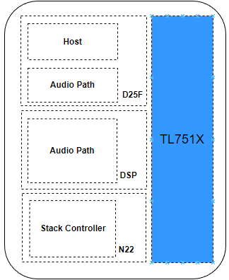
-
D25F: A high-performance 32-bit RISC-V CPU core responsible for running Host-related tasks.- The
D25Ffeatures a 5-stage pipeline, branch prediction, and an integrated floating-point unit, enabling efficient system-level processing. - In practical applications, it acts as the Host core, capable of running third-party operating systems such as FreeRTOS.
- It is also responsible for user application development, system resource scheduling, and complex peripheral management, and works with the
DSPto handle upper-layer audio control logic, significantly improving system flexibility for audio applications.
- The
-
N22: TheN22is an entry-level, high-efficiency RISC-V core designed for protocol stack execution.- It achieves a balance between low power consumption and high performance through a streamlined architecture. It performs well in processing high-throughput protocol packets, with low energy consumption and high code density.
- It is therefore dedicated to protocol stack execution and low-level wireless communication tasks such as signal transmission and reception control.
-
DSP: The
DSPis responsible for audio signal processing.- It supports a high audio sampling rate of up to 768 kHz and 24-bit depth. Together with a high-performance codec, it ensures high-fidelity audio output.
- It also supports advanced audio algorithms such as voice wake-up and microphone noise reduction, meeting the core requirements of wireless audio applications.
Performance Overview
The following shows the performance results of the D25F and N22 cores in the CoreMark and Dhrystone benchmarks:
Note
- Since the DSP is based on the HiFi5 architecture, MCU-oriented benchmarking tools such as CoreMark and Dhrystone cannot accurately reflect DSP performance. Therefore, DSP results are not included.
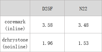
Resource Overview
The following shows the memory resource allocation of the TL751x platform:
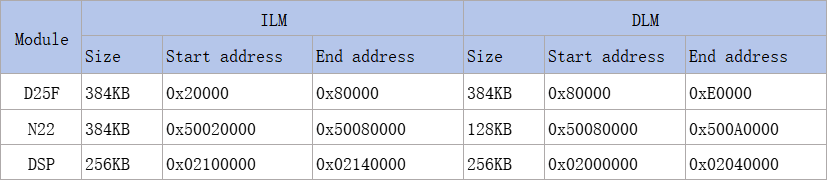
Communication Mechanisms
This SDK provides two primary inter-core communication mechanisms: mailbox-based communication and shared-memory communication.
(1) Mailbox Communication
- Mailbox communication is essentially a hardware-accelerated inter-core IPC mechanism. Its key characteristics are: “small payload” (the
TL751xplatform currently supports 2-word payload per transaction), “hardware interrupt-driven”, and “low-latency” message transfer. - On the
TL751xmulti-core chip, Telink provides a full-duplex mailbox communication channel, allowing any core to initiate communication. This ensures reliable message exchange without blocking or contention issues. - The mailbox communication scenario among the three cores is illustrated below:
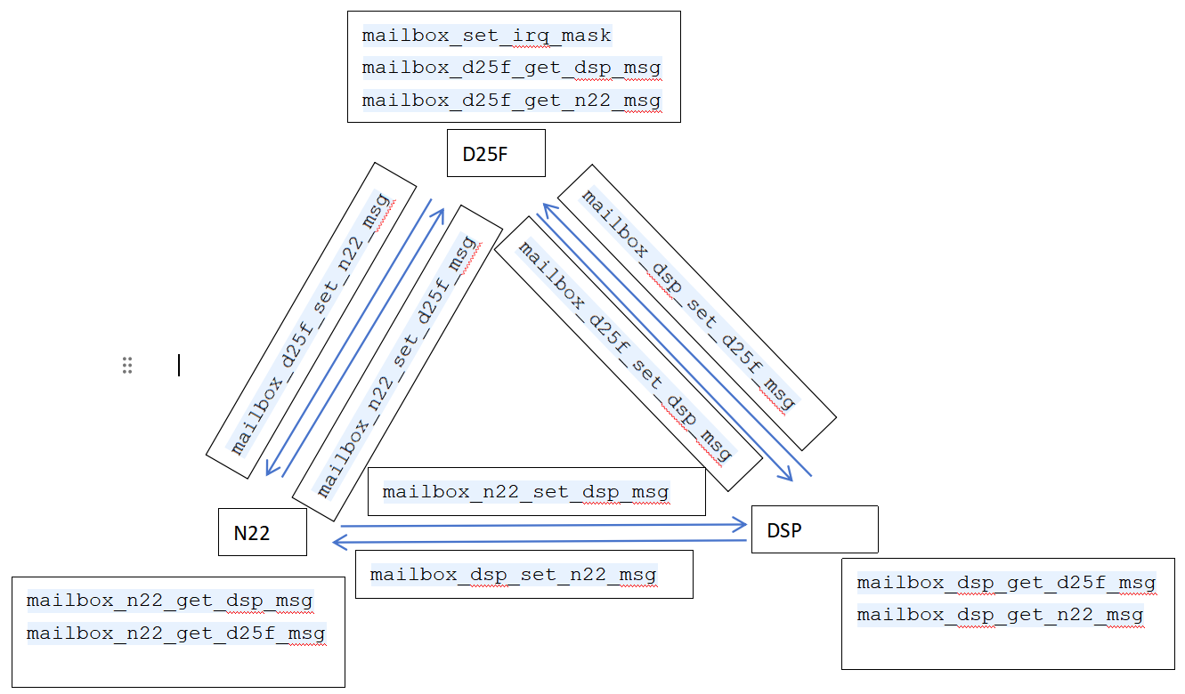
- Mailbox channels between the
D25F,N22, andDSPcores are defined for each core pair with directional communication. In total, there are six mailbox interrupt types:
typedef enum
{
    FLD_MAILBOX_D25F_TO_DSP_IRQ = BIT(0),
    FLD_MAILBOX_DSP_TO_D25F_IRQ = BIT(1),
    FLD_MAILBOX_D25F_TO_N22_IRQ = BIT(2),
    FLD_MAILBOX_N22_TO_D25F_IRQ = BIT(3),
    FLD_MAILBOX_N22_TO_DSP_IRQ = BIT(4),
    FLD_MAILBOX_DSP_TO_N22_IRQ = BIT(5),
} mailbox_irq_status_e;
- Usage example:
N22sends data toD25Fvia themailbox_n22_set_d25f_msgAPI. After transmitting a 2-wordmsg_wordpayload,D25Ftriggers the interruptFLD_MAILBOX_N22_TO_D25F_IRQ.D25Fcan then retrieve the data within the interrupt handler using themailbox_d25f_get_n22_msgAPI. OnceD25Freads the last byte of the final word, the hardware automatically clears the interrupt flag.
/* N22 */
unsigned int msg_word[2] = {0x01, 0x02};
mailbox_n22_set_d25f_msg(&msg_word[0]);

/* D25F */
unsigned int recv_msg_word[2] = {0, 0};
mailbox_d25f_get_n22_msg(&recv_msg_word[0]);
(2) Shared Memory
The Telink Shared Memory is designed to support variable-length data transfers, offering high memory utilization and strong flexibility.
As the primary core, D25F uses its own SRAM resources for shared memory. As shown in the code snippet below, during the power-on stage, D25F initializes and allocates memory for different inter-core communication channels via the corresponding APIs.
During system startup, D25F and N22 perform inter-core synchronization through a tlkipc_service_coreInfo_sync interface, including the exchange of shared-memory FIFO channel addresses. D25F stores this inter-core configuration information in a s_tlkipc_service_coreInfo control block and shares it with N22 via the mailbox mechanism, enabling subsequent inter-core synchronization operations.
int tlk_multi_core_communication_init(void)
{
    /* Initialize the mailbox message module */
    tlk_mailbox_service_init();
    /* Initialize shared memory */
    tlk_share_memory_service_init();
    /* Initialize inter-core synchronization */
    return tlkipc_service_coreInfo_sync();
}
The following example illustrates shared memory usage and implementation through an inter-core HCI command interaction between D25F and N22.
/* D25F initializes the relevant HCI and allocates memory */
share_memory_fifo_init(&sTlkSmFifo[MAIN_CORE_HCI_TX],mainCoreHciTxBuffer, TLK_SM_HCI_TX_BUFFER_SIZE);

/* The N22 core obtains the corresponding shared-memory FIFO address via the `spTlkSmFifo` control block, and registers a callback function that is triggered when shared-memory data is received */
share_memory_register_fifo_receive_cb(spTlkSmFifo[CONTROLLER_CORE_HCI_RX],controllerCoreHciRxCb);
If the application issues a BT HCI command on D25F, the command is routed through a series of message dispatch processes and is ultimately passed as a parameter to the following interface:
/* The BT HCI command issued by `D25F` is ultimately dispatched through multiple layers and written into the HCI FIFO defined in shared memory*/
tlk_sm_ret_e retSts = share_memory_data_push(&sTlkSmFifo[MAIN_CORE_HCI_TX],type,data,dataLen);

/* If the N22 core needs to subscribe to and receive BT HCI messages via shared memory, it must register the corresponding receive callback function*/
tlk_n22_register_hci_receive_cb(TLK_SHARE_MEMORY_MESSAGE_TYPE_BT, hci_rx_cb);

/* After completing callback registration, the N22 core can process received messages within its shared-memory loop handler*/
share_memory_data_popAll(spTlkSmFifo[CONTROLLER_CORE_HCI_RX]);
The example above briefly introduces the practical usage of shared memory in this SDK. In addition, shared memory also supports another mechanism: after a shared-memory message is sent, a mailbox is used to notify the peer core to retrieve the message in a timely manner. This mechanism is currently supported only for the N22 -> D25F direction.
This is because N22, as the controller core, continuously handles communication with external devices and must promptly forward received messages to the host core (D25F) for processing. Therefore, this notification mechanism is introduced to improve communication efficiency in this specific scenario.
Multi-Core Boot Process
In the TL751x multi-core architecture, D25F is the primary control core. After chip power-on, the D25F core is initialized first and completes its own system initialization sequence. It then uses the DMA module to transfer code to N22 or DSP and perform a series of boot operations, including the startup of the cores.
(1) N22 Boot
As described above, the N22 core is started under the control of the D25F core. The boot process includes the following steps:
1) N22 initialization: call the API
void sys_n22_init(unsigned int addr);
The following operations are performed within the API:
- Initialization of the ZB module and
N22power domain; - Initialization of the AHB1 bus;
- Configuration of the
N22SRAM boot address;
2) Configure the N22 core boot parameters to prepare for code loading:
tlkmw_dualcore_boot_cfg_t cfg = {
    .iram_dst_addr = N22_IRAM_ADDR,
    .iram_src_addr = addr,
    .iram_size = n22_ilm_bin_size,

    .dram_dst_addr = N22_DRAM_ADDR | n22_dlm_vma_start,
    .dram_src_addr = n22_dlm_lma_start,
    .dram_size = n22_dlm_bin_size,

    .no_cache_bit = D25F_NO_CACHE_RAM_BIT,
};
tlkmw_dualcore_boot(&cfg);
3) After configuration is completed, the following API is called to start the N22 core. The N22 core then begins execution.
void sys_n22_start(void);
(2) DSP Boot
Since the DSPhas higher power consumption compared to D25F and N22, it is not always active in non-voice scenarios. It is dynamically enabled only when complex audio processing algorithms are required, such as NN-based noise reduction.
The DSP boot process is similar to that of N22, and includes the following steps:
1) Call the following API to initialize the DSP:
void sys_dsp_init(unsigned int addr);
- DSP power initialization;
- DSP clock initialization and digital reset;
- Configuration of the DSP boot address (supports Flash/RAM boot);
2) Configure the boot address:
tlkmw_dualcore_boot_cfg_t cfg = {
    .iram_dst_addr = 0x2100000,
    .iram_src_addr = addr + iram_bin_begin,
    .iram_size = iram_bin_size,

    .dram_dst_addr = 0x2000000,
    .dram_src_addr = addr + dram_bin_begin,
    .dram_size = dram_bin_size,

    .no_cache_bit = 0x80000000,
};
tlkmw_dualcore_boot(&cfg);
3) After the above configuration is completed, the following API is called to start the DSP core. The DSP core then begins execution.
void sys_dsp_start(void);
Multi-Core Chip Firmware Packaging and Flash Programming
In this SDK, single-core chips only require firmware to be programmed at address 0x000000. In contrast, the TL751x platform is a multi-processor-core architecture, where firmware must be programmed to different Flash regions according to the corresponding core:
0x000000: ProgramD25Ffirmware0x100000: ProgramN22firmware0x200000: ProgramDSPfirmware
Using the BT/TPSLL TWS project as an example, after compilation is completed, the programming configuration in the BDT tool is shown below:
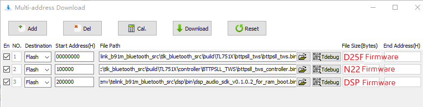
The SDK provides a merge_bin.sh script in multi-core projects, which is used to package the compiled D25F and N22 binary images into a single merged firmware after the build process. The merge_bin.sh script is relatively intelligent: it can automatically detect the controller mode defined by CONTROLLER_MODE, and then merge the corresponding Host and Controller firmware accordingly. As long as both D25F and N22 are successfully built, there is no restriction on the build order.
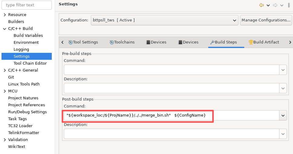
The following file, bttpsll_tws&n22_controller_120.bin, is the merged firmware generated from the BTTPSLL project by combining the D25F and N22 binaries using merge_bin.sh. Users only need to flash this single firmware image at address 0x000000, which is equivalent to programming both D25F and N22 firmware simultaneously.
Since the DSP firmware is not compiled within the SDK, and there is a large address gap between the end address of the N22 and the start address of the DSP, forced merging would reduce flashing efficiency. Therefore, firmware merging is not applied to DSP, and it is still programmed separately.
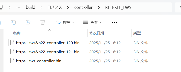
Power Control
Feature Overview
Power control in practice refers to the MCU entering or exiting low-power modes. The low-power modes include three types: suspend mode, deepsleep mode, and deepsleep retention mode. In typical system usage, the power control behavior corresponds to deepsleep mode.
- Deepsleep mode: In this mode, program execution is stopped, and most hardware modules of the MCU are powered down. Only the PM (Power Management) module remains active. Upon wake-up from deepsleep mode, the MCU performs a full restart similar to a power-on reset, and the program reinitializes from the beginning. In deepsleep mode, except for a few registers in the analog domain that can retain state, all SRAM, digital registers, and analog registers are powered off, and lose their contents.
Deepsleep Wake-up Configuration
The MCU low-power wake-up source diagram is shown below. Multiple wake-up sources are available for suspend/deepsleep/deepsleep retention modes. In the SDK, only GPIO_PAD and timer wake-up sources are typically used.
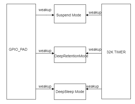
- The PM_WAKEUP_TIMER wake-up source comes from the hardware 32 kHz timer (32 kHz RC timer or 32 kHz crystal timer). The 32 kHz timer is already properly initialized in the SDK. No user configuration is required; it only needs to be enabled in
pm_sleep_wakeup()when selecting this wake-up source. - The PM_WAKEUP_PAD wake-up source comes from the GPIO module. All GPIO pins support wake-up on high/low level, except the four MSPI pins.
In typical power control scenarios, GPIO_PAD is commonly used as the wake-up source. The configuration for GPIO PAD wake-up in deepsleep mode is shown below:
void pm_set_gpio_wakeup(gpio_pin_e pin, pm_gpio_wakeup_level_e pol, int en)
- pin: GPIO number to be configured
- pol: GPIO wake-up polarity.
WAKEUP_LEVEL_HIGHindicates wake-up on a high level, whileWAKEUP_LEVEL_LOWindicates wake-up on a low level
typedef enum
{
    WAKEUP_LEVEL_LOW  = 0,
    WAKEUP_LEVEL_HIGH = 1,
} pm_gpio_wakeup_level_e;
- en: Enables or disables the GPIO wake-up function for the specified pin
Entering and Waking Up from Deep sleep
The API used to configure the MCU to enter sleep mode and handle wake-up is as follows:
int pm_sleep_wakeup(pm_sleep_mode_e sleep_mode, pm_sleep_wakeup_src_e wakeup_src, pm_wakeup_tick_type_e wakeup_tick_type, unsigned int wakeup_tick);
- sleep_mode: MCU sleep mode to be configured.
typedef enum
{
    SUSPEND_MODE   = 0x00,
    DEEPSLEEP_MODE = 0xf0,
    DEEPSLEEP_MODE_RET_SRAM_LOW32K  = 0x01,
    DEEPSLEEP_MODE_RET_SRAM_LOW64K  = 0x03,
    DEEPSLEEP_MODE_RET_SRAM_LOW128K = 0x07,
    DEEPSLEEP_MODE_RET_SRAM_LOW256K = 0x0f,
    DEEPSLEEP_RETENTION_FLAG = 0x0F,
} pm_sleep_mode_e;
- wakeup_src: MCU wake-up source to be configured. Two wake-up sources are supported:
PM_WAKEUP_TIMERandPM_WAKEUP_PAD. Ifwakeup_srcis set to0, the system cannot be woken up after entering sleep mode. - wakeup_tick_type: Wake-up time type of the MCU to be configured.
typedef enum
{
    PM_TICK_STIMER = 0,
    PM_TICK_32K    = 1,
} pm_wakeup_tick_type_e;
- wakeup_tick: Wake-up time of the MCU to be configured.
wakeup_tickis used to determine when the timer will wake up the MCU.
The PM wake-up source type can be obtained via g_pm_status_info.wakeup_src. The wake-up source type has the following values:
typedef enum
{
    FLD_WAKEUP_STATUS_PAD        = BIT(0),
    FLD_WAKEUP_STATUS_CORE       = BIT(1),
    FLD_WAKEUP_STATUS_TIMER      = BIT(2),
    FLD_WAKEUP_STATUS_COMPARATOR = BIT(3),
    FLD_WAKEUP_STATUS_ALL = 0xff,
    FLD_WAKEUP_STATUS_INUSE_ALL = 0x0f,
} pm_wakeup_status_e;
- FLD_WAKEUP_STATUS_TIMER: When this bit is set to 1, it indicates that the current sleep mode is woken up by the Timer.
- FLD_WAKEUP_STATUS_PAD: When this bit is set to 1, it indicates that the current sleep mode is woken up by the GPIO PAD.
- When both FLD_WAKEUP_STATUS_TIMER and FLD_WAKEUP_STATUS_PAD are set to 1, it indicates that both the Timer and GPIO PAD wake-up sources are triggered simultaneously.
PM
The PM module is a core component of the Telink Bluetooth Audio SDK protocol stack. It is responsible for managing system low-power modes, including suspend, deepsleep retention, and WFI (Wait For Interrupt), enabling low-power operation of Bluetooth devices.
Operating Principles
The Telink IC supports three low-power modes:
(1) Suspend mode: In this mode, program execution is halted, similar to a pause state. Most hardware modules of the MCU are powered down, while the PM module remains active. In suspend mode, all IRAM and analog registers retain their state.
(2) Deepsleep mode: In this mode, program execution is stopped, and most hardware modules of the MCU are powered down. Only the PM hardware module remains active. Upon wake-up from deepsleep mode, the MCU performs a full restart similar to a power-on reset, and the program reinitializes from the beginning. In deepsleep mode, except for a few registers in the analog domain that can retain state, all IRAM, digital registers, and analog registers are powered off and their contents are lost.
(3) Deepsleep retention mode: Compared with deepsleep mode, this mode has slightly higher power consumption, as it retains part of the IRAM content. In deepsleep retention mode, most MCU hardware modules are powered down while the PM module remains active. The additional power consumption compared to deepsleep mode is due to the retention IRAM leakage current. Upon wake-up from deepsleep retention mode, the MCU performs a full restart, and the program reinitializes from the beginning.
The SDK supports suspend mode and deepsleep retention mode.
Users can independently invoke deepsleep functionality as needed.
PM Module Features
The PM module provides flexible power management configuration capabilities, including:
- Multiple low-power modes: Supports Suspend, Deepsleep Retention, and Wait For Interrupt (WFI) modes.
- Flexible configuration capability: Provides runtime and compile-time configuration for sleep modes, wake-up sources, and timing parameters.
- Multi-core support: Adapted for multi-core architectures, enabling inter-core synchronization and coordinated sleep mechanisms.
- Callback mechanism: Supports pre-sleep and post-wakeup callbacks to meet user extension requirements.
- Power optimization: Reduces power consumption through task scheduling timing management and wake-up advance control.
PM Module Core Mechanisms
(1) Sleep decision logic
- Pre-check: Checks PM module enable status, whether underlying timing is busy, and whether sleep is allowed.
- Module state check: Evaluates whether BT/LE/TPSLL modules and user tasks are busy.
- Sleep time calculation: Determines the optimal sleep duration by combining user-defined sleep time and protocol stack timing constraints.
(2) Wake-up source management
- Supports timer wake-up, GPIO wake-up, and combined wake-up sources.
(3) Hardware state save and restore
- In sleep modes such as Suspend and Deepsleep Retention, hardware modules may be powered down. The PM module supports saving hardware configuration before sleep and restoring it after wake-up, eliminating the need for reconfiguration and improving system efficiency.
(4) Multi-core architecture support
- Shares sleep information between cores via inter-core communication mechanisms (e.g., shared memory or mailbox).
- The master core aggregates sleep status from all cores and controls system entry into low-power states.
(5) Multi-operation mode support
- Supports both bare-metal and RTOS-based operating modes.
Feature Implementation
(1) PM Module Initialization
PM module initialization includes:
- Registering sleep callback events (can also be performed during system runtime)
- Configuring wake-up sources
- Registering sleep entry and exit callback handlers
- Enabling the PM module
Related API:
- tlksdk_pm_init: Initializes the PM module. The main function is to initialize the internal parameters of the PM module.
/**
 * @brief   for user to initialize low power mode
 * @param   none
 * @return  none
 */
void tlksdk_pm_init(void);
- tlksdk_pm_enableSleep: Enables or disables the PM module. Passing
1enables the PM module, while passing0disables it.
/**
 * @brief   for user to enable low power mode
 * @param   enable - TRUE: enable low power mode ; FALSE: disable low power mode
 * @return  none
 */
void tlksdk_pm_enableSleep(bool enable);
- tlksdk_pm_registerPmEventCallback: Registers a sleep event callback.
/**
 * @brief   Register PM Event callBack
 * @param[in]   e - event number, must use an element of "pm_ev_flag_t"
 * @param[in]   p - callBack function
 * @return  none
 */
void tlksdk_pm_registerPmEventCallback(u8 e, pm_event_callback_t p);
- tlksdk_pm_setWakeupSource: Configures the wake-up source. Supports a combination of timer and GPIO wake-up sources.
/**
 * @brief   for user to set low power mode wake up source
 * @param   wakeup_src - low power mode wake_up source
 * @return  none
 */
void tlksdk_pm_setWakeupSource(pm_sleep_wakeup_src_e wakeup_src);
- tlksdk_pm_getPMWakeupSRC: Gets the current wake-up source.
/**
 * @brief  Function to get the wakeup source of mcu.
 * @param  none
 * @return refer to pm_suspend_wakeup_status_e[for TL721X/TL751X] or pm_wakeup_status_e [for B91\B92].
 */
u32 tlksdk_pm_getPMWakeupSRC(void);
Info:
- B91 refers to the TLSR921x series chips.
- tlksdk_pm_is_enabled: Checks whether the PM module is currently enabled.
/**
 * @brief   Check if the system PM mode is used.
 * @param   none
 * @return  true if system PM mode is used, false otherwise.
 */
bool tlksdk_pm_is_enabled (void);
(2) PM Module Operation
Taking suspend mode as an example, the PM module workflow is as follows:
Step 1: Check whether sleep conditions are met, including whether the PM module is enabled.
Step 2: Pre-sleep check, including whether BT/BLE/TPSLL modules or user tasks are busy. If any module/task is busy, the system does not enter low-power mode.
Step 3: Sleep duration calculation, which combines protocol stack timing constraints and the user-defined expected sleep time to determine the optimal sleep duration.
Step 4: Save hardware configuration.
Step 5: Enter low-power state -> exit low-power state.
Step 6: Restore hardware configuration.
Related APIs:
- tlksdk_pm_enterSleep: Enters the low-power state. Users can call this API where needed and pass the expected sleep duration. The PM module will determine whether to enter low-power mode based on the current system state.
/**
 * @brief   Check the system's readiness and put the CPU into sleep for entering Power Management (PM) mode.
 * @param   sleep_mode : refer to type: pm_sleep_mode_e in driver/pm.h
 * @param   nxt_task_wakeup_tick: Expected wake - up time.
 * @return 16 - bit unsigned int; 0 indicates successful entry into PM mode, non - zero means an issue prevented entry.
 */
u32 tlksdk_pm_enterSleep(u32 sleep_mode, u32 nxt_task_wakeup_tick);
Host Tool Communication
Feature Overview
The current host tool supports both Windows and Linux 64-bit platforms, providing features such as UART OTA and BT/BLE scanning and connection under Dual-Mode Audio Source.
The host tool interface mainly consists of two parts: the serial port selection window and the function window.
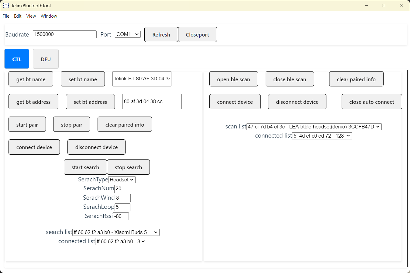
(1) Control Command Interaction
The BT command handler is located in:
tlkapp_host_bt_msg.c -> tlkapp_btmgr_msgHandle
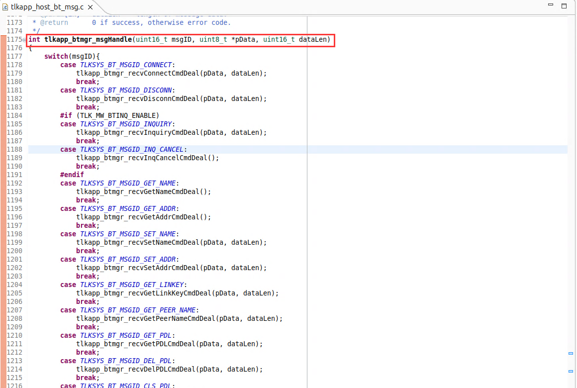
The BLE command handler is located in:
tlkapp_lemgrMsg.c -> tlkapp_lemgr_msgHandle
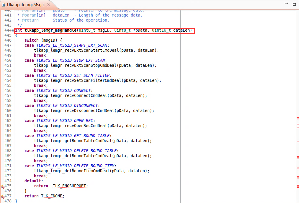
The corresponding command is identified based on msgID, and the associated handler function is then called for processing.
(2) BT Control Commands
-
Get BT Name: Retrieves the BT device name of the development board.
-
Set BT Name: Sets the BT device name of the development board.
-
Get BT Address: Retrieves the BT address of the development board.
-
Set BT Address: Sets the BT address of the development board.
-
Scan BT Devices: Starts the inquiry discovery procedure. Discovered devices will be displayed in the scan list.
-
Cancel BT Scan: Stops the inquiry discovery procedure.
-
Enable BT Pairing: Starts the page procedure for BT pairing.
-
Disable BT Pairing: Cancels the page procedure.
-
Connect BT Device: Connects to the selected device in the scan list. Successfully connected devices will be displayed in the connection list.
(3) BLE Control Commands
-
Enable BLE Scan: Enables BLE scanning. Discovered BLE devices will be displayed in the scan list.
-
Disable BLE Scan: Disables BLE scanning.
-
Connect BLE Device: Connects to the selected device in the scan list. Successfully connected devices will be displayed in the connection list.
-
Disconnect BLE Device: Disconnects the selected device in the connection list.
-
Disable Auto Connection: Disables the automatic connection feature.
(4) UART OTA
The current tool supports UART OTA. Users can select a BIN file and then click start OTA to begin the OTA process.
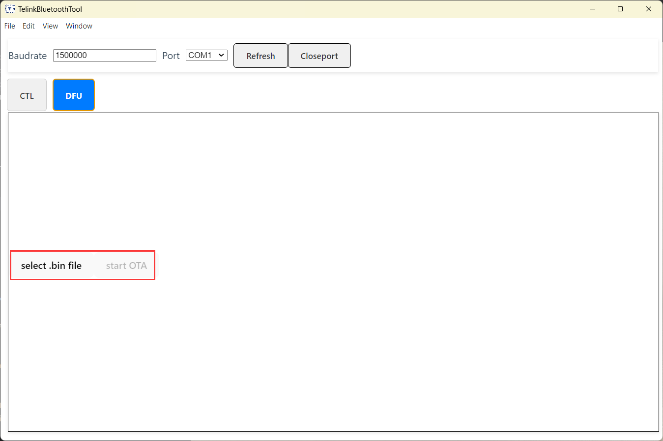
Host Tool Log Viewing (Windows Platform Only)
(1) The log window can be opened through the application status bar.
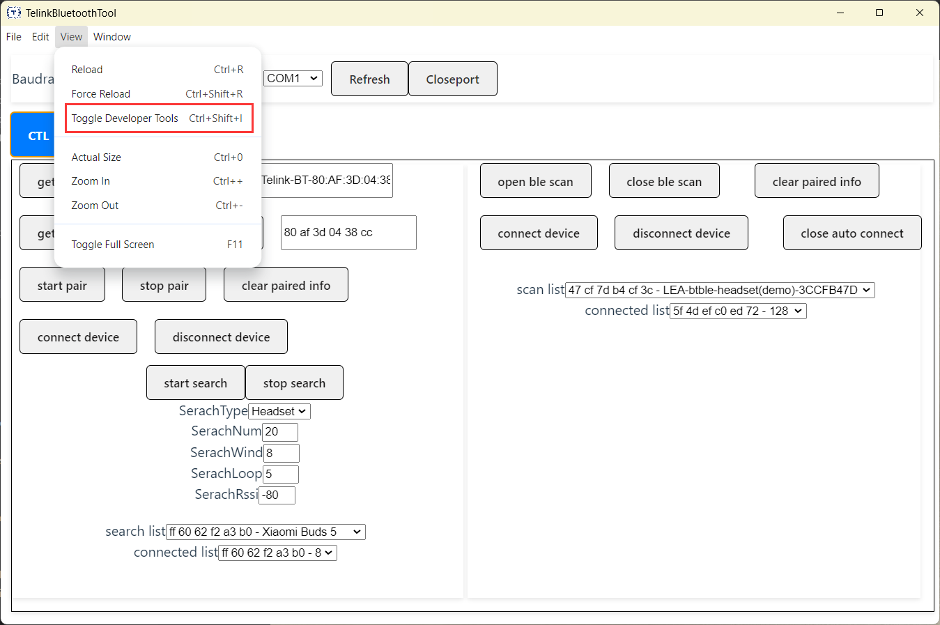
(2) Select the log level to be displayed.
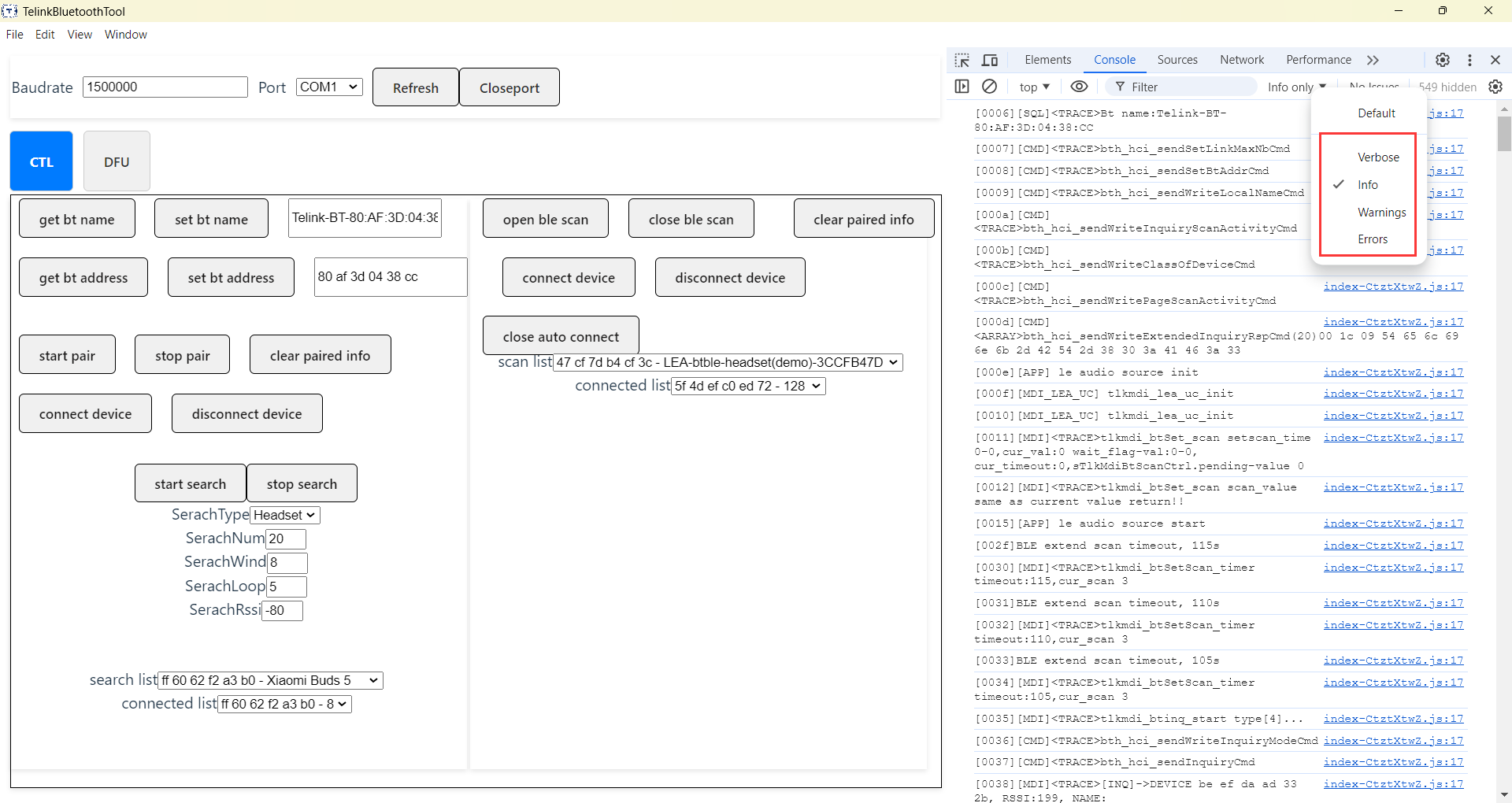
Log levels are divided into four categories:
- Info: Displays log messages output by the development board.
- Verbose: Displays interaction logs between the application and the development board.
- Warning: Displays warnings encountered by the application.
- Error: Displays errors encountered by the application.
Users can select the desired log level and use the filtering function to search for specific log information.
Protocol Overview
The UART protocol uses a custom frame format, which includes a frame header, frame attributes, message payload, and frame tail. Message types mainly include SYSTEM, BT, BLE, Audio, and others. Each message type defines corresponding commands and events.
The current host tool supports partial BT/BLE command transmission and event response handling. For detailed data formats, refer to the BT/BLE Dual-Mode UART Communication Protocol documentation.
User Data Storage
TinySQL is a lightweight embedded database system that provides a structured way to store and manage persistent device data, such as user settings, paired device information, Bluetooth addresses, and more.
Its core concept is to organize different types of data into separate "disks", where each disk is responsible for a specific category of data storage. These disks rely on the underlying tlkapi_save module to implement reliable Flash storage. Users do not need to care about the underlying hardware save implementation and can directly use the get/set interfaces.
The main components of TinySQL include:
- Core module (tlkmdi_tinySql.c): Manages all disk modules and provides unified initialization, save, and restore interfaces.
- Disk modules: Each disk module is responsible for storing a specific type of data.
- User settings disk (tlkmdi_tinySql_disk_userSetting.c)
- BT paired device disk (tlkmdi_tinySql_disk_pairingDevice.c)
- Bluetooth MAC address disk (tlkmdi_tinySql_disk_btMac.c)
- PBAP disk (tlkmdi_tinySql_disk_pbap.c)
- LE disk (tlkmdi_tinySql_disk_le.c)
- Audio disk (tlkmdi_tinySql_disk_audio.c)
The disk index IDs are shown in the following code:
typedef enum
{
    tinySql_notFind = 0XFFFF,     // Indicate that the item was not found
    tinySql_full    = 0XFFFF,     // Indicate that storage is full
    tinySql_nullptr = 0XFFFF,     // Indicate a null pointer

    tinySql_disk0SaveIndex = 0,   // Disk 0 index
    tinySql_disk1SaveIndex,       // Disk 1 index
    tinySql_disk2SaveIndex,       // Disk 2 index
    tinySql_disk3SaveIndex,       // Disk 3 index
    tinySql_disk4SaveIndex,       // Disk 4 index
    tinySql_disk5SaveIndex,       // Disk 5 index
    tinySql_maxSaveIndex,         // Maximum number of save indexes

    tinySql_macSaveIndex            = tinySql_disk0SaveIndex,        // MAC address disk index
    tinySql_userSettingsSaveIndex   = tinySql_disk1SaveIndex,        // User settings disk index
    tinySql_pairingDevicesSaveIndex = tinySql_disk2SaveIndex,        // Paired devices disk index
    tinySql_pbapSaveIndex           = tinySql_disk3SaveIndex,        // PBAP disk index
    tinySql_leSaveIndex             = tinySql_disk4SaveIndex,        // LE disk index
    tinySql_audioSaveIndex          = tinySql_disk5SaveIndex,        // Audio disk index

} TinySql_private_e;
Each disk module must implement the following interface:
typedef struct
{
    void (*init)(void);              // Initialization function
    void (*save)(void);              // Save function
    void (*restoreFactory)(void);    // Factory reset function
} tinySqlDisk_t;
tlkapi_save
The tlkapi_save module is a component used for storing data in Flash memory. It provides a data storage solution based on a dual-sector backup mechanism and offers a certain level of power-loss protection. Its main features are as follows:
- Dual-sector backup mechanism: Uses two Flash sectors for data backup to improve data reliability.
- Checksum verification: Verifies stored data to ensure data integrity.
- Intelligent migration: Automatically migrates valid data to another sector when the current sector runs out of space.
- Version management: Supports data version control to facilitate data compatibility during firmware upgrades.
(1) Workflow
Initialization phase:
- Check the validity of the two sectors.
- Verify data validity based on signatures and version information.
- Locate the latest valid data position.
Save phase:
- Append data to the current sector.
- Include signature, version, and CRC verification information.
Migration phase:
- When the current sector has insufficient space, all valid data is migrated to the other sector.
- The original sector is then erased, and the active operating sector is switched.
Fault-tolerance mechanism:
- In abnormal situations such as unexpected power loss, valid data is recovered by checking signatures, version information, and CRC values.
- Provide multiple retry mechanisms to ensure successful data writing.
(2) Interface Overview
tlkapi_save3_init(): Initializes save control parameters and scans valid data in Flash memory.
int tlkapi_save3_init(tlkapi_save_ctrl_t *pCtrl,
                      uint8_t            sign,
                      uint8_t            version,
                      uint16_t           length,
                      uint32_t           address0,
                      uint32_t           address1);
tlkapi_save3_load(): Loads data from Flash storage.
int tlkapi_save3_load(tlkapi_save_ctrl_t *pCtrl, uint8_t *pBuff, uint16_t buffLen);
tlkapi_save3_smartSave(): Intelligent save function that determines whether to save data directly or perform data migration based on the available storage space.
int tlkapi_save3_smartSave(tlkapi_save_ctrl_t *pCtrl, uint8_t *pData, uint16_t dataLen);
tlkapi_save3_clean(): Clears the save sectors, invalidates the current data, and resets the control parameters.
void tlkapi_save3_clean(tlkapi_save_ctrl_t *pCtrl);
In most cases, users can directly use tlkapi_save3_smartSave(), which internally integrates both tlkapi_save3_save() and tlkapi_save3_migrate().
Asynchronous Storage Mode
As shown in the figure below, TinySQL uses an asynchronous save mechanism by default. This design is mainly based on the following considerations:

- Reduces frequent Flash write operations to extend hardware lifetime, especially in scenarios such as high-frequency volume adjustments within a short period of time.
- Flash memory write operations are significantly slower than RAM accesses. Read/write operations, especially sector erase operations, are time-consuming, and the system often enters critical sections during Flash access. Frequent or long-duration Flash operations may cause certain tasks or contexts to starve.
- The
tlkmdi_tinySql_suspendSaveinterface can be used to temporarily disable Flash read/write operations, protecting critical code sections and preventing conflicts between multi-core XIP instruction fetching and Flash I/O access, which may otherwise lead to bus exceptions or system crashes.
Notes
- Initialization order: Before using any disk-related functionality,
tlkmdi_tinySql_init()must be called for initialization. In this SDK, this interface is already invoked during the system thread initialization stage. - Save timing: Data modifications are not immediately written to Flash. Users need to call
tlkmdi_tinySql_save()manually or wait for the system automatic save mechanism. In this SDK, asynchronous save during system thread idle periods and save-on-power-off mechanisms are used. - Thread safety: The TinySQL module uses mutex locks to ensure thread safety, allowing interface functions to be safely called in multi-threaded environments.
- Memory usage: Since asynchronous saving is used, a certain amount of RAM is occupied as a buffer. Users can reduce memory usage by trimming unnecessary saved content as needed.
Disk Interfaces Introduction
(1) TinySQL Core Interfaces
//This function initializes all registered disk modules.
void tlkmdi_tinySql_init(void);
//Save all pending data to Flash.
int tlkmdi_tinySql_save(void);
// Restore all disk modules to factory settings.
void tlkmdi_tinySql_restoreFactorySettings(void);
//Check whether there are pending save requests.
//true: There are pending save requests.
//false: There are no pending save requests.
bool tlkmdi_tinySql_isRequestSave(void);
//Enable or disable the save function.
//en: 1 indicates the save feature is enabled; 0 indicates it is disabled
//When disabled, save requests will be ignored.
void tlkmdi_tinySql_setSaveEnable(uint8_t en);
//Suspend the save function.
//This function increments the critical section counter to prevent save operations.
void tlkmdi_tinySql_suspendSave(void);
//Resume the save function.
//This function decrements the critical section counter and may trigger save operations when necessary.
void tlkmdi_tinySql_suspendSave(void);
(2) User Settings Disk
The user settings disk is responsible for storing user-specific configurations, such as operating mode, USB mode, key configurations, and Bluetooth device name.
//Set/Get the current operating mode.
uint8_t tlkmdi_tinySql_getWorkMode(void);
void tlkmdi_tinySql_setWorkMode(uint8_t mode);
//Set/Get the USB mode.
uint8_t tlkmdi_tinySql_getUsbMode(void);
void tlkmdi_tinySql_setUsbMode(uint8_t mode);
//Set/Get the USB ID.
uint16_t tlkmdi_tinySql_getUsbID(void);
void tlkmdi_tinySql_setUsbID(uint16_t usbID);
//Set/Get the BT name.
int tlkmdi_tinySql_getBtName(uint8_t *recBuffer);
int tlkmdi_tinySql_setBtName(uint8_t *inBuffer, uint32_t datalen);
//Set/Get the key configuration.
void tlkmdi_tinySql_getKeyCofnig(keyConfigs_t **key_config_info);
void tlkmdi_tinySql_updateKeyCofnig(keyConfigs_t *key_config_info);
(3) BT Paired Device Disk
The BT paired device disk is used to store information about paired Bluetooth devices, including device address, device class, link key, and device name.
//Get the number of paired devices.
uint32_t tlkmdi_tinySql_getPairingDevicesCount(void);

//Clear the paired device list.
void tlkmdi_tinySql_cleanPairingDevices(void);

//Add, delete, update, or query the paired device list.
int tlkmdi_tinySql_updatePairingDevice(uint8_t *pDevAddr, uint32_t *devClass, uint8_t *pLinkKey, uint8_t *pDevName);
int tlkmdi_tinySql_deletePairingDevice(uint8_t *pDevAddr);
int tlkmdi_tinySql_getPairingDeviceByAddr(uint8_t *pDevAddr, uint32_t *devClass, uint8_t *pLinkKey, uint8_t *pDevName);
int tlkmdi_tinySql_getPairingDeviceByIndex(uint32_t index, uint8_t *pDevAddr, uint32_t *devClass, uint8_t *pLinkKey, uint8_t *pDevName);
int tlkmdi_tinySql_getLastPairingDevice(uint8_t *pDevAddr, uint32_t *devClass, uint8_t *pLinkKey, uint8_t *pDevName);
int tlkmdi_tinySql_searchLastPairingDeviceWithMagicWord(uint32_t magicWord, uint8_t *pDevAddr, uint32_t *devClass, uint8_t *pLinkKey, uint8_t *pDevName);
int tlkmdi_tinySql_setPairingDeviceUserMagicWord(uint8_t *pDevAddr, uint32_t magicWord);

//Set/Get the RFC channel ID information of a paired device.
int tlkmdi_tinySql_getPairingDeviceRfcChid(uint8_t *pDevAddr, void *val, uint8_t type);
int tlkmdi_tinySql_setPairingDeviceRfcChid(uint8_t *pDevAddr, uint16_t val, uint8_t type);

//Set/Get the volume of a paired device.
int tlkmdi_tinySql_getPairingDeviceVolume(uint8_t *pDevAddr, uint8_t isMusic, uint8_t *val, uint8_t *isIos);
int tlkmdi_tinySql_setPairingDeviceVolume(uint8_t *pDevAddr, uint8_t isMusic, uint8_t val, uint8_t isIos);
(4) Bluetooth MAC Address Disk
The Bluetooth MAC address disk is used to store the MAC addresses of Bluetooth devices.
//Set/Get the device MAC addresses for Classic Bluetooth, BLE, and Telink 2.4GHz proprietary protocol.
int tlkmdi_tinySql_getBtMacAddress(uint8_t *recBuffer);
int tlkmdi_tinySql_SetBtMacAddress(uint8_t *inBuffer);
int tlkmdi_tinySql_getLeMacAddress(uint8_t *recBuffer);
int tlkmdi_tinySql_setLeMacAddress(uint8_t *inBuffer);
int tlkmdi_tinySql_getTpsAddr(uint8_t *recBuffer);
int tlkmdi_tinySql_getTpdAddr(uint8_t *recBuffer);
(5) PBAP Disk
The PBAP (Phone Book Access Profile) disk is used to store phonebook-related information. The main interfaces are listed below. Users can refer to the comments and tlkmdi_btpbap.c for usage details.
bool tlkmdi_tinySql_getPhoneBookState(void);
int tlkmdi_tinySql_newPhoneBook(uint8_t *btMac);
int tlkmdi_tinySql_addPbapItemBlock(bool isLastOne,uint16_t itemsNum, void *data, uint16_t dataLen);
int tlkmdi_tinySql_getPhoneBookMac(uint8_t * recbuffer);
const uint8_t* tlkmdi_tinySql_getPhoneBookMacPointer(void);
uint16_t tlkmdi_tinySql_getPhoneBookItemNum(void);
const void *tlkmdi_tinySql_searchPhoneBook(tlkMdiTinySqlSearchFunc searchFunc,uint16_t oneItemLen);
RTOS Introduction
The Operating System Abstraction Layer (OSAL) in the SDK is an intermediate layer that provides unified interfaces for applications and protocol stacks. It allows developers to switch between bare-metal and RTOS operating modes. Currently, some projects and chip platforms do not support RTOS due to resource limitations and lack of adaptation.
As shown in the figure below, OSAL adopts the adapter pattern and provides corresponding implementations for each supported operating system environment:
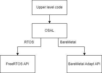
-
BareMetal implementation: Located in the
tlkos_adapt_layer/baremetal/directory, providing simple interface implementations for bare-metal environments. -
FreeRTOS implementation: Located in the
tlkos_adapt_layer/freertos-V5/directory, providing wrapper implementations for FreeRTOS APIs.
The compile-time configuration macro TLK_CFG_RTOS_ENABLE is used to determine which implementation is selected.
The file structure is shown below:
tlklib/os/
├── tlkos.h                    // Main header file
├── tlkos_config.h             // Configuration file
├── tlkos_api/                 // API definition header files
│   ├── tlkos_define.h         // Basic definitions
│   ├── tlkos_kernel.h         // Kernel-related interface
│   ├── tlkos_task.h           // Task management interface
│   ├── tlkos_timer.h          // Timer interface
│   ├── tlkos_semphr.h         // Semaphore interface
│   ├── tlkos_mutex.h          // Mutex interface
│   ├── tlkos_msgq.h           // Message queue interface
│   ├── tlkos_event.h          // Event interface
│   ├── tlkos_memory.h         // Memory management interface
│   └── tlkos_debug.h          // Debug interface
└── tlkos_adapt_layer/         // Specific implementations
    ├── baremetal/             // Bare-metal implementation
    └── freertos-V5/           // FreeRTOS implementation
CFG Configuration Introduction
//Enable or disable RTOS support based on the TLK_CFG_RTOS_ENABLE configuration in app_config.
#if !TLK_CFG_RTOS_ENABLE
#define TLKOS_CFG_BAREMETAL_ENABLE    1
#define TLKOS_CFG_FREERTOS_ENABLE     0
#else
#define TLKOS_CFG_BAREMETAL_ENABLE    0
#define TLKOS_CFG_FREERTOS_ENABLE     1
#endif

//Whether to enable the low RAM resource consumption configuration.
#ifndef TLKOS_CFG_USE_LOWER_RAM_SIZE
#if MCU_CORE_TYPE == MCU_CORE_TL752X
#define TLKOS_CFG_USE_LOWER_RAM_SIZE  1
#else
#define TLKOS_CFG_USE_LOWER_RAM_SIZE  0
#endif
#endif

//Bare-metal memory pool size configuration.
#ifndef TLKOS_CFG_BAREMETAL_HEAP_SIZE
#define TLKOS_CFG_BAREMETAL_HEAP_SIZE (8 * 1024)
#endif

//OS heap size configuration.
#ifndef TLKOS_CFG_OS_HEAP_SIZE
#define TLKOS_CFG_OS_HEAP_SIZE        (30 * 1024)
#endif

//OS tick timer frequency.
#ifndef TLKOS_CFG_HEART_TIMER_TICK_HZ
#define TLKOS_CFG_HEART_TIMER_TICK_HZ (32000UL) //32768(ext_clock) 32000(internal_clock)
#endif

//OS tick frequency.
#ifndef TLKOS_CFG_OS_TICK_HZ
#define TLKOS_CFG_OS_TICK_HZ          (1000)     //1ms
#endif

//PLIC interrupt stack size configuration (in WORDs).
#ifndef TLKOS_CFG_PLIC_STACK_SIZE_WORD
#define TLKOS_CFG_PLIC_STACK_SIZE_WORD    (1024 * 1)
#endif

//OS debug configuration.
#ifndef TLKOS_CFG_DEBUG_ENABLE
#define TLKOS_CFG_DEBUG_ENABLE             (1 && TLK_CFG_RTOS_ENABLE)
#endif

//OS debug log printing.
#ifndef TLKOS_CFG_DEBUG_INFO_OUT
#define TLKOS_CFG_DEBUG_INFO_OUT           ((!TLKOS_CFG_USE_LOWER_RAM_SIZE) && TLKOS_CFG_DEBUG_ENABLE)
#endif

//OS Debug I/O configuration.
#define TLKOS_CFG_DEBUG_IO_ENABLE          (0 && TLKOS_CFG_DEBUG_ENABLE)
//OS stack overflow detection configuration.
#define TLKOS_CFG_DEBUG_STACK_OVERFLOW     (0 && TLKOS_CFG_DEBUG_ENABLE)
//OS malloc failure detection configuration.
#define TLKOS_CFG_DEBUG_MALLOC_FAIL        (1 && TLKOS_CFG_DEBUG_ENABLE)
//OS CPU usage monitoring configuration.
#define TLKOS_CFG_DEBUG_CPU_USAGE          (0 && TLKOS_CFG_DEBUG_ENABLE)

//OS tickless mode configuration.
#define TLKOS_CFG_TICKLESS_ENABLE     (TLK_CFG_SUSPEND_ENABLE)

#define TLKOS_CFG_CHECK_OS_ENABLE_NUM ((TLKOS_CFG_BAREMETAL_ENABLE) + (TLKOS_CFG_FREERTOS_ENABLE))

#if (TLKOS_CFG_CHECK_OS_ENABLE_NUM) != 1
    #error "TLK_OS_CFG_CHECK_OS_ENABLE_NUM NOT EQUAL TO 1"
#endif

//Configuration for data section and code section allocation.
#define _attribute_os_core_code_ram_sec_ __attribute__((section(".ram_code"))) __attribute__((optimize("O2")))
#define _attribute_os_core_code_flash_sec_ __attribute__((optimize("O2")))

#if MCU_DUAL_CORE_ENABLE
#define _attribute_os_heap_sec_ __attribute__((section(".iram_data")))
#else
#define _attribute_os_heap_sec_
#endif

//Assertion configuration.
#define TLKOS_ASSERT(x)
API Introduction
(1) tlkos_kernel
//Check if an IRQ is currently active
int tlkos_get_irqState(void);
//Get the current kernel state
int tlkos_get_kernelState(void);
//Functions for entering and exiting critical sections
void tlkos_enter_critical(void);
void tlkos_leave_critical(void);
//OS initialization interface
void tlkos_init(void);
//OS startup interface (scheduler startup)
void tlkos_start(TlkOsInitFunc_t initFunc);
(2) tlkos_memory
// Memory allocation/free interface.
void *tlkos_malloc(uint32_t size);
void *tlkos_calloc(uint32_t size);
void tlkos_free(void *ptr);
(3) tlkos_mutex
//Mutex creation interface
int tlkos_mutex_create(TlkOsMutexHandle_t *mutexHandle);
//Mutex destruction interface
int tlkos_mutex_destroy(TlkOsMutexHandle_t mutexHandle);
//Lock and unlock functions
int tlkos_mutex_lock(TlkOsMutexHandle_t mutexHandle);
int tlkos_mutex_unlock(TlkOsMutexHandle_t mutexHandle);
//Interfaces for creating, locking, and unlocking a recursive mutex
int tlkos_recursiveMutex_create(TlkOsMutexHandle_t *recursiveMutexHandle);
int tlkos_recursiveMutex_lock(TlkOsMutexHandle_t recursiveMutexHandle);
int tlkos_recursiveMutex_unlock(TlkOsMutexHandle_t recursiveMutexHandle);
(4) tlkos_semphr
//Binary semaphore creation interface
int tlkos_semphr_createBinary(TlkOsSemphrHandle_t *semphrHandle);
//Counting Semaphore Creation Interface
int tlkos_semphr_createCounting(TlkOsSemphrHandle_t *semphrHandle, uint32_t maxCnt, uint32_t initCnt);
//Semaphore destruction interface
int tlkos_semphr_destroy(TlkOsSemphrHandle_t semphrHandle);
// Semaphore take interface
int tlkos_semphr_take(TlkOsSemphrHandle_t semphrHandle, uint32_t blockTimeMs);
//Semaphore release interface
int tlkos_semphr_give(TlkOsSemphrHandle_t semphrHandle);
//Semaphore release interface in an interrupt service routine
int tlkos_semphr_giveFromISR(TlkOsSemphrHandle_t semphrHandle);
(5) tlkos_task
//Task creation interface; supports dynamic and static creation
int tlkos_task_create(TlkOsTaskEnterCB enterCB, const char *pName, uint32_t stackSize, uint32_t priority, void *CBUsrArg, TlkosTaskExtCfg_t *extArg, TlkOsTaskHandle_t *taskHandle);
//Task destruction interface
void tlkos_task_destroy(TlkOsTaskHandle_t taskHandle);
//Task priority get/set interface
uint32_t tlkos_task_getPriority(TlkOsTaskHandle_t taskHandle);
uint32_t tlkos_task_getPriorityFromIsr(TlkOsTaskHandle_t taskHandle);
void tlkos_task_setPriority(TlkOsTaskHandle_t taskHandle, uint32_t priority);
void tlkos_task_setPriorityFromIsr(TlkOsTaskHandle_t taskHandle, uint32_t priority);
//Task blocking delay interface
int tlkos_task_delayMs(uint32_t delayMs);
// Get the currently running task interface
TlkOsTaskHandle_t tlkos_task_getRunningTask(void);
//Task suspend/resume interface
int tlkos_task_suspend(TlkOsTaskHandle_t taskHandle);
int tlkos_task_resume(TlkOsTaskHandle_t taskHandle);
int tlkos_task_suspendAll(void);
int tlkos_task_resumeAll(void);
//Get the task stack watermark
uint32_t tlkos_task_getStackWaterMark(TlkOsTaskHandle_t taskHandle);
(6) tlkos_timer
//Timer creation interface
int tlkos_timer_create(char *pName, uint32_t periodMs, uint32_t autoReload, TlkOsTimerEnterCB CBEnter, void *pUsrArg, TlkOsTimerHandle_t *timerHandle);
//Timer destruction interface
int tlkos_timer_destroy(TlkOsTimerHandle_t timerHandle);
//Timer start interface
int tlkos_timer_start(TlkOsTimerHandle_t timerHandle);
//Timer reset interface
int tlkos_timer_reset(TlkOsTimerHandle_t timerHandle);
//Timer stop interface
int tlkos_timer_stop(TlkOsTimerHandle_t timerHandle);
//Timer period setting interfaces
int tlkos_timer_setPeriodUs(TlkOsTimerHandle_t timerHandle, uint32_t periodUs);
int tlkos_timer_setPeriod(TlkOsTimerHandle_t timerHandle, uint32_t periodMs);
(7) tlkos_event
// Event table (event flag group) creation interface
int tlkos_event_createTab(uint32_t evtTabLen,TlkOsEventTabHandle_t *evtTabHandle);
//Event table destruction interface
int tlkos_event_destroyTab(TlkOsEventTabHandle_t evtTabHandle);
//Event subscription and callback registration interface
int tlkos_event_regDealCB(TlkOsEventTabHandle_t evtTabHandle,uint32_t index,TlkOsEventDealCB cb);
//Event triggering interfaces
int tlkos_event_set(TlkOsEventTabHandle_t evtTabHandle,uint32_t index);
int tlkos_event_setFromIsr(TlkOsEventTabHandle_t evtTabHandle,uint32_t index);
//Blocking event wait function
int tlkos_event_wait(TlkOsEventTabHandle_t evtTabHandle,uint32_t blockTimeMs);
//Retrieve the event interface
int tlkos_event_get(TlkOsEventTabHandle_t evtTabHandle,uint32_t *evt);
(8) tlkos_msgq
//Message queue creation function
int tlkos_msgq_create(TlkOsMsgQHandle_t *pMsgQHandle, uint32_t msgMaxSize, uint32_t qLength);
//Message queue destruction function
int tlkos_msgq_destroy(TlkOsMsgQHandle_t msgQHandle);
//Message queue send interface
int tlkos_msgq_send(TlkOsMsgQHandle_t msgQHandle, uint8_t *pData, uint32_t dataLen, uint32_t blockTimeMs);
//Blocking message wait function
int tlkos_msgq_wait(TlkOsMsgQHandle_t msgQHandle, uint8_t *pBuff, uint32_t *recLen, uint32_t buffLen, uint32_t blockTimeMs);
Threads Provided in the SDK
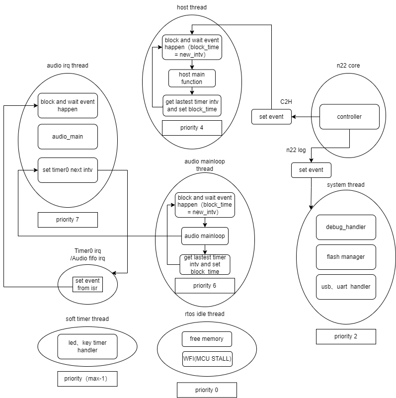
SDK mainly includes the following threads:
-
SYSTEM Task Thread: The fundamental system task responsible for system-level functions, including:
- System power management
- Flash storage management
- USB interface management
- Key and LED device management
- Debug interface management
- Logging system
-
AUDIO Task Thread: Dedicated to audio-related processing, including:
- Audio scheduling management
- UAC (USB Audio Class) device control
- Audio playback and recording control
- DSP-related processing
Note
- The audio task creates sub-threads for decoding.
- HOST Task Thread: Responsible for Bluetooth protocol stack host functions, including:
- HCI layer processing
- Classic Bluetooth protocol support
- BLE protocol support
- TPSLL protocol support
- Priority: TLKSYS_TASK_HOST_PRIORITY(4).
RF Testing (BQB / EMI)
To enter BQB or EMI testing, use the BQB and EMI tools in the BDT software package to download the corresponding firmware, then connect the test instrument to perform the test.
BDT BQB Tool Configuration
Click Tool -> BQB tool to open the tool. In the Test Select, choose BT. Then set the power values under BR Pow and EDR Pow. Click Download to program the firmware into the development board.
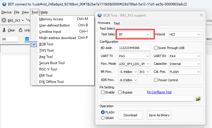
After the download is complete, connect the instrument to start testing.
BDT EMI Tool Configuration
Click Tool -> EMI tool to open the EMI tool. In the Test Select, select BT, then click Download to program the firmware into the development board.
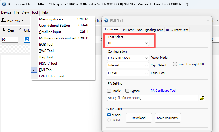
Open the EMI Test interface. Configure either carrier single-tone transmission mode or carrier data continuous transmission mode. Frequency hopping can be enabled or disabled, and the data type can be selected. The parameters include channel and power (enable slice to set the slice value directly). Packet type configuration is also available.
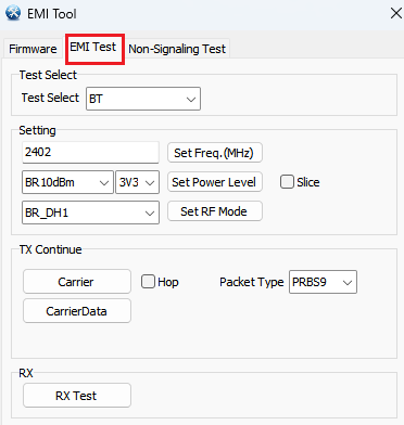
Open the Non-Signaling Test interface. Configure TX burst mode and RX reception mode. In TX burst mode, you can choose to transmit an unlimited number of packets or 1000 packets, and select the data type. In RX mode, you can click RX Count to view the number of received packets and click RSSI to check the received signal strength. The parameters include channel and power (enable slice to set the slice value directly). Packet type configuration is also available.
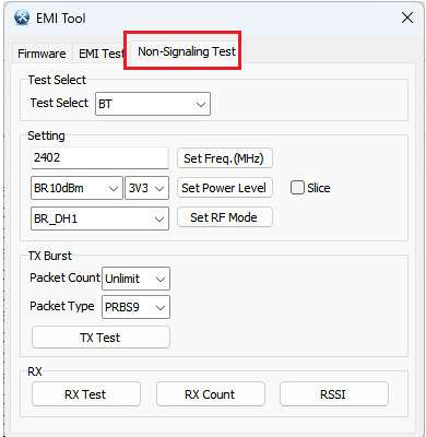
Boot and OTA
The current SDK has implemented a company-standard Bootloader and OTA solution, which is fully compatible with both single-core and multi-core hardware platforms. For implementation details, please refer to the document "Generic Boot and OTA Implementation Solution".
OTA Firmware File Format
The SDK provides a dedicated script for automatic firmware generation. A host tool for firmware generation is planned to be developed in the future to facilitate customer configuration of optional features. The application firmware file format mainly consists of Total FW Descriptors and FW entity. The FW entity further includes Cur FW Descriptor and Cur FW Data. The file structure is shown below:
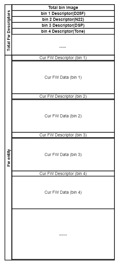
-
Total FW descriptors: 4 KB in size. It provides a global description of all firmware images. By parsing this region, users can obtain information such as the number of firmware images, total firmware size, and supported image combinations.
-
FW entity:
- Cur FW Descriptor: Describes the boot address, VID, PID, version, and other metadata of the current firmware.
- Cur FW Data: The actual firmware data payload.
The firmware parsing format implemented in the SDK is shown below:
typedef struct {
    uint32_t img_version;
    uint32_t img_valid_size;
    uint32_t fw_number;
    uint32_t total_size;
    uint32_t fw_group_number;
    struct sTlk_fw_group_list_t *fw_group_list;
    struct sTlk_fw_descriptors_list_t *fw_descpts_list;   //FW Descripotrs List
    uint8_t recv[16];
    sTlk_cur_fw_entity_crc_t img_crc;
}sTlk_total_fw_descriptors_t;
-
Total FW Descriptorsdata format:- It provides a consolidated description of all firmware images. Both the FW Group List and the FW Descriptors List are stored in a linked-list structure. This design allows the number of firmware images described by each
Total FW Descriptorsentry, as well as the number of file groups, to be variable, making the format extensible.
- It provides a consolidated description of all firmware images. Both the FW Group List and the FW Descriptors List are stored in a linked-list structure. This design allows the number of firmware images described by each
(1) Total FW Descriptors Format
| Type | Size | Description |
|---|---|---|
| Version | Word | Version number of the Total FW Descriptors, used for firmware upgrade compatibility matching. |
| Valid Size | Word | Effective data size of the Total FW Descriptors, used to define the valid boundary of the structure. |
| FW Count | Word | Number of firmware (bin) images recorded in the descriptor. |
| Total Size | Word | Total size of the generated APP firmware image, used to determine whether dual-bank (ping-pong) upgrade is supported. |
| FW Group Count | Word | Number of firmware groups (minimum 1). Multiple firmware groups are supported for multi-bin systems. |
| FW Group List | Array | Linked list of firmware groups. The number of nodes is determined by FW Group Count. The node format is defined in the table below. |
| FW Descriptors List | Array | Linked list of individual firmware descriptors. The number of nodes is determined by FW Count. Each node has a fixed length (see table below). |
| Resv | Array | 16-byte reserved field for future extensions. |
| CRC | Array | 32-byte checksum of the Total FW Descriptors. It must be verified during Boot or OTA upgrade to ensure integrity and validity of the descriptor. |
-
FW Group Listdata format:-
The
FW Group Listis implemented as a linked list. Each node represents one firmware group, and the number of nodes corresponds to the number of firmware groups. It is used for application switching. -
Each firmware group contains a Bin Count, which indicates the number of firmware images within the group. The combination of Bin Type and Bin Version is used to identify and locate a specific firmware image. The number of such combinations depends on the value of Bin Count.
-
To support both single-core and multi-core architectures, the SDK introduces the concept of a firmware group. Multi-bin switching is therefore implemented as firmware group switching. Together with the Fw Setting in the Boot and OTA Configuration Zone, the system can determine which firmware group should be selected.
-
To ensure compatibility across single-core and multi-core chips, the number of firmware images per group is not fixed. For example, in single-core chips, each group contains only one firmware image, while in multi-core chips, each group contains at least one image, with an upper limit depending on the chip type (e.g., up to 3 for TL751x series chips).
-
By using Bin Type and Bin Version, the system can traverse the FW Descriptors List in
Total FW Descriptorsand locate a unique firmware image.
-
(2) FW Group List Format
| Type | Size | Description |
|---|---|---|
| Bin Count | Word | Indicates the number of firmware (bin) images contained in the current firmware group, defining the boundary of the group. |
| Bin Type | Word | Firmware type identifier, supporting custom parsing. Standard values (e.g., 01 = MCU, 02 = N22, etc.); FF indicates an invalid type. |
| Bin Version | Word | Firmware version number. Together with Bin Type, it uniquely identifies the storage location of the corresponding firmware. |
| resv | Word | Reserved field for future extensions. |
-
FW Descriptors Listdata format:This structure contains information for a specific firmware image.
Note that
Bin Startonly records the offset of the corresponding firmware within the packaged firmware generated by the build script. It does not represent the actual execution (boot) address.After the OTA receives the complete
OTA APP FWimage, it must parse theBin Startfield to locate the corresponding firmware. It then retrieves the boot address from theCur FW Descriptorand copies the firmware to the actual execution address for runtime operation.
(3) FW Descriptors List
| Type | Size | Description |
|---|---|---|
| Bin Type | Word | Byte0: Current bin type, supporting customer-defined parsing. Standard values include 01–MCU, 02–N22, 03–DSP, 04–BOOTLOADER, etc. Values ≥ 0x0F are reserved for customer-specific usage (Boot does not perform relocation). Byte1: Boot type: 01–Flash boot, 02–RRAM boot, 03–RAM boot, 04–direct jump execution, 0F–customer-defined. The Bootloader parses this field to determine the target execution location. Byte2–Byte3: Reserved. |
| Bin Version | Word | Version of the current bin. Together with Bin Type, it uniquely identifies a specific firmware image. |
| Bin Start | Word | Offset address of the current bin within the packaged firmware image. |
| Bin Size | Word | Size of Cur FW Descriptor + Cur FW Data + Total CRC. |
| resv | Array | 16-byte reserved field. |
Cur FW Descriptordata format: It contains the header information of the firmware.
Cur FW Descriptor (Aligned to 4 bytes):
| Type | Size | Description |
|---|---|---|
| PID | Word | Typically skipped when all bits are F. Used to identify Product ID under special conditions and is not parsed in normal cases. |
| VID | Word | Typically skipped when all bits are F. Used to identify Vendor ID under special conditions and is not parsed in normal cases. |
| Boot Address | Word | Actual firmware execution address (Flash address). Used by the Bootloader as the entry point for execution. |
| Feature Map | Array (8 Bytes) | Feature set of the firmware, including compression/decompression, encryption/decryption, checksum, and integrity verification capabilities. These features are optionally configurable by the customer, and some are still under development. |
| Resv | Array (12 Bytes) | Reserved field for future extension. |
| CRC | Array (32 Bytes) | CRC checksum of the Cur FW Descriptor, used to verify integrity and validity of the descriptor itself. |
Cur FW Datadata format: It contains the actual firmware binary data.
Cur FW Data (Aligned to 4 bytes):
| Type | Size | Description |
|---|---|---|
| Payload | Array | The actual firmware binary data (content of the bin file), which serves as the functional payload of the firmware. |
| CRC | Array (32 Bytes) | CRC checksum covering both Cur FW Descriptor + Payload, used to ensure overall integrity of the firmware image and descriptor. |
Boot Introduction
During the Boot stage, the boot_loader first checks whether the system enters UART DFU mode. If UART DFU mode is entered, firmware can be upgraded via UART. In this mode, the boot_loader directly erases the firmware in Region A and downloads the new firmware into Region A. After DFU succeeds, the system immediately reboots.
If UART DFU mode is not entered, the system then checks whether it enters Minimal System mode for wireless OTA. Otherwise, it checks whether a new firmware image exists in backup Region B.
- If a valid new firmware exists in Region B and passes verification, it is moved to Region A, and the system reboots.
- If the firmware in Region B is invalid, the system continues to check relevant parameters in Region A and then jumps to the application execution region.
Before executing the application, the system first validates whether the Total FW Descriptors section is valid. If this section is invalid, the system defaults to UART DFU mode and waits for a firmware update. It then proceeds to verify the integrity of each firmware component.
After the boot_loader successfully loads the application:
- Single-core system: The system directly enters APP execution.
- Multi-core system: After the main core starts running, it actively loads and transfers the firmware for the secondary core to bring it into operation.
The boot_loader startup flow is as follows:
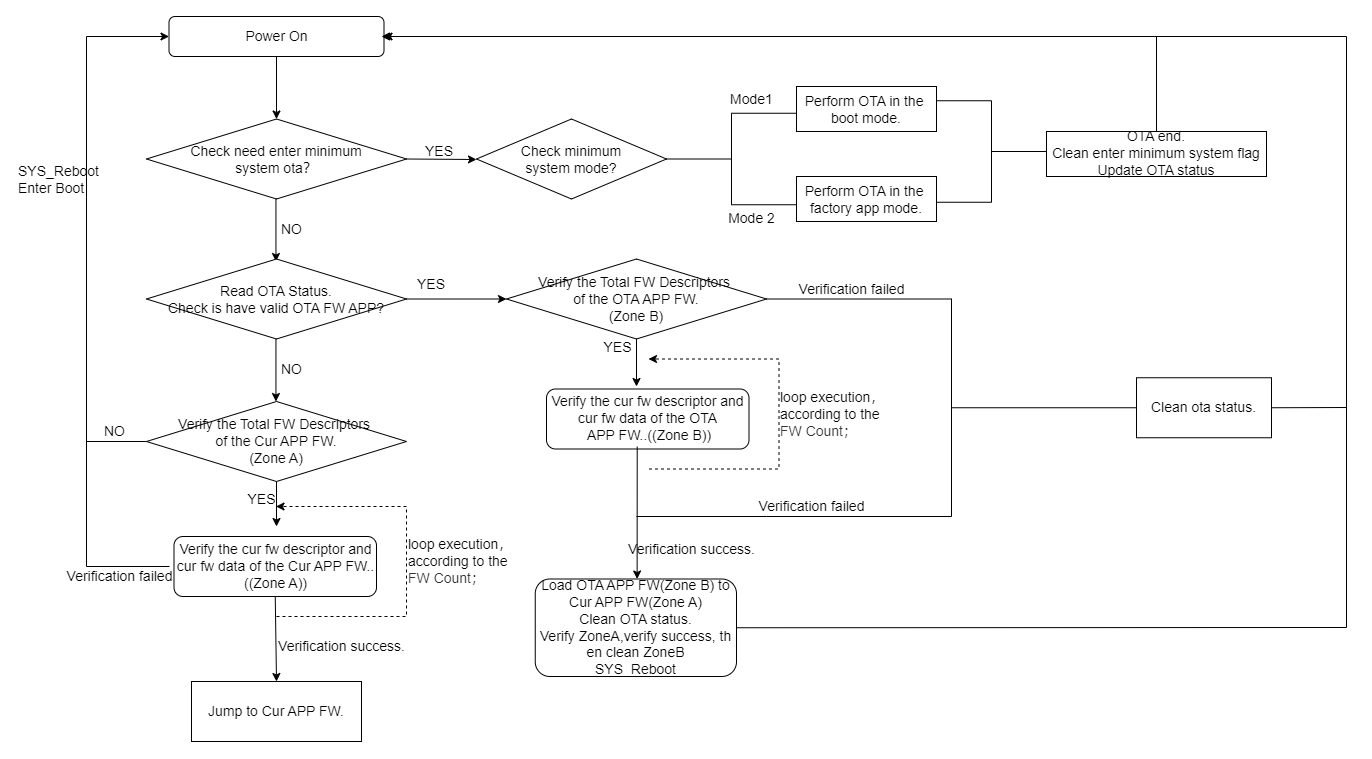
The multi-core startup flow of the boot_loader is as follows:
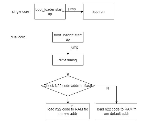
During normal APP execution, on a multi-core chip, the main core uses the following two functions to locate the secondary core firmware in Flash and then copies it to the corresponding RAM location.
uint32_t tlkmw_getN22StartUpAddrFromFlash(void)
{
    return tlkmw_getBinStartUpAddrFromFlash(BINX_N22);
}

uint32_t tlkmw_getDSPStartUpAddrFromFlash(void)
{
    return tlkmw_getBinStartUpAddrFromFlash(BINX_DSP);
}
OTA Transmission
The OTA data transmission flow is as follows:
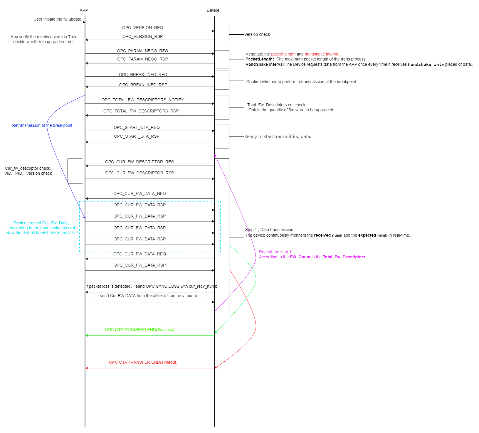
OTA Usage
To use the OTA feature, it must be enabled by defining the corresponding macro.
The system must be booted using the boot_loader when OTA is enabled.
#define TLK_MW_USER_CTRL_ENABLE 1
(1) OTA Firmware Generation (Linux)
During OTA operations, a dedicated firmware image is required for OTA usage. Since the OTA firmware contains special metadata, it needs to be converted using specific scripts.
The workflow is as follows:
- Compile the Application to generate the corresponding firmware image, and store it in the specified output directory.
- Execute the script file
firmware_generation.shand follow the prompts to select the corresponding options.
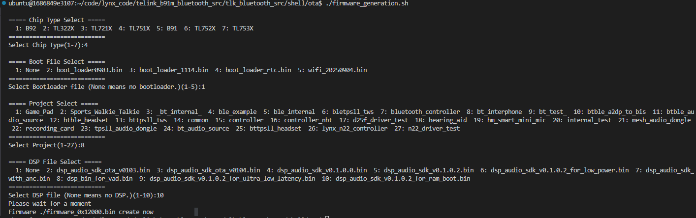
(2) OTA Firmware Generation (Windows)
The script is developed based on Python 3.7 or later. Developers must first complete the configuration of a Python 3.7+ environment. For detailed steps, please refer to the relevant documentation.
- The OTA GUI tool is located at
telink_b91m_bluetooth_src/tlk_bluetooth_src/shell/ota/ota_gui.pyand requires the Tkinter module (natively supported on Windows). - The OTA script is located at
telink_b91m_bluetooth_src/tlk_bluetooth_src/shell/otatlk_ota.py.
Info:
- B91m refers to the TLSR921x, TLSR922x, and TLSR952x series chips.
Script Usage:
Modify the script parameters according to actual requirements. Running the script completes the OTA upgrade process.
If the file does not exist, select "None".
python3 tlk_ota.py
// or
python tlk_ota.py
d25f_bin = tlk_bin_file_info("ota/bt_interphone.bin", 0x13040, type=0x01)
n22_bin = tlk_bin_file_info("ota/bt_interphone_controller.bin", 0x50020000, type=2)
dsp_bin = tlk_bin_file_info("ota/dsp_audio_sdk_v0.1.0.2_for_ram_boot.bin", 0x200040, type=3)
OTA GUI Usage:
The script can be packaged into an executable file using Python packaging tools. Please refer to the relevant documentation for detailed methods.
pyinstaller -F -W ota_gui.py
The process can also be completed by running the script each time.
python3 ota_gui.py
// or
python ota_gui.py
The OTA GUI interface is shown below. Users can select D25F, N22, or DSP firmware for upgrade based on the chip type.
- The Address value does not need to be modified by the user. Version indicates the firmware version and is used for system version management. The default value is 1.
- The Boot file is optional. If a Boot file is provided, a Boot + OTA firmware image will be generated, which can be directly flashed starting from address 0x00000000.
- The default output file name is
tlk_ot_file.bin, which can be modified. When Timestamp is enabled, the generated OTA file name will include a timestamp, which helps users perform multi-version debugging. - Click the "Generate OTA" button to generate the OTA file.
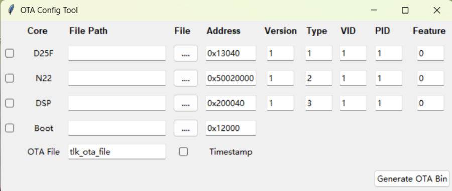
-
As shown in the figure below, when D25F and N22 firmware are selected and the Boot file is enabled, both OTA and OTA + Boot firmware images will be generated.
-
The file names are
tlk_ota_file.binandtlk_ota_file_with_boot.bin.
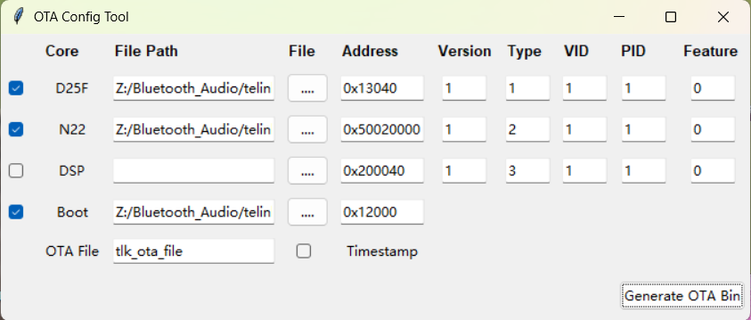
-
If Timestamp is enabled, the generated file name will include a timestamp.
-
The file names:
tlk_ota_file_2025-12-05 14-34-55.bintlk_ota_file_with_boot_2025-12-05 14-34-55.bin.
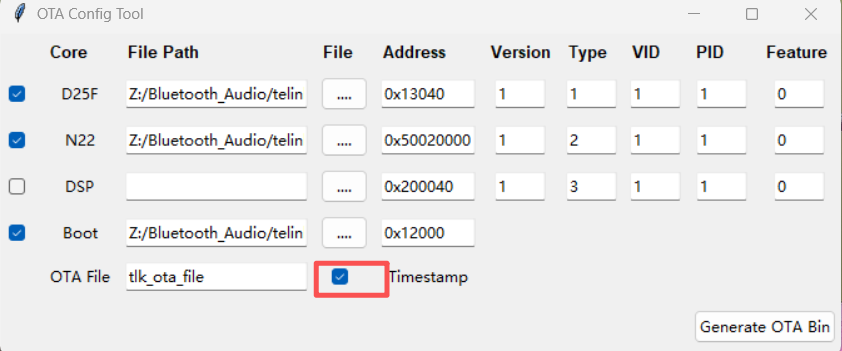
(3) Firmware Download
When using BDT to flash firmware for the first time, the boot_loader must be programmed first, followed by the application firmware (which is generated using a specific conversion script).
- Flash address for
boot_loader:0x00000000(theboot_loaderfile is located in thetelink_b91m_bluetooth_src/boot_loaderdirectory). - Flash address for application firmware:
0x00012000.
Note
- If the boot_loader and application firmware are packaged into a single image using a script, the flash address should be
0x00000000.
(4) APP - BLE Usage
Install the corresponding APP. The OTA firmware can be stored in any directory on the mobile device.
- After installation, open the APP; the interface is shown below:
- Click the refresh button to scan for devices, as shown below:
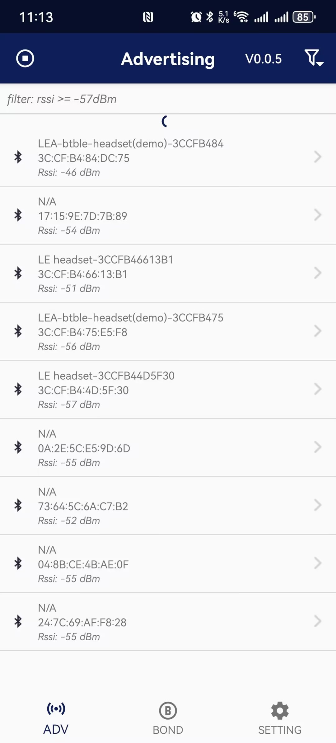
- Select a device to connect, and enter the connection interface.
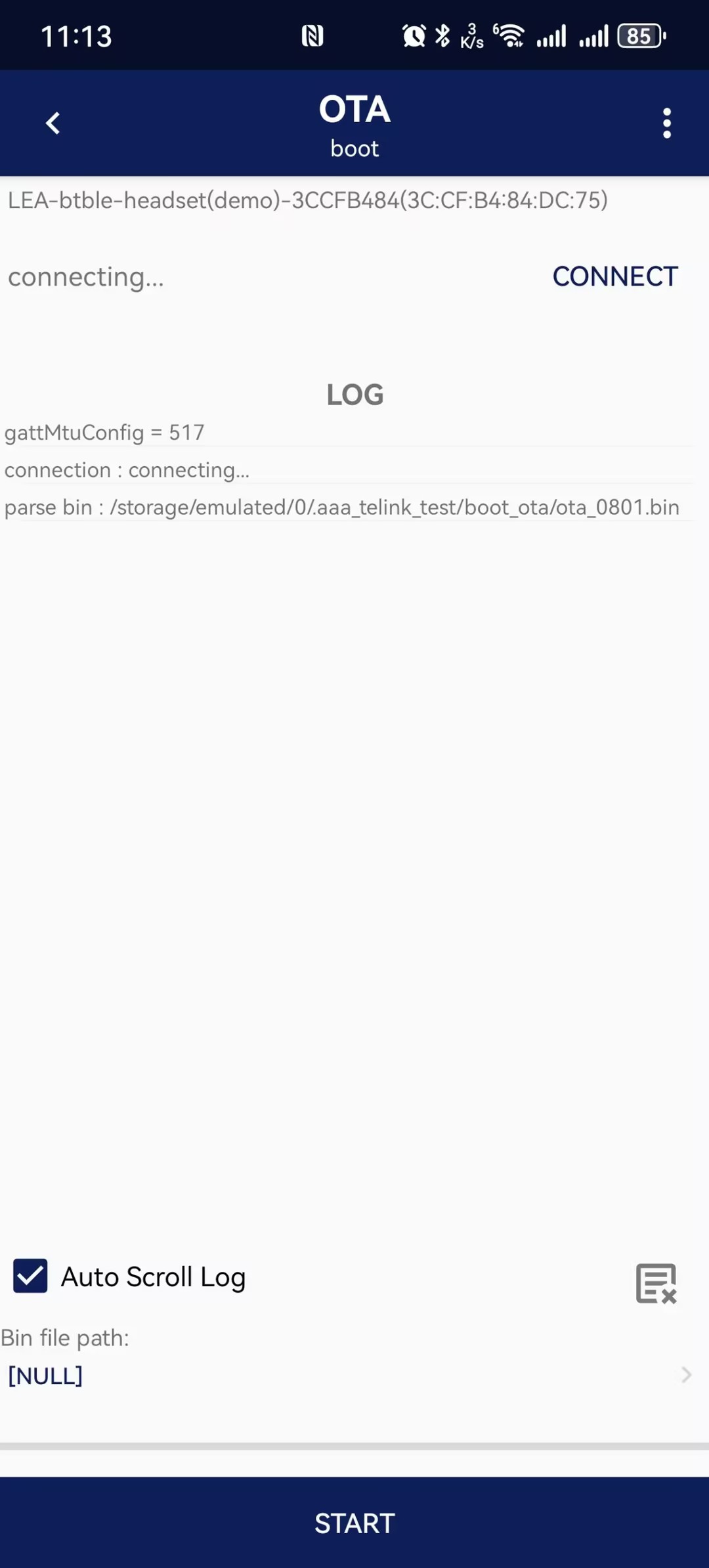
- Click the "CONNECT" button to connect to the device. After a successful connection, "CONNECT" will change to "DISCONNECT".
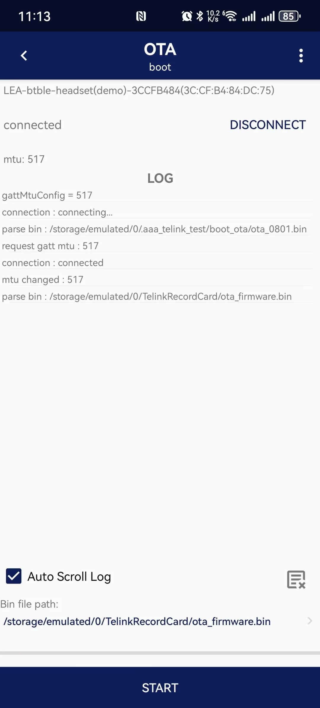
- File import: click "Bin file path" to select the OTA firmware.
- Upgrade: click the "OTA" button to start the upgrade. The progress will be displayed during the update, and the result will be shown upon completion.
(5) APP - UART Usage
- Open the UART upgrade tool and select the correct UART port, then open the serial port:
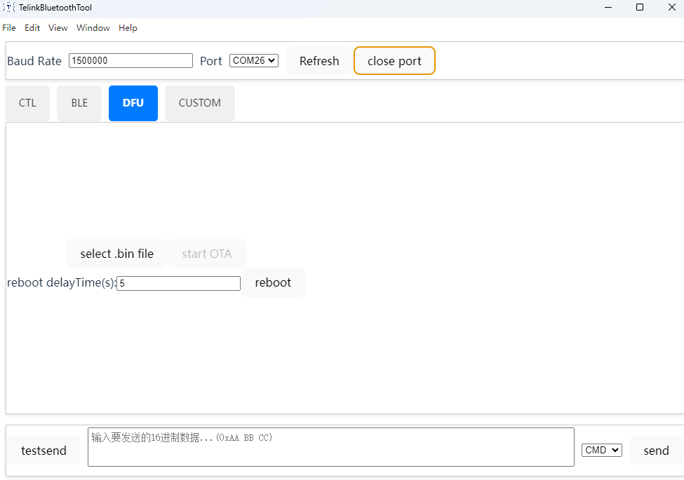
- Click "select bin file" to choose the firmware file.
- Click "start OTA" to begin the upgrade. The progress will be displayed during the update, and the result will be shown upon completion.
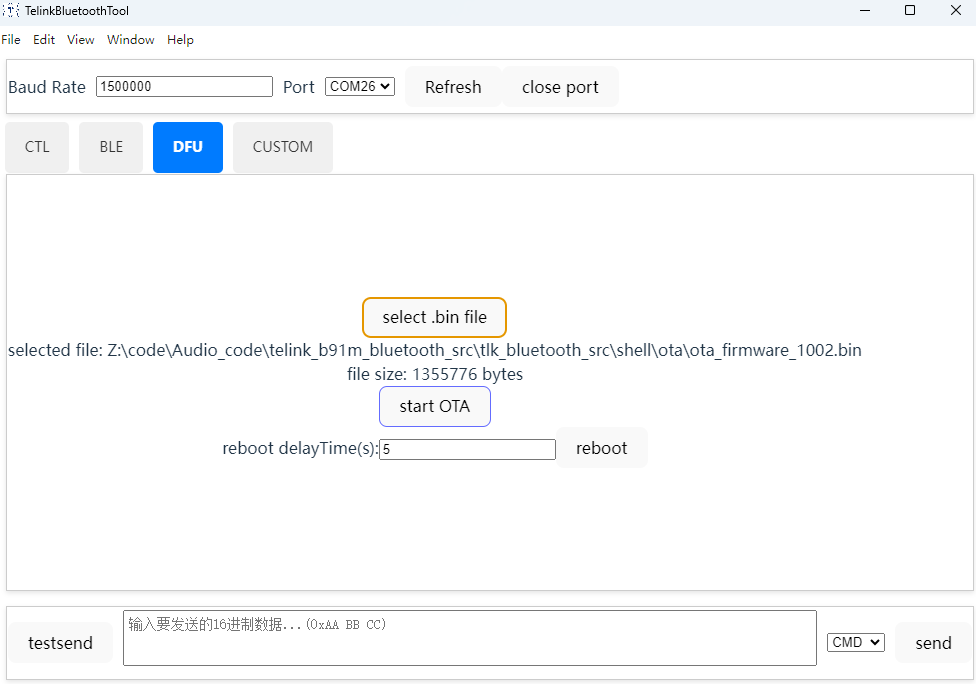
OTA Code Architecture
The OTA feature in the SDK is integrated into the user_ctrl module, which runs in the TLKSYS_TASKID_SYSTEM thread. This module is responsible for handling data and commands from the user application, including OTA updates, volume control, audio parameter configuration, and lighting effect control. It also supports user-defined extensions.
The sTlkMwUsrCtrlTaskList is used to store data from different tasks in a chained structure. All data storage regions are dynamically allocated based on data length. Asynchronous interfaces are also encapsulated to ensure thread safety. The SDK currently supports data from up to 4 tasks.
Note that multiple non-OTA data streams can be processed simultaneously, but only a single OTA data stream is allowed.
The user_ctrl module is disabled by default. To enable it, the TLK_MW_USER_CTRL_ENABLE macro must be enabled.
The system call architecture of the user_ctrl module is shown below:
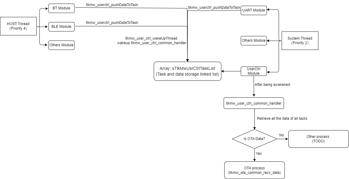
The data structure of the sTlkMwUsrCtrlTaskList, which serves as the core task management array in the user_ctrl module, is as follows:
static sTlkMwUsrCtrlTaskNode_t sTlkMwUsrCtrlTaskList[TLKMW_USER_CTRL_CHN_MAX_NUM]; //TLKMW_USER_CTRL_CHN_MAX_NUM defaults to 4

typedef struct{
    uint32_t taskID;                            //A unique task ID used to identify a specific link. For example, in a Bluetooth dual-connection scenario, the acl_handle is used to distinguish the corresponding device link.
    sTlkMwUsrCtrlBufferNode_t *pBufferHead;     // Head of the linked list
}sTlkMwUsrCtrlTaskNode_t;

typedef struct sTlkMwUsrCtrlBufferNode{
    uint8_t type;                               //Data type: OTA, KEY, LED, etc.
    uint8_t channel;                            //Data channel: UART, BT_SPP, BT_ATT, BLE, etc. (refer to TLKMW_OTA_TRANS_CHN_XXX).
    uint16_t buffer_size;                       //Length of data to be processed by this node
    uint8_t *pBuffer;                           //Data to be processed by this node
    struct sTlkMwUsrCtrlBufferNode *pNext;      //Pointer to the next data item in this task
}sTlkMwUsrCtrlBufferNode_t;
The data dispatch interface can be called from different threads. Internal thread-safety mechanisms are implemented to ensure thread safety.
After the data is submitted, tlkmw_user_ctrl_common_handler will be awakened to process the data. The tlkmw_user_ctrl_common_handler traverses all task nodes and processes all pending data.
The system determines the data type based on the type field in sTlkMwUsrCtrlBufferNode_t and dispatches the data to different processing handlers.
This section focuses on OTA data processing. Processing for other data types should be implemented based on specific application requirements.
int tlkmw_userctrl_pushDataToTask(uint32_t taskID, uint8_t *pData, uint16_t dataLen);
This section focuses on the code structure and usage of the OTA component in the user_ctrl module.
The directory structure of the OTA component is shown below:
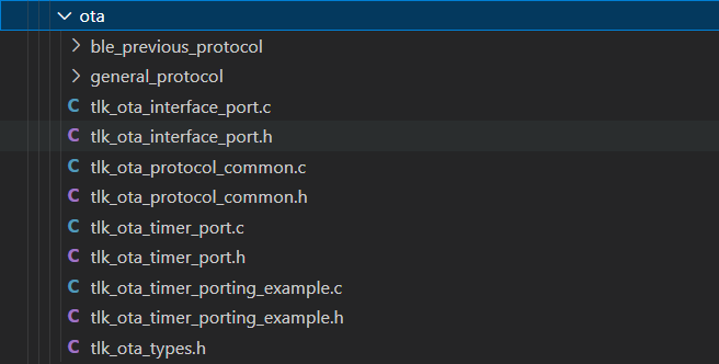
- tlk_ota_types.h: Macro definitions used by the OTA component.
- tlk_ota_timer_port.*: Timer abstraction interfaces used by the OTA module. All interfaces are implemented as weak symbols, allowing users to provide custom implementations.
- tlk_ota_timer_port_example.c: System-level implementation of the OTA timer abstraction interface, tightly coupled with the current SDK.
- tlk_ota_interface_port.*: Interface abstraction layer used by the OTA module. All interfaces are implemented as weak symbols, allowing users to provide custom implementations.
- tlk_ota_protocol_common.*: Common interfaces for OTA protocol processing in the current SDK. It encapsulates common interfaces for generic OTA solutions and legacy BLE OTA solutions, including user area storage and TX/RX interface registration.
- ble_previous_protocol/*: Compatibility layer for legacy BLE OTA solutions. Currently not implemented.
- general_protocol/tlk_ota_general_desc_parse.*: Descriptor parsing for the generic OTA protocol.
- general_protocol/tlk_ota_general_protocol_port.*: OTA packet reassembly processing and abstraction interfaces for handling different opcodes. All interfaces are implemented as weak symbols, allowing users to provide custom implementations.
- general_protocol/tlk_ota_general_protocol_port_example.c: Concrete implementation of OTA receive data processing.
(1) Component Initialization
The control parameter structure of the OTA component is shown below:
typedef struct {
    uint8_t optChn;     //Records the current OTA channel. Refer to TLKMW_OTA_TRANS_CHN_XXX.
    uint8_t resv[3];    //Reserved
    uint32_t taskID;    // Records the current OTA task ID. In the current SDK, this field stores the transport handle of wired or wireless devices and is used to distinguish different OTA links in multi-connection scenarios. Users can define this value as needed, but the task ID must be unique.

    sTlkMwUnitIntf_t intf[TLKMW_OTA_TRANS_CHN_MAX]; // Records the TX/RX interfaces corresponding to each channel. All receive interfaces are currently registered to `tlk_ota_general_protocol_recv_data`, and a common parsing flow is used afterward. The transmit interface is registered separately by each OTA link.
    sTlkMwNotifyUnit_t notifyCB[TLKMW_OTA_NOTIFY_ARRAY_NUM];   // Records callback functions used for OTA notifications. During the OTA process, the OTA component invokes the registered callback functions sequentially to notify interested applications of key events and status changes.
}sTlkMwOtaCommon_t;
The OTA component initialization function is defined as follows:
int tlkmw_ota_common_init(void)
{
    /* Initialize internal parameters used by the OTA module */
    OTA_MEMSET(&sTlkMwCommonCtrl, 0, sizeof(sTlkMwOtaCommon_t));
    for (uint8_t i = 0; i < TLKMW_OTA_NOTIFY_ARRAY_NUM; i++) {
        sTlkMwCommonCtrl.notifyCB[i].threadID = 0xFFFF;
    }
    /* Initialize the NVDS interface used by the OTA module */
    tlk_nvds_ota_interface_init(&sTlk_ota_interface);
    /* Store the start address of the SDK local user area, which is used to dynamically calculate the backup region address */
    if (sTlk_ota_interface.nvds_ota_user_load != NULL && sTlk_ota_interface.nvds_ota_user_load((uint8_t*)&sTlk_boot_ota_cfg, sizeof(sTlk_boot_and_ota_cfg_t), NULL) == OTA_NONE) {
        unsigned int address = tlk_nvds_get_full_size() + TLK_CFG_FLASH_PBAP_LIST_ADDR - 0x100000;//The corresponding offset for the last 1M.
        sTlk_boot_ota_cfg.user_area_addr = address;

        tlk_nvds_ota_userarea_addr_save((uint8_t*)&sTlk_boot_ota_cfg, sizeof(sTlk_boot_and_ota_cfg_t), NULL);
    }
    /* Initialize the generic OTA protocol */
    if (tlk_ota_general_protocol_init(&sTlk_ota_interface) != OTA_NONE) {
        return -OTA_INITERR;
    }
    /* Compatibility support for legacy BLE OTA solutions. Currently not implemented. */
    if (tlk_ota_ble_previous_protocol_init(&sTlk_ota_interface) != OTA_NONE) {
        return -OTA_INITERR;
    }

    return OTA_NONE;
}

int tlk_ota_general_protocol_init(nvds_ota_Interface_t *pInterface)
{
    /* Initialize control parameters for the generic OTA protocol */
    OTA_MEMSET(&ota_general_ptotocol_ctrl, 0, sizeof(tlk_ota_general_protocol_t));

    if (pInterface == NULL || pInterface->nvds_ota_malloc == NULL) {
        return -OTA_INITERR;
    }
    /* Initialize the receive buffer used for generic OTA packet reassembly */
    ota_general_ptotocol_ctrl.p_recv_cache_buff = (uint8_t*)pInterface->nvds_ota_malloc(TLKMW_OTA_TRANS_MAX_PACK_SIZE);
    if (ota_general_ptotocol_ctrl.p_recv_cache_buff == NULL) {
        return -OTA_INITERR;
    }

    /* Initialize internal parameters for the generic OTA protocol and load the firmware image information of the current running region into sTlkMwCurImgHeader */
    if (tlk_ota_general_protocol_detail_init(pInterface) != OTA_NONE) {
        return -OTA_INITERR;
    }

/* Register the receive interface for the generic OTA protocol */
    tlkmw_ota_register_chn_recv_interface(TLKMW_OTA_TRANS_CHN_UART, tlk_ota_general_protocol_recv_data);
    tlkmw_ota_register_chn_recv_interface(TLKMW_OTA_TRANS_CHN_BT_SPP, tlk_ota_general_protocol_recv_data);
    tlkmw_ota_register_chn_recv_interface(TLKMW_OTA_TRANS_CHN_BT_ATT, tlk_ota_general_protocol_recv_data);
    tlkmw_ota_register_chn_recv_interface(TLKMW_OTA_TRANS_CHN_BLE_GENERAL_MODE, tlk_ota_general_protocol_recv_data);

    return OTA_NONE;
}
(2) Data Reception Processing
System-Level Data Transmission:
The OTA module in the SDK is a relatively independent component. The application layer is responsible for forwarding the corresponding data to the OTA module, while the module internally performs data parsing and processing.
Currently, the SDK OTA framework supports multi-channel management. Users can implement custom OTA data send/receive interfaces and register them to the corresponding channels to realize customized OTA solutions.
The channel definitions are as follows. Custom channels can also be added as needed:
enum {
    TLKMW_OTA_TRANS_CHN_NONE = 0,
    TLKMW_OTA_TRANS_CHN_UART,
    TLKMW_OTA_TRANS_CHN_BT_SPP,
    TLKMW_OTA_TRANS_CHN_BT_ATT,
    TLKMW_OTA_TRANS_CHN_BLE_GENERAL_MODE,
    TLKMW_OTA_TRANS_CHN_BLE_PREVIOUS_MODE,
    TLKMW_OTA_TRANS_CHN_MAX,
};
The SDK currently supports OTA over four channels: TLKMW_OTA_TRANS_CHN_UART, TLKMW_OTA_TRANS_CHN_BT_SPP, TLKMW_OTA_TRANS_CHN_BT_ATT, and TLKMW_OTA_TRANS_CHN_BLE_GENERAL_MODE. By default, the data reception interfaces for these four channels are centrally managed by the OTA component as follows:
    tlkmw_ota_register_chn_recv_interface(TLKMW_OTA_TRANS_CHN_UART, tlk_ota_general_protocol_recv_data);
    tlkmw_ota_register_chn_recv_interface(TLKMW_OTA_TRANS_CHN_BT_SPP, tlk_ota_general_protocol_recv_data);
    tlkmw_ota_register_chn_recv_interface(TLKMW_OTA_TRANS_CHN_BT_ATT, tlk_ota_general_protocol_recv_data);
    tlkmw_ota_register_chn_recv_interface(TLKMW_OTA_TRANS_CHN_BLE_GENERAL_MODE, tlk_ota_general_protocol_recv_data);


int tlk_ota_general_protocol_recv_data(uint32_t taskID, uint8_t *pData, uint16_t dataLen, void *UserArg)
{
    (void)taskID;
    if (pData == NULL || dataLen < 4) {
        return -OTA_PARAMERR;
    }

    uint16_t offset = 0;
    uint8_t channel = pData[0];
    offset += 1;

/* Channel filtering: prevent OTA data packets from multiple channels from entering OTA processing. */
    if (ota_general_ptotocol_ctrl.channel != 0 && ota_general_ptotocol_ctrl.channel != channel) {
        return -OTA_CHANNELERR;
    }

    ota_general_ptotocol_ctrl.channel = channel;

    offset += 2; //dataLen

    uint8_t opcode = pData[3];
    uint16_t info = 0;

    if (opcode > TLK_OTA_OPC_MAX) {
        return -OTA_PARAMERR;
    }
    offset += 1;

    OTA_ARRAY_TO_UINT16L(pData, offset, info);
    offset += 2;

    uint8_t pack_flag = info & 0x03;
    uint16_t pack_index = (info & 0xFFFC) >> 2;

    if (pack_flag > TLK_OTA_PACK_TYPE_END) {
        OTA_PRINTF("[OTA] pack flag error:%d", pack_flag);
        return -OTA_PARAMERR;
    }

    if (pack_flag == TLK_OTA_PACK_TYPE_COMPLETE) {
        /* No packet assembly is required. Pass directly to the next processing stage to parse the opcode. */
        tlk_ota_general_protocol_deal(ota_general_ptotocol_ctrl.channel, opcode, pData+offset, dataLen-offset, UserArg);
    } else {
        /* Packet assembly is required. */
        if ((dataLen + ota_general_ptotocol_ctrl.recv_cache_len) > TLKMW_OTA_TRANS_MAX_PACK_SIZE) {
            OTA_PRINTF("[OTA] cache buff null");
            return -OTA_PARAMERR;
        }

        if (ota_general_ptotocol_ctrl.recv_cache_opcode != TLK_OTA_OPC_NONE && opcode != ota_general_ptotocol_ctrl.recv_cache_opcode) {
            tlk_ota_general_protocol_clear_recv_cache();
            OTA_PRINTF("[OTA] opcode error:%d, cache:%d", opcode, ota_general_ptotocol_ctrl.recv_cache_opcode);
            return -OTA_PARAMERR;
        }

        if (pack_index != ota_general_ptotocol_ctrl.recv_cache_index) {
            tlk_ota_general_protocol_clear_recv_cache();
            OTA_PRINTF("[OTA] pack index error:%d, cache:%d", pack_index, ota_general_ptotocol_ctrl.recv_cache_index);
            return -OTA_PARAMERR;
        }

        if (pack_flag == TLK_OTA_PACK_TYPE_END) {
            /* Packet assembly is complete. Proceed to the next processing stage to parse the opcode. */
            OTA_MEMCPY(ota_general_ptotocol_ctrl.p_recv_cache_buff + ota_general_ptotocol_ctrl.recv_cache_len, pData+offset, dataLen-offset);
            ota_general_ptotocol_ctrl.recv_cache_len += (dataLen-offset);
            tlk_ota_general_protocol_deal(opcode, opcode, pData+offset, dataLen-offset, UserArg);
            tlk_ota_general_protocol_clear_recv_cache();
        } else {
            ota_general_ptotocol_ctrl.recv_cache_opcode = opcode;
            ota_general_ptotocol_ctrl.recv_cache_index += 1;;
            OTA_MEMCPY(ota_general_ptotocol_ctrl.p_recv_cache_buff + ota_general_ptotocol_ctrl.recv_cache_len, pData+offset, dataLen-offset);

            ota_general_ptotocol_ctrl.recv_cache_len += (dataLen-offset);
        }
    }
    return OTA_NONE;
}
(3) Data Transmission Processing
The data transmission interfaces are registered by the respective modules. If the transmission interface for a channel is not registered, OTA transmission over that channel is not supported. Refer to the following implementation for details:
    tlkmw_ota_register_chn_send_interface(TLKMW_OTA_TRANS_CHN_UART, tlkmdi_comm_sendOTADat);
    tlkmw_ota_register_chn_send_interface(TLKMW_OTA_TRANS_CHN_BT_SPP, tlkmdi_btspp_otaSendData);
    tlkmw_ota_register_chn_send_interface(TLKMW_OTA_TRANS_CHN_BT_ATT, tlkmdi_btatt_otaSendData);
    tlkmw_ota_register_chn_send_interface(TLKMW_OTA_TRANS_CHN_BLE_GENERAL_MODE, blc_svc_tlkOtaV2_sendData);
(4) Protocol Parsing and Processing
The following shows the data structure of the management parameters used for OTA processing within the protocol:
    typedef struct {
        uint8_t curFwNum;           // Firmware currently being transferred
        uint8_t timeout;            // OTA timeout period
        uint8_t status;             // Current OTA status
        uint8_t channel;            // Current OTA transport channel
        uint16_t shakeIntv;         // Handshake interval between the device and host
        uint16_t cache_size;        // Buffered data size for Flash write; write to Flash when it reaches TLKMW_OTA_WRITE_CACHE_SIZE

        uint32_t backAddr;          // Address of the firmware backup area
        uint32_t saveOffset;        // Flash storage offset; add backAddr to obtain the actual address

        uint32_t fwDataStartOffset; // Start offset of the local curFwNum-th firmware within the entire OTA firmware
        uint32_t fwDataTotalSize;   // Total size of the local curFwNum-th firmware
        uint32_t fwDataRecvSize;    // Received size of the local curFwNum-th firmware; used with fwDataTotalSize to determine whether reception is complete
        uint32_t fwDataRecvNumb;    // Data sequence number of the local curFwNum-th firmware already received, used for packet loss detection
        uint32_t fwDataPendNumb;    // Sequence number of the packet to be received after packet loss detection
        uint32_t flash_save_size;   // Size of the buffered data already written to Flash, used to determine whether the entire OTA firmware has been received

        tlk_ota_timer_handle_t timer;   // OTA timer task, used to detect OTA timeout

        uint8_t *p_cache_buffer;    // Buffer for data to be written to Flash; a TLKMW_OTA_WRITE_CACHE_SIZE-byte buffer is automatically allocated with malloc when OTA starts
        nvds_ota_Interface_t *ota_intf; // OTA NVDS interface
    }sTlkMwOta_t;
The interfaces for OTA protocol parsing and processing are provided below. For details on the implementation, refer to the corresponding code. When the start of an OTA update is detected, the interface creates a timer task to monitor for OTA timeout.
void tlk_ota_general_protocol_deal(uint8_t channel,uint8_t opcode, uint8_t *pData, uint16_t dataLen, void *UserArg);
The firmware is stored in Flash by erasing and writing data as it is received. The protocol provides a built-in receive buffer of TLKMW_OTA_WRITE_CACHE_SIZE bytes (4 KB by default). Received firmware data is first written to this buffer. When the amount of buffered data reaches the TLKMW_OTA_WRITE_CACHE_SIZE threshold, the buffered data is written to Flash, and the buffer is cleared.
If the total amount of newly received data and previously buffered data exceeds the write threshold, the portion that meets the threshold is written to Flash first, while the remaining data is temporarily stored in the buffer.
The corresponding implementation interface is provided below:
 static void tlkmw_ota_common_data_cache_deal(uint8_t *pData, uint16_t dataLen, bool isLast)
{
    if (sTlkMwOtaCtrl.p_cache_buffer == NULL || sTlkMwOtaCtrl.ota_intf->nvds_ota_write == NULL) {
        OTA_PRINTF("tlkmw_ota_common_data_cache_deal: cache buffer is NULL");
        return;
    }

    if (sTlkMwOtaCtrl.cache_size + dataLen >= TLKMW_OTA_WRITE_CACHE_SIZE) {
        uint16_t spaceLeft = TLKMW_OTA_WRITE_CACHE_SIZE - sTlkMwOtaCtrl.cache_size;
        uint16_t writeSize = (dataLen > spaceLeft) ? spaceLeft : dataLen;

        OTA_MEMCPY(sTlkMwOtaCtrl.p_cache_buffer + sTlkMwOtaCtrl.cache_size, pData, writeSize);
        sTlkMwOtaCtrl.cache_size += writeSize;

        sTlkMwOtaCtrl.ota_intf->nvds_ota_eraseSector(sTlkMwOtaCtrl.backAddr + sTlkMwOtaCtrl.saveOffset);
        sTlkMwOtaCtrl.ota_intf->nvds_ota_write(sTlkMwOtaCtrl.backAddr + sTlkMwOtaCtrl.saveOffset, sTlkMwOtaCtrl.cache_size, sTlkMwOtaCtrl.p_cache_buffer);
        sTlkMwOtaCtrl.saveOffset += sTlkMwOtaCtrl.cache_size;
        sTlkMwOtaCtrl.flash_save_size += sTlkMwOtaCtrl.cache_size;
        sTlkMwOtaCtrl.cache_size = 0;

        if (dataLen > writeSize) {
            OTA_MEMCPY(sTlkMwOtaCtrl.p_cache_buffer + sTlkMwOtaCtrl.cache_size, pData + writeSize, dataLen - writeSize);
            sTlkMwOtaCtrl.cache_size += (dataLen - writeSize);
        }
    } else {
        OTA_MEMCPY(sTlkMwOtaCtrl.p_cache_buffer + sTlkMwOtaCtrl.cache_size, pData, dataLen);
        sTlkMwOtaCtrl.cache_size += dataLen;
    }

    if (isLast) {
        if (sTlkMwOtaCtrl.cache_size > 0) {
            sTlkMwOtaCtrl.ota_intf->nvds_ota_eraseSector(sTlkMwOtaCtrl.backAddr + sTlkMwOtaCtrl.saveOffset);
            sTlkMwOtaCtrl.ota_intf->nvds_ota_write(sTlkMwOtaCtrl.backAddr + sTlkMwOtaCtrl.saveOffset, sTlkMwOtaCtrl.cache_size, sTlkMwOtaCtrl.p_cache_buffer);
            sTlkMwOtaCtrl.saveOffset += sTlkMwOtaCtrl.cache_size;
            sTlkMwOtaCtrl.flash_save_size += sTlkMwOtaCtrl.cache_size;
            sTlkMwOtaCtrl.cache_size = 0;
        }
    }
}
Audio Path and Algorithms
Audio Scheduler Principles and Implementation
Overall Architecture
The audio scheduler is located in the tlkapp/audio/ directory and consists primarily of the following core modules:
| File | Function |
|---|---|
tlkapp_audioScheduler.c |
Core scheduler implementation |
tlkapp_audioScheduler.h |
Scheduler interface definitions |
tlkapp_audioModinf.c |
Audio module interface management |
tlkapp_audioMsg.c |
Audio message handling |
tlkapp_audioCtrl.c |
Audio playback control |
tlkapp_audio.c |
Main entry point for the audio task |
Task State Machine
The scheduler uses a state machine to manage audio tasks. The states are defined as follows:
typedef enum {
    TLKAPP_AUDIO_SCHEDULER_TASK_STATE_NOINIT = 0,   // noinit
    TLKAPP_AUDIO_SCHEDULER_TASK_STATE_IDLE,         // idle
    TLKAPP_AUDIO_SCHEDULER_TASK_STATE_PAUSED,       // paused
    TLKAPP_AUDIO_SCHEDULER_TASK_STATE_READY,        // ready
    TLKAPP_AUDIO_SCHEDULER_TASK_STATE_RUNNING,      // running(internal)
    TLKAPP_AUDIO_SCHEDULER_TASK_STATE_MUTEX,        // mutex(internal)
    TLKAPP_AUDIO_SCHEDULER_TASK_STATE_CRASH,        // crash(internal)
} TLKAPP_AUDIO_SCHEDULER_TASK_STATE_ENUM;
State Transitions:
| Current State | Operation | Target State | Trigger Condition |
|---|---|---|---|
| NOINIT | Create/Update Task | IDLE/PAUSED/READY | updateTask() is called |
| IDLE | Start | READY | updateTask() is called with state=READY |
| READY | Schedule | RUNNING | The scheduler selects the task |
| RUNNING | Pause | PAUSED/READY | Preempted by a higher-priority task or pauseTask() is called |
| RUNNING | Stop | NOINIT | deleteTask() is called |
| PAUSED | Resume | READY | resumeTask() is called |
| Any | Exception | CRASH | An error occurs during task execution |
Priority System
The scheduler supports eight priority levels (0–7). Higher-priority tasks are scheduled before lower-priority tasks, with higher-priority tasks preempting lower-priority tasks. Tasks with the same priority are scheduled using round-robin scheduling.
Default Priority Levels:
| Audio Type | Priority | Description |
|---|---|---|
TLKAUD_TYPE_TONE |
7 | Highest priority for notification tones |
TLKAUD_TYPE_CC_BT_VOICE |
5 | BT call audio |
TLKAUD_TYPE_BT_VOICE_FORWARD |
6 | BT audio forwarding |
TLKAUD_TYPE_SIDETONE |
4 | Transparency mode |
TLKAUD_TYPE_ANC |
6 | ANC |
TLKAUD_TYPE_CC_BT_MUSIC |
2 | BT music |
TLKAUD_TYPE_A2DP_OUT |
2 | A2DP (Source) output |
TLKAUD_TYPE_LEA_UC_MUSIC |
2 | LE Audio (Client) music |
TLKAUD_TYPE_LEA_US_MUSIC |
2 | LE Audio (Server) music |
TLKAUD_TYPE_INTRTPHONE |
3 | Internal phone use case |
TLKAUD_TYPE_TPH_AUDIO |
1 | TPSLL audio |
TLKAUD_TYPE_UAC_AUD |
1 | UAC audio |
TLKAUD_TYPE_UAC_LOCAL_AUDIO |
1 | UAC local audio |
Task Node Structure
Each audio task is represented by an app_audioScheduler_node_t node:
struct tlkapp_audioScheduler_node_s {
    uint32_t                          taskId;           // taskID = handle + (optype << 16)
    struct tlkapp_audioScheduler_node_s *prev;          // prev node
    struct tlkapp_audioScheduler_node_s *next;          // next node
    struct tlkapp_audioScheduler_node_s *sameDevTask;  // same device task(used for quick switch)
    tlkapp_audioScheduler_taskInfo_t    info;           // task info
    tlkapp_audioScheduler_extraInfo_t   extraInfo;      // extra info(callback etc.)
};
taskInfo Structure:
typedef struct {
    uint8_t optype;     // audio operation type, reference to TLKAUD_TYPE_ENUM
    uint8_t audioType;  // audio type(MUSIC/VOICE), reference to TLKAPP_AUDIO_SCHEDULER_AUDIO_TYPE_ENUM
    uint8_t priority;   // priority, reference to TLKAPP_AUDIO_SCHEDULER_PRIORITY_ENUM
    uint8_t state;       // current state, reference to TLKAPP_AUDIO_SCHEDULER_TASK_STATE_ENUM
} tlkapp_audioScheduler_taskInfo_t;
Core Scheduler Data Structures
typedef struct {
    uint32_t                       busyTimer;           // busy check timer
    uint32_t                       cfg;                 // config flag
    tlkapp_audioScheduler_checkBusyCB checkBusyCB;      // busy check callback
    tlkapp_audioScheduler_node_t  *busyTask;           // current busy task
    tlkapp_audioScheduler_node_t  *runningTask;        // current running task
    tlkapp_audioScheduler_node_t  *readyTaskList[8];   // ready task list by priority
    tlkapp_audioScheduler_node_t  *idleTaskList[8];     // idle task list by priority
    TlkApiTimer_t                  timer;               // scheduler timer
} tlkapp_audioScheduler_t;
Core Scheduling Process
The core scheduling logic is implemented in the tlkapp_audioScheduler_coreSch() function:
Scheduling Algorithm:

1. Traverse priorities from highest to lowest
   for (i = 7; i >= pThreshold; i--)

2. Search the readyTaskList at each priority level
   while (node != NULL)

3. Check whether the task state is READY
   if (node->info.state == TLKAPP_AUDIO_SCHEDULER_TASK_STATE_READY)

4. Perform the busy check
   tlkapp_audioScheduler_switchBusyCheck()
   - If the device is busy, wait for up to 5 seconds before timing out

5. Perform the state transition
   tlkapp_audioScheduler_coreSchCB()
   - Pause the currently running task
   - Start the new task

6. Update task states
   tlkapp_audioScheduler_taskToRunning()
   - Current task: RUNNING → READY (added to readyTaskList)
   - New task: READY → RUNNING
Configuration Flag Descriptions
sameDev is a concept introduced by the audio dongle application. When the Central connects to the same headset, BT calling and BT music represent two different scenarios but use the same device, allowing them to be associated with each other.
This concept is used to refresh the ready-task list. For example, when a dongle call ends, the scheduler can automatically switch to the music task for the same headset.
| Configuration Flag | Description |
|---|---|
CFG_SAME_DEVICE_REFRESH_L2H |
Refresh same-device tasks from lower to higher priority |
CFG_SAME_DEVICE_REFRESH_H2L |
Refresh same-device tasks from higher to lower priority |
CFG_SCH_RESUME_AUTO2READY |
Automatically transition a RESUME task to READY |
CFG_SCH_IDLE_AUTO2RESUME |
Automatically resume an IDLE task |
CFG_IDLE_PREEMPTIVE_RUNNING |
Allow an IDLE task to preempt a RUNNING task |
CFG_NOT_AUTO_START_TASK |
Do not start the task automatically |
CFG_SWITCH_BUSY_CHECK |
Perform a busy check when switching tasks |
Preset Configuration:
// Headset default setting
TLKAPP_AUDIO_SCHEDULER_CFG_SCH_HEADSET_DEFAULT = CFG_SCH_IDLE_AUTO2RESUME | CFG_SWITCH_BUSY_CHECK

// Dongle default setting
TLKAPP_AUDIO_SCHEDULER_CFG_SCH_DONGLE_DEFAULT =
        CFG_SAME_DEVICE_REFRESH_H2L | CFG_SAME_DEVICE_REFRESH_L2H |
        CFG_SCH_IDLE_AUTO2RESUME | CFG_SCH_RESUME_AUTO2READY |
        CFG_IDLE_PREEMPTIVE_RUNNING | CFG_NOT_AUTO_START_TASK

// UAC default setting
TLKAPP_AUDIO_SCHEDULER_CFG_SCH_UAC = CFG_SCH_IDLE_AUTO2RESUME | CFG_NOT_AUTO_START_TASK
Music Playback Flow (BT Music Example)
Complete BT Music Playback Flow
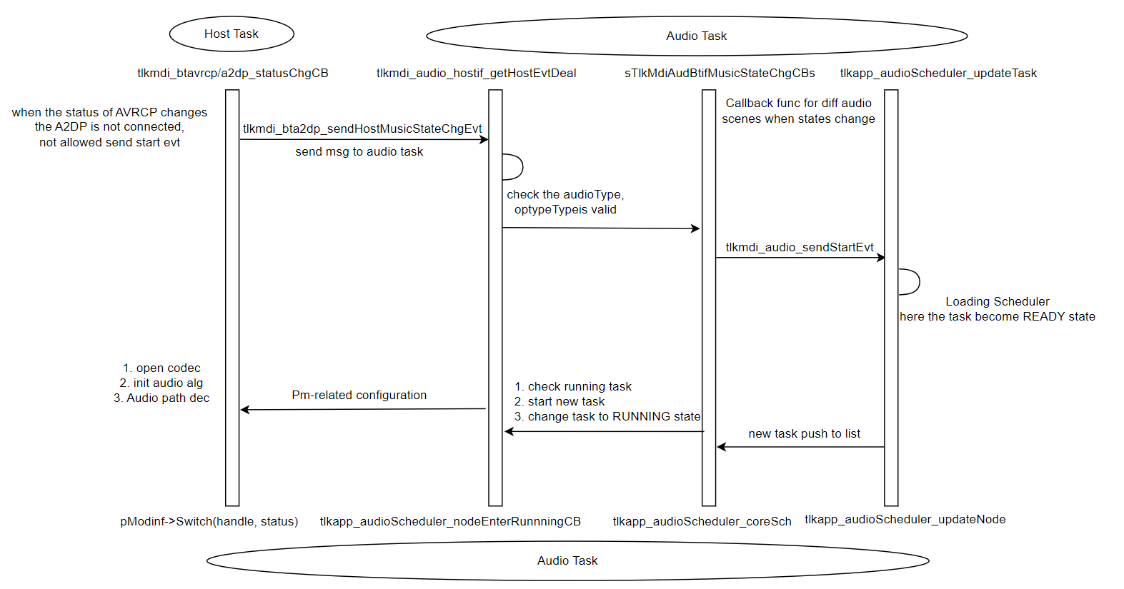
Key Code Paths
(1) State Callback Entry Point (tlkmdi_bt_music.c):
static void tlkmdi_bt_music_state_change_cb(uint16_t handle, uint8_t state)
{
    if (state == TLK_STATE_OPENED) {
        if (!s_tlk_mdi_bt_music_env.enable) {
            tlkmdi_audio_sendStartEvt(TLKAUD_TYPE_CC_BT_MUSIC, handle);
        } else if (btp_a2dpsnk_getStatus(handle) == BTP_A2DP_STATUS_STREAM) {
            tlkmdi_audio_sendStartEvt(TLKAUD_TYPE_CC_BT_MUSIC, handle);
        }
    } else if (state == TLK_STATE_PAUSED || state == TLK_STATE_CLOSED) {
        tlkmdi_audio_sendCloseEvt(TLKAUD_TYPE_CC_BT_MUSIC, handle);
    }
}
(2) Event Message Construction (tlkmdi_audio.c):
int tlkmdi_audio_sendStartEvt(uint8_t audChn, uint16_t handle)
{
    return tlkmdi_audio_sendStartEvtEx(audChn, handle, 0Xff);
}

int tlkmdi_audio_sendStartEvtEx(uint8_t audChn, uint16_t handle, uint8_t priority)
{
    uint8_t buffer[4];
    buffer[0] = audChn;                    // audio channel type
    buffer[1] = priority;                  // priority
    buffer[2] = (handle & 0x00FF);         // handle low byte
    buffer[3] = (handle & 0xFF00) >> 8;    // handle high byte
    return tlksys_sendMsg(TLKSYS_TASKID_AUDIO, TLKSYS_AUD_MSGID_START_EVT, buffer, 4);
}
(3) Task Creation Entry Point (tlkapp_audioMsg.c):
static int tlkapp_audio_startEvtDeal(uint8_t *pData, uint8_t dataLen)
{
    uint8_t optype = pData[0];
    uint16_t handle = ((uint16_t)pData[3] << 8) | pData[2];

    uint8_t audioType = TLKAPP_AUDIO_SCHEDULER_AUDIO_TYPE_MUSIC;
    if (optype == TLKAUD_TYPE_CC_BT_VOICE ||
        optype == TLKAUD_TYPE_LEA_US_VOICE ||
        optype == TLKAUD_TYPE_BT_VOICE_FORWARD) {
        audioType = TLKAPP_AUDIO_SCHEDULER_AUDIO_TYPE_VOICE;
    }

    uint32_t taskID = handle + ((uint32_t)optype << 16);

    if (optype == TLKAUD_TYPE_CC_BT_VOICE &&
        !tlkmdi_audio_btif_allowedCreateScoWithoutHfp(handle)) {
        return tlkapp_audioScheduler_resumeTask(taskID);
    }

    tlkapp_audioScheduler_taskInfo_t info = {
        .audioType = audioType,
        .optype    = optype,
        .priority  = tlkapp_audioScheduler_getDefaultPriority(optype),
        .state     = TLKAPP_AUDIO_SCHEDULER_TASK_STATE_READY,
    };

    return tlkapp_audioScheduler_updateTask(taskID, info, TLKAPP_AUDIO_SCHEDULER_NO_CHANGED);
}
(4) Module Switch Callback (tlkmdi_bt_music.c):
bool tlkmdi_bt_music_switch(uint16_t handle, uint8_t status)
{
    if (status == TLK_STATE_OPENED) {
        g_bt_music_enable_flag = 1;
        s_tlk_mdi_bt_music_env.acl_handle = handle;
        s_tlk_mdi_bt_music_env.enable     = true;
        tlkmdi_btmusic_switch_in(handle);  // enter music mode, config audio path params
    } else {
        g_bt_music_enable_flag = 0;
        s_tlk_mdi_bt_music_env.enable = false;
        bt_music_close_codec();
        tlkmdi_btmusic_switch_out(handle); // exit music mode, release audio path params
    }
    return true;
}
Music Preemption and Resumption Flow
Preemption Scenario
In Bluetooth audio applications, voice calls (Voice) have a higher priority than music playback (Music). When an incoming call is received, or a voice call is initiated, the system automatically preempts the currently playing music, pauses music playback, and starts the voice call.
Priority Comparison:
- BT Music: Priority 2
- BT Voice: Priority 5
Voice Preemption of Music and Music Resumption Flow
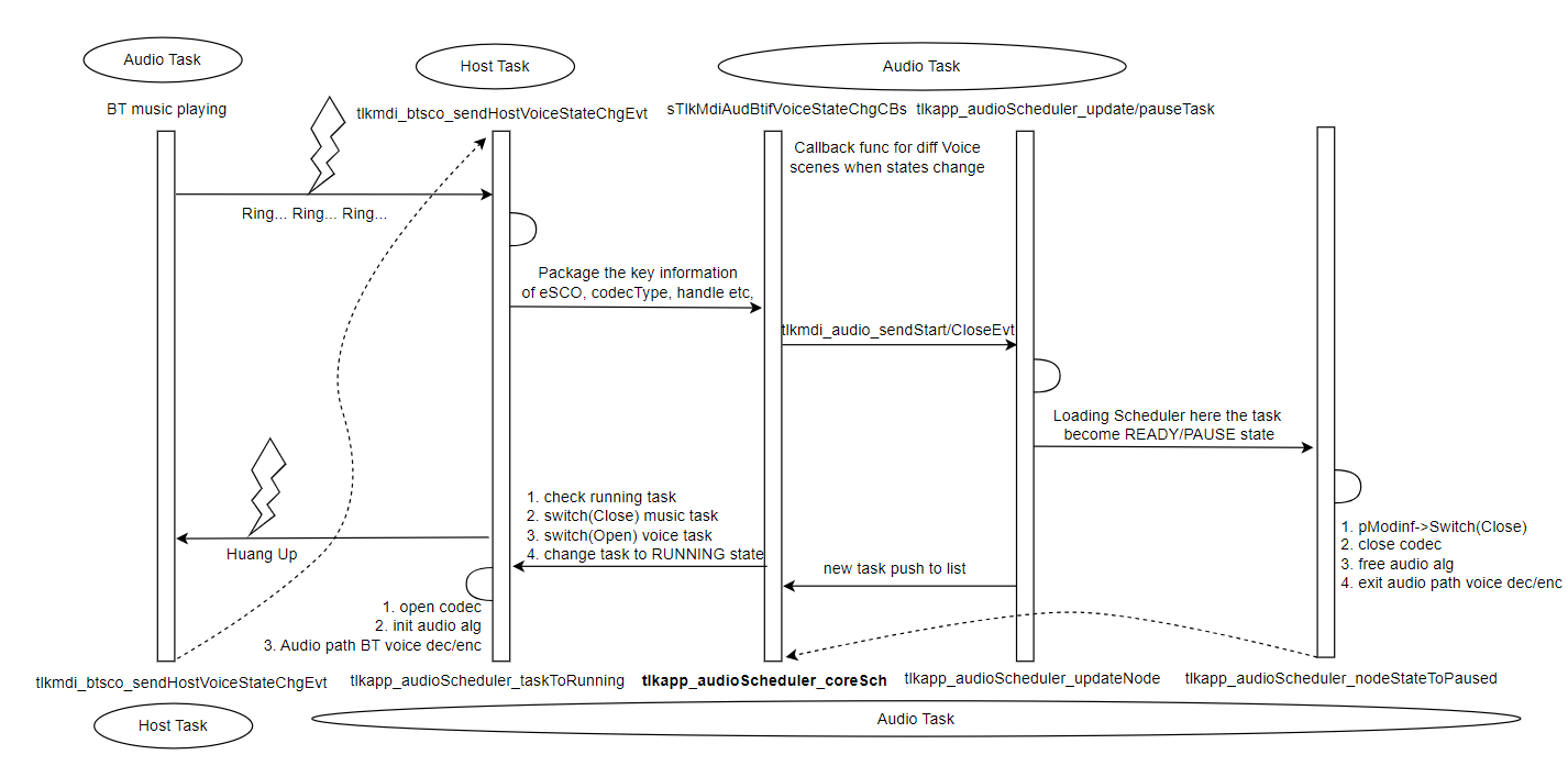
Key Code for Preemption
Core Scheduling and Switching (tlkapp_audioScheduler.c):
static inline bool tlkapp_audioScheduler_coreSchCB(
    tlkapp_audioScheduler_node_t *node,
    bool isAutoOpenNewTask)
{
    tlkapp_audioScheduler_node_t *nowRunningTask = tlkapp_audioScheduler.runningTask;

    // 1. pause current running task
    if (nowRunningTask != NULL) {
        tlkapp_audio_modinfSwitch(
            nowRunningTask->info.optype,
            (uint16_t)nowRunningTask->taskId,
            TLK_STATE_PAUSED);
    }

    if (isAutoOpenNewTask == false) {
        tlkapp_audio_closeHandler();
        return true;
    }

    // 2. start new task
    return tlkapp_audioScheduler_nodeEnterRunnningCB(node);
}
Task State Update (tlkapp_audioScheduler.c):
static inline void tlkapp_audioScheduler_taskToRunning(
    tlkapp_audioScheduler_node_t *node,
    bool isAutoOpenNewTask)
{
    tlkapp_audioScheduler_node_t *nowRunningTask = tlkapp_audioScheduler.runningTask;

    if (isAutoOpenNewTask) {
        // remove from ready list
        tlkapp_audioScheduler_nodeRemoveFromList(node);
        // set as running task
        tlkapp_audioScheduler.runningTask = node;
        tlkapp_audioScheduler_nodeSetNewStateWithChgCB(node,
            TLKAPP_AUDIO_SCHEDULER_TASK_STATE_RUNNING);
    } else {
        // same device task move to front
        tlkapp_audioScheduler_sameDevToFirst(nowRunningTask);
        tlkapp_audioScheduler.runningTask = NULL;
    }

    // original running task set as ready state
    if (nowRunningTask != NULL) {
        tlkapp_audioScheduler_nodeSetNewStateWithChgCB(nowRunningTask,
            TLKAPP_AUDIO_SCHEDULER_TASK_STATE_READY);

        if (nowRunningTask->info.priority != node->info.priority) {
            // different priority, move to front
            tlkapp_audioScheduler_nodePushFrontToList(
                nowRunningTask,
                &tlkapp_audioScheduler.readyTaskList[nowRunningTask->info.priority]);
        } else {
            // same priority, round-robin move to back
            tlkapp_audioScheduler_nodePushBackToList(
                nowRunningTask,
                &tlkapp_audioScheduler.readyTaskList[nowRunningTask->info.priority]);
        }
    }
}
Volume Adjustment
Volume Control Overview
Volume adjustment follows a layered architecture:
(1) Application Layer: Receives user input and calls tlkapp_audio_volumeCtrl().
(2) Scheduler Layer: Dispatches volume operations to the active audio task or a paused task.
(3) Module Layer: Each audio module implements the corresponding volume operation, such as through the AVRCP protocol.
Volume Control Process
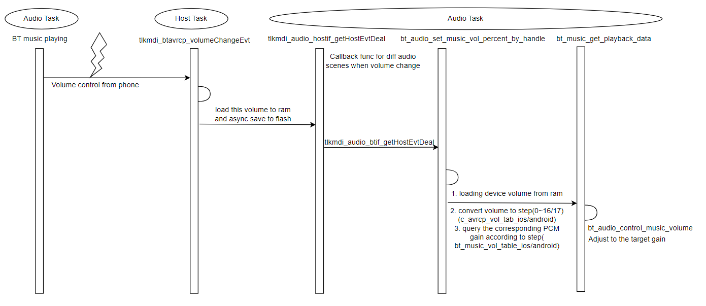
Key Code
Volume Control Entry Point (tlkapp_audioCtrl.c):
int tlkapp_audio_volumeCtrl(uint8_t isInc)
{
    uint8_t volType;
    if (isInc) {
        volType = TLKAUD_OPCODE_VOLUME_INC;
    } else {
        volType = TLKAUD_OPCODE_VOLUME_DEC;
    }

    // operate current running task first
    const tlkapp_audioScheduler_node_t *nowTask =
        tlkapp_audioScheduler_getRunningTask();
    if (nowTask != NULL) {
        bool ret = tlkapp_audio_modinfOperate(
            (uint16_t)nowTask->taskId,
            nowTask->info.optype,
            &volType, 1);
        return ret ? TLK_ENONE : -TLK_EFAIL;
    }

    // if no running task, find paused music task
    const tlkapp_audioScheduler_node_t *taskNode =
        tlkapp_audioScheduler_SchPausedTask(
            false,
            TLKAPP_AUDIO_SCHEDULER_AUDIO_TYPE_MUSIC);
    if (taskNode == NULL) {
        return -TLK_ENOOBJECT;
    }

    uint8_t optype = taskNode->info.optype;
    bool res = tlkapp_audio_modinfOperate(
        (uint16_t)taskNode->taskId,
        optype,
        &volType, 1);
    return res ? TLK_ENONE : -TLK_EFAIL;
}
BT Music Volume Handling (tlkmdi_bt_music.c):
bool tlkmdi_bt_music_operate(uint16_t handle, uint8_t opcode, uint8_t *pdata, uint16_t dataLen)
{
    (void)pdata;
    (void)dataLen;

    switch (opcode) {
    case TLKAUD_OPCODE_VOLUME_INC:
    {
        // increase volume
        tlkmdi_audio_btif_VolumeOperate(handle, true, true);
    } break;
    case TLKAUD_OPCODE_VOLUME_DEC:
    {
        // decrease volume
        tlkmdi_audio_btif_VolumeOperate(handle, false, true);
    } break;
    // ... other operation codes
    default:
        return false;
    }
    return true;
}
Volume Adjustment Considerations
(1) Prioritize the Running Task: Volume adjustments are applied to the currently playing task first.
(2) Paused Tasks Can Be Adjusted: When no task is running, the volume setting of a paused task can be adjusted.
(3) Protocol Synchronization: Volume changes are synchronized with the mobile device through the AVRCP/HFP protocols.
(4) Local Storage: The volume level is typically stored in Flash and restored when the device is powered on again.
Add a Custom Audio Scenario
Overview
Adding a custom audio scenario requires the following additions and modifications:
- Add the
.cimplementation file for the new audio scenario. - Add the
.hheader file for the corresponding interface declarations. - Add the new audio type to the
TLKAUD_TYPE_ENUMenumeration. - Set the default priority for the new audio scenario.
- Register the audio module in the
spTlkAppAudioModinfsstructure. - Include the required header files.
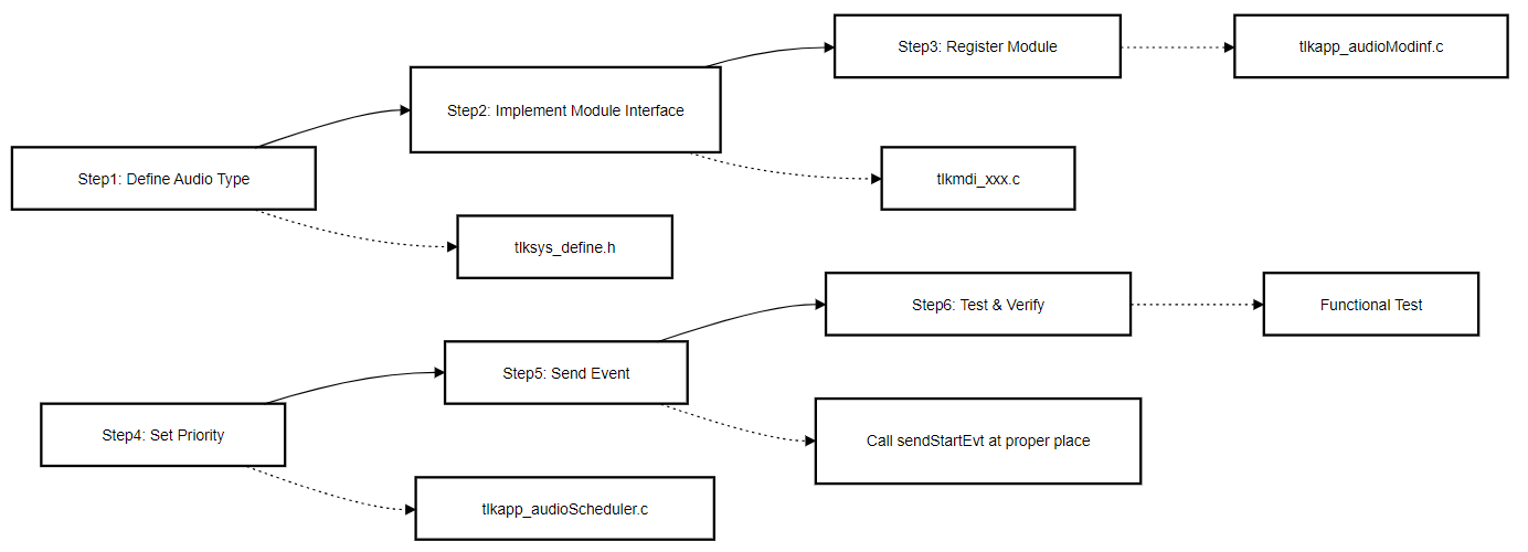
Step 1: Define the Audio Type
Add the new audio type to the TLKAUD_TYPE_ENUM enumeration in tlksys_define.h:
typedef enum
{
    TLKAUD_TYPE_TONE = 0,
    TLKAUD_TYPE_CC_BT_VOICE,
    TLKAUD_TYPE_CC_BT_MUSIC,
    // ... current supported types

    // add custom audio types
    TLKAUD_TYPE_CUSTOM_AUDIO,      // custom audio scene 1
    TLKAUD_TYPE_CUSTOM_AUDIO2,      // second custom audio scene (optional)

    TLKAUD_TYPE_MAX,
} TLKAUD_TYPE_ENUM;
Step 2: Implement the Module Interface
Create a new module implementation file named tlkmdi_custom_audio.c:
/**********************************************************************
 * @file    tlkmdi_custom_audio.c
 * @brief   custom audio module implementation
 **********************************************************************/

#include "tl_common.h"
#include "tlkapi/tlkapi.h"
#include "tlkmw/tlkmw.h"

// module environment variables
static struct {
    uint8_t  enable;
    uint16_t handle;
} s_tlk_mdi_custom_audio_env = {0};

/**
 * @brief   initialize custom audio module
 */
static int tlkmdi_custom_audio_init(void)
{
    tmemset(&s_tlk_mdi_custom_audio_env, 0, sizeof(s_tlk_mdi_custom_audio_env));
    return TLK_ENONE;
}

/**
 * @brief   switch custom audio module state
 * @param   handle - connection handle
 * @param   status - TLK_STATE_OPENED/TLK_STATE_CLOSED
 * @return  true-success, false-fail
 */
static bool tlkmdi_custom_audio_switch(uint16_t handle, uint8_t status)
{
    if (status == TLK_STATE_OPENED) {
        s_tlk_mdi_custom_audio_env.enable = true;
        s_tlk_mdi_custom_audio_env.handle = handle;
        // TODO: initialize custom audio path

    } else {
        s_tlk_mdi_custom_audio_env.enable = false;
        // TODO: close custom audio path
    }
    return true;
}

/**
 * @brief   check if custom audio module is busy
 */
static bool tlkmdi_custom_audio_is_busy(void)
{
    return s_tlk_mdi_custom_audio_env.enable;
}

/**
 * @brief   start custom audio module
 * @param   handle - connection handle
 * @param   param - custom parameter (not used)
 * @return  TLK_ENONE-success, other-fail
 */
static int tlkmdi_custom_audio_start(uint16_t handle, uint32_t param)
{
    (void)param;
    if (s_tlk_mdi_custom_audio_env.enable) {
        return -TLK_EREPEAT;  // Prevent repeated startup
    }
    // TODO: start custom audio path
    return TLK_ENONE;
}
/**
 * @brief   close custom audio module
 * @param   handle - connection handle
 * @return  TLK_ENONE-success, other-fail
 */
static int tlkmdi_custom_audio_close(uint16_t handle)
{
    (void)handle;
    if (!s_tlk_mdi_custom_audio_env.enable) {
        return -TLK_EREPEAT;
    }
    s_tlk_mdi_custom_audio_env.enable = false;
    return TLK_ENONE;
}

/**
 * @brief   operate custom audio module
 * @param   handle - connection handle
 * @param   opcode - operation code (TLKAUD_OPCODE_XXX)
 * @param   pdata - operation data pointer
 * @param   dataLen - operation data length
 * @return  true-success, false-fail
 */
static bool tlkmdi_custom_audio_operate(uint16_t handle, uint8_t opcode,
                                        uint8_t *pdata, uint16_t dataLen)
{
    (void)handle;
    (void)pdata;
    (void)dataLen;

    switch (opcode) {
    case TLKAUD_OPCODE_VOLUME_INC:
        // Handle the increase in volume
        return true;
    case TLKAUD_OPCODE_VOLUME_DEC:
        // Handle the decrease in volume
        return true;
    case TLKAUD_OPCODE_IS_SUPPORT_TONE_MIX:
        return false;  // Custom audio module does not support tone mixing
    default:
        return false;
    }
}

// module interface definition
const tlkapp_audio_modinf_t sTlkAppAudioCustomModinf = {
    .Init    = tlkmdi_custom_audio_init,
    .Switch  = tlkmdi_custom_audio_switch,
    .IsBusy  = tlkmdi_custom_audio_is_busy,
    .Start   = tlkmdi_custom_audio_start,
    .Close   = tlkmdi_custom_audio_close,
    .ToNext  = NULL,
    .ToPrev  = NULL,
    .operate = tlkmdi_custom_audio_operate,
};
Step 3: Register the Module Interface
In tlkapp_audioModinf.c:
// 1. Add a header file at the top of the file
#if (TLK_CFG_CUSTOM_AUDIO_ENABLE)
extern const tlkapp_audio_modinf_t sTlkAppAudioCustomModinf;
#endif

// 2. Add the custom audio module interface to the spTlkAppAudioModinfs array
void tlkapp_audio_modinfNodeInit(void)
{
    // ... other module initializations

#if (TLK_CFG_CUSTOM_AUDIO_ENABLE)
    spTlkAppAudioModinfs[TLKAUD_TYPE_CUSTOM_AUDIO] = &sTlkAppAudioCustomModinf;
#endif
}

// 3. Add the custom audio module instance to the spTlkAppAudioModinfs array
#if (TLK_CFG_CUSTOM_AUDIO_ENABLE)
static const tlkapp_audio_modinf_t sTlkAppAudioCustomModinf = {
    .Init    = tlkmdi_custom_audio_init,
    .Switch  = tlkmdi_custom_audio_switch,
    .IsBusy  = tlkmdi_custom_audio_is_busy,
    .Start   = tlkmdi_custom_audio_start,
    .Close   = tlkmdi_custom_audio_close,
    .operate = tlkmdi_custom_audio_operate,
};
#endif
Step 4: Set the Default Priority
Add the new audio type to the tlkapp_audioScheduler_getDefaultPriority() function in tlkapp_audioScheduler.c:
static const uint8_t tlkapp_audioScheduler_priorityTab[TLKAUD_TYPE_MAX] = {
    [TLKAUD_TYPE_TONE]         = 7,
    [TLKAUD_TYPE_CC_BT_VOICE]  = 5,
    [TLKAUD_TYPE_CC_BT_MUSIC]  = 2,
    // ... other audio types

    // Add custom audio module default priority
    [TLKAUD_TYPE_CUSTOM_AUDIO] = 3,  // Medium priority
};
Step 5: Send Start/Stop Events
Call the following functions at the appropriate points in the application logic:
// Start custom audio module
int custom_audio_start(uint16_t handle)
{
    return tlkmdi_audio_sendStartEvt(TLKAUD_TYPE_CUSTOM_AUDIO, handle);
}

// Close custom audio module
int custom_audio_stop(uint16_t handle)
{
    return tlkmdi_audio_sendCloseEvt(TLKAUD_TYPE_CUSTOM_AUDIO, handle);
}

// A start with priority
int custom_audio_start_with_priority(uint16_t handle, uint8_t priority)
{
    return tlkmdi_audio_sendStartEvtEx(TLKAUD_TYPE_CUSTOM_AUDIO, handle, priority);
}
Step 6: Test and Verify
Test Checklist:
(1) Basic Functionality Testing
- Verify that the custom audio scenario starts correctly.
- Verify that the custom audio scenario stops correctly.
- Verify that state transitions are correct.
(2) Scheduling Testing
- Verify that the custom audio task can correctly preempt lower-priority tasks.
- Verify that the custom audio task can be preempted by higher-priority tasks.
- Verify that task resumption works as expected.
(3) Audio Mixing Testing (if supported)
- Verify that mixing with Tone works correctly.
- Verify that mixing with Music works correctly.
(4) Priority Testing
- Verify that the behavior meets expectations after changing the task priority.
- Verify that tasks with the same priority are scheduled using round-robin scheduling.
Tone Playback
Tone Module Overview
The Tone module is used to play short audio notifications, such as:
- Power-on tones
- Incoming call ringtones
- Key press tones
- Low-battery alerts
Tone Characteristics:
| Feature | Description |
|---|---|
| Priority | Highest priority (7); can preempt all other audio tasks |
| Playback Mode | Supports standalone playback or mixing with Music |
| Synchronization | Supports synchronized playback on both earbuds in TWS mode |
| Resource Usage | Uses dedicated Codec resources |
Tone Playback Flow
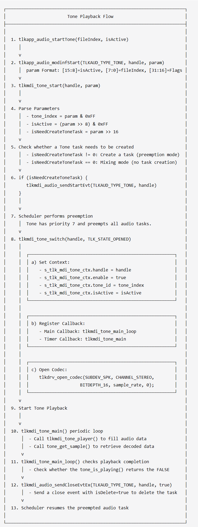
Tone Playback Integrity Assurance Mechanism
1. Busy state detection
The busy state detection of the Tone module checks two conditions simultaneously:
bool tlkmdi_tone_is_busy(void)
{
    // 1. tone_is_playing(): Is the underlying tone playing
    //    - Check the status of the decoder
    //    - Check the status of the data buffer

    // 2. s_tlk_mdi_tone_ctx.waitSyncTimer: Is the TWS sync timer waiting
    //    - Used in TWS mode to wait for the peer device synchronization

    return tone_is_playing() || s_tlk_mdi_tone_ctx.waitSyncTimer;
}
2. Timer callback mechanism
Tone uses a dual-callback mechanism to ensure playback integrity:
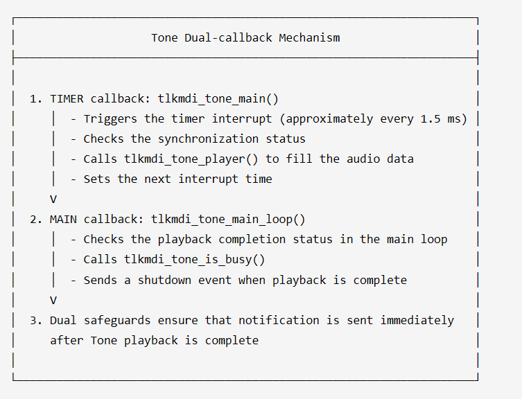
Timer callback code:
void tlkmdi_tone_main(void)
{
    // 1. check TWS sync status
    bool isWait = tlkmdi_tone_waitSyncPlay();
    if(isWait){
        return;  // TWS sync timer is waiting, not playing
    }

    // 2. set next interrupt time
    tlkmdi_audio_task_set_next_irq(1500);  // 1.5ms

    // 3. execute Tone play
    tlkmdi_tone_player();
}

void tlkmdi_tone_main_loop(void)
{
    if (tlkmdi_tone_is_busy()) {
        return;  // still playing
    }
    // play complete, send close event
    tlkmdi_audio_sendCloseEvtEx(TLKAUD_TYPE_TONE, 0xffff, true);
}
3. TWS synchronization mechanism
For TWS (True Wireless Stereo) scenarios, Tone playback requires synchronization between the left and right earbuds:
static void tlkmdi_tone_waitSyncPlayStart(uint8_t tone_id)
{
    // request TWS sync play
    int ret = tlkmdi_audio_hostif_tone_requestSyncPlay(tone_id);
    if(ret == TLK_ENONE){
        // TWS sync request success, start wait timer
        // wait time: TLKMDI_TONE_WAIT_SYNC_TIMEOUT_MS = 150ms
        s_tlk_mdi_tone_ctx.waitSyncTimer = TLKMDI_TONE_WAIT_SYNC_TIMEOUT_MS / 10;
    } else {
        s_tlk_mdi_tone_ctx.syncTick = 0;
    }
}

// TWS sync wait check
static bool tlkmdi_tone_waitSyncPlay(void)
{
    if (s_tlk_mdi_tone_ctx.waitSyncTimer == 0) {
        return false;  // no need to wait
    }

    if (s_tlk_mdi_tone_ctx.syncTick != 0) {
        // sync signal received
        return false;
    }

    // TWS sync wait timeout check in tlkmdi_tone_main()
    return true;
}
4. Playback completion notification chain
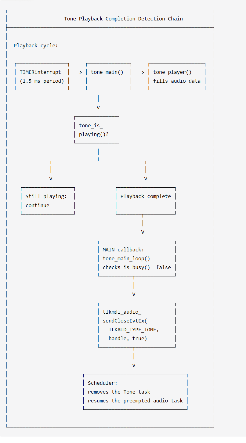
Tone and Music Mixing
Tone can be mixed with Music during playback to achieve a "background music + prompt tone" effect.
1. Mixing detection flow
bool tlkapp_audio_startTone(uint8_t fileIndex, uint8_t isActive)
{
    uint32_t isNeedCreateToneTask = 0xFFFF0000;  // default need create task

    const tlkapp_audioScheduler_node_t *nowTask =
        tlkapp_audioScheduler_getRunningTask();

    if (nowTask != NULL) {
        // query current task if support tone mix
        uint8_t opcode = TLKAUD_OPCODE_IS_SUPPORT_TONE_MIX;
        bool res = tlkapp_audio_modinfOperate(
            (uint16_t)nowTask->taskId,
            (uint16_t)nowTask->info.optype,
            &opcode, 1);

        if(res == true){
            // support tone mix, no need to create an independent task
            isNeedCreateToneTask = 0;
        }
    }

    uint32_t param = isNeedCreateToneTask | fileIndex;
    param |= (uint32_t)isActive << 8;

    return tlkapp_audio_modinfStart(TLKAUD_TYPE_TONE, TLK_INVALID_HANDLE, param);
}
2. Mixing scenario analysis
| Scenario | Music Mixing Support | isNeedCreateToneTask | Effect |
|---|---|---|---|
| Play Tone | Music does not support mixing | 0xFFFF0000 | Preempt Music; Tone plays exclusively |
| Play Tone | Music supports mixing | 0 | Music continues playing; Tone is mixed into the output |
| Play Tone | No Music playback | 0xFFFF0000 | Tone plays normally |
| TWS-synchronized Tone | TWS does not support mixing | 0xFFFF0000 | Local playback starts after the synchronization wait times out |
3. Mixing implementation
When mixing is supported, Tone data and Music data are mixed at the audio output layer:
// in tlkmdi_tone_player(), mix tone with music
static void tlkmdi_tone_player(void)
{
    uint16_t samples_num = 128;

    // clear tone output buffer
    memset(pcm16_tone, 0, sizeof(pcm16_tone));

    if (tone_is_playing()) {
        // get tone decoded samples
        tone_get_sample(pcm16_tone, samples_num * sizeof(tone_int),
                        s_tlk_mdi_tone_ctx.sample_rate);

        // mix tone with music in output buffer
        // mix algorithm: pcm_out = pcm_music + pcm_tone (with overflow protection)
        for (i = 0; i < samples_num * 2; i++) {
            int32_t mixed = pcm_music[i] + pcm16_tone[i];
            // overflow protection
            if (mixed > 32767) mixed = 32767;
            if (mixed < -32768) mixed = -32768;
            pcm_output[i] = mixed;
        }
    }
}
Appendix
Quick Reference for Key APIs
1. Core scheduler API
// init audio scheduler
int tlkapp_audioScheduler_init(uint32_t cfg);

// task management
int tlkapp_audioScheduler_addTask(uint32_t taskId, tlkapp_audioScheduler_taskInfo_t info);
int tlkapp_audioScheduler_updateTask(uint32_t taskId, tlkapp_audioScheduler_taskInfo_t info, uint32_t sameDevTaskId);
int tlkapp_audioScheduler_pauseTask(uint32_t taskId);
int tlkapp_audioScheduler_resumeTask(uint32_t taskId);
int tlkapp_audioScheduler_deleteTask(uint32_t taskId);

// query task information
const tlkapp_audioScheduler_node_t *tlkapp_audioScheduler_getRunningTask(void);
const tlkapp_audioScheduler_taskInfo_t *tlkapp_audioScheduler_getTaskInfo(uint32_t taskId);
uint8_t tlkapp_audioScheduler_getCurOptype(void);

// scheduler task management
const tlkapp_audioScheduler_node_t *tlkapp_audioScheduler_SchPausedTask(bool isAutoSch, uint8_t audioType);
const tlkapp_audioScheduler_node_t *tlkapp_audioScheduler_roundRobin(void);
2. Module interface API
// module interface
bool tlkapp_audio_modinfSwitch(TLKAUD_TYPE_ENUM optype, uint16_t handle, uint8_t status);
int  tlkapp_audio_modinfStart(TLKAUD_TYPE_ENUM optype, uint16_t handle, uint32_t param);
int  tlkapp_audio_modinfClose(TLKAUD_TYPE_ENUM optype, uint16_t handle);
bool tlkapp_audio_modinfOperate(uint16_t handle, TLKAUD_TYPE_ENUM optype, uint8_t *pData, uint16_t dataLen);
3. Audio event API
// send audio event
int tlkmdi_audio_sendStartEvt(uint8_t audChn, uint16_t handle);
int tlkmdi_audio_sendStartEvtEx(uint8_t audChn, uint16_t handle, uint8_t priority);
int tlkmdi_audio_sendCloseEvt(uint8_t audChn, uint16_t handle);
int tlkmdi_audio_sendCloseEvtEx(uint8_t audChn, uint16_t handle, uint8_t isDelete);
Audio Path
Audio Path Block Diagram
The Audio path consists of the following modules: tlkapp/audio, tlkmw/audio, and tlkmw/sys_dev/codec. The block diagram is shown below.
- tlkapp/audio contains message processing, module interfaces, audio control interfaces, and audio task scheduling logic.
- tlkmw/audio contains implementations for various audio scenarios, as shown in the figure.
- tlkmw/sys_dev/codec contains codec-related code.
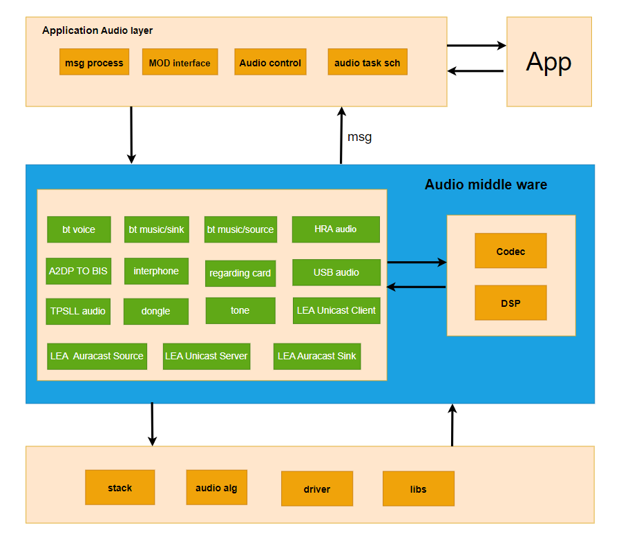
Audio Path Hardware Modules
1) Timer
TIMER0 is used as the main timer for audio processing.
The audio timer APIs are as follows:
// Start the audio timer
void tlkmdi_audio_start_timer(void)
// Stop the audio timer
void tlkmdi_audio_stop_timer(void)
// Set the capture timer for the audio timer
void tlkmdi_audio_set_timer(uint32_t cap_tick)
// Set the next interrupt time for the audio task
void tlkmdi_audio_task_set_next_irq(uint32_t tus)
// Set and Start the audio timer
void tlkmdi_audio_setup_and_start_timer(void)
2) CODEC
CODEC includes ADC (Analog-to-Digital Converter) and DAC (Digital-to-Analog Converter):
- Input path (ADC): Supports analog microphones (AMIC), digital microphones (DMIC), and line input (LINEIN). It can be configured for single-channel (A1/A2/B1/B2) or dual-channel (A1_A2, B1_B2) operation, supports 16-bit/24-bit data formats and sampling rates of 16 kHz, 44.1 kHz, 48 kHz, 96 kHz, 192 kHz, 384 kHz, and 768 kHz.
- Output Path (DAC): Supports single-channel or dual-channel output and connects to headphones/speakers.
- Main initialization APIs:
// Power on the ADC/DAC
void audio_codec0_power_on(audio_codec0_power_e power_mode, audio_codec0_volt_supply_e volt)
// Configure ADC input parameters
void audio_codec0_input_init(audio_codec0_input_config_t *input_config)
// Configure DAC output parameters
void audio_codec0_output_init(audio_codec0_output_config_t *output_config)
// ADC analog/digital gain
void audio_codec0_set_input_again/dgain(audio_codec0_input_select_e input, audio_codec0_input_again_e gain)
// DAC analog/digital gain
void audio_codec0_set_output_again/dgain(audio_codec0_output_select_e output, audio_codec0_output_again_e gain)
3) DMA
DMA is used for efficient audio data transfer without CPU intervention:
- RX DMA (e.g., DMA0): Transfers audio data from the FIFO to the memory buffer
gpTlkDrvCodecMicBuffer. - TX DMA (e.g., DMA1): Transfers data from the memory buffer
gpTlkDrvCodecSpkBufferto the FIFO for DAC output.
4) FIFO
FIFO serves as an intermediate buffer for the audio data stream:
- RX FIFO (e.g., FIFO0): Receives data from the CODEC ADC or I2S.
- TX FIFO (e.g., FIFO1): Sends data to the DAC or I2S.
Audio Path Directory Structure
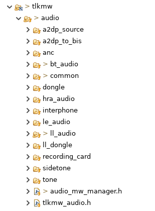
- The Audio Path code is located in the
tlkmw/audiodirectory, which contains applications for various audio scenarios. a2dp_sourcecontains the A2DP Source functionality. The audio source can be a local sine wave, LINEIN, or UAC.a2dp_to_biscontains the A2DP In to LE BIS Out functionality.ANCcontains audio applications for ANC scenarios, including BT Music, BT Voice, and TPSLL Audio.bt_audiocontains BT A2DP Sink and BT Voice functionality.donglecontains USB-to-headset functionality, with two audio paths: BT Voice and A2DP Source.hra_audiocontains hearing-aid functionality, including a hearing-aid-only path, BT Music path, and BT Voice path.interphonecontains functionality related to mesh helmet applications.le_audiocontains BLE CIS and BLE BIS functionality.ll_audiocontains the headset-side functionality of TPSLL Audio.ll_donglecontains the dongle-side functionality of TPSLL Audio.recording_cardcontains functionality for recording card applications.tonecontains Tone playback functionality.commoncontains logic shared by various audio scenarios, such as timer management, memory allocation, and DSP path code.
The following describes the tlkmw/audio/common directory. It contains the DSP driver code for D25F. Currently, only the BT Voice and TPSLL Voice uplink paths use the DSP. tlkmdi_audmem.c contains memory allocation functions used by the audio paths and algorithms. tlkmdi_audio_common.c contains common functions shared by various audio scenarios, such as the Audio IRQ task, main loop, and DSP main loop. The host_interface folder contains the logic for interacting with the stack.
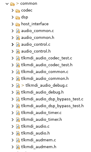
Audio Path MDI Interface
The interface between the Application and Middleware is called MDI. All audio tasks share a common set of audio control logic. Each task registers its interfaces with the Application, and the Application distinguishes different tasks by type.
typedef struct
{
    int (*Init)(void);
    bool (*Switch)(uint16_t handle, uint8_t status);
    void (*Timer)(void);
    bool (*IsBusy)(void);

    int (*Start)(uint16_t handle, uint32_t param);
    int (*Close)(uint16_t handle);
    bool (*ToNext)(void);
    bool (*ToPrev)(void);
    bool (*operate)(uint16_t handle, uint8_t opcode, uint8_t *pdata, uint16_t dataLen);
} tlkapp_audio_modinf_t;
The following shows the interface definitions for the Module Interface in tlkapp/audio. Different audio scenarios define different interfaces. The following is the interface definition for the BT Music scenario.
tlkapp/audio calls Switch to enter or exit an audio scenario, and calls the audio scenario control interfaces through Start, Close, ToNext, ToPrev, and Operate.
static const tlkapp_audio_modinf_t sTlkAppAudioCCBTMusicModinf = {
    .Init    = tlkmdi_bt_music_init,
    .Switch  = tlkmdi_bt_music_switch,
    .IsBusy  = tlkmdi_bt_music_is_busy,
    .Start   = tlkmdi_bt_music_start,
    .Close   = tlkmdi_bt_music_close,
    .ToNext  = tlkmdi_bt_music_next,
    .ToPrev  = tlkmdi_bt_music_previous,
    .operate = tlkmdi_bt_music_operate,
};
The above shows the interfaces registered for the BT Music scenario.
    bt_music_audio_path_init();
    bt_audio_register_get_pcm_data_callback(bt_music_get_playback_data);
    tlkmdi_audio_register_cb(TLKMDI_AUDIO_CB_TIMER,bt_audio_main);
    tlkmdi_audio_register_cb(TLKMDI_AUDIO_CB_MAIN,bt_audio_main_loop);
    bt_audio_task_register_run_cb(NULL, 1);
The above shows the main logic of tlkmdi_bt_music_switch. It initializes memory and algorithms, registers the Timer IRQ interrupt handler in bare-metal projects, registers the Audio IRQ task event handler in RTOS projects, and registers the main loop handler.
Headset-Side Audio Path
The figure below shows the MIC uplink path and speaker downlink path in the cc-headset project.
- The MIC uplink path uses multiple algorithms. Except for NN_NS, which runs on the DSP, all other algorithms run on the D25F. By default, only the NN algorithm is enabled.
- In the speaker downlink path, ASRC is the resampling algorithm from 44.1 kHz to 48 kHz. The TL751x uses a hardware ASRC, while other chips require a software implementation.
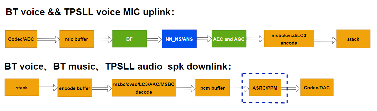
Dongle-Side Audio Path
1. Dongle Audio Path operation
After being connected to a USB host, the Dongle enumerates as a USB microphone device and a USB speaker device. During normal operation, the Dongle processes audio received from the headset and uploads it to the USB host through the USB microphone path. It also processes audio data received through the USB speaker path and sends it to the headset.
2. Dongle Audio Path Flow
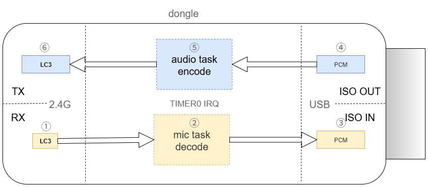
(1)The Dongle receives single-channel, 16 kHz LC3-encoded MIC data packets from the headset.
(2)The MIC task primarily performs decoding, data alignment, sample rate conversion, and volume adjustment on the MIC data.
(3)The USB ISO IN handler sends the processed data to the USB host.
(4)The USB ISO OUT handler receives 48 kHz PCM-format speaker data from the USB host.
(5)The Audio task primarily performs volume adjustment and data alignment on the speaker data, and encodes it into LC3 format.
(6)The LC3-encoded speaker data packets are sent to the headset.
Mixing Logic
The CC-TWS and CC-headset projects support dual-mode audio mixing. The mixing of BT Music and TPSLL Audio, as well as the mixing of BT Voice and TPSLL Audio, is enabled by default. The mixing functionality can be enabled or disabled using the LE_AUDIO_BT_MUSIC_MIX_ENABLE or LE_AUDIO_BT_VOICE_MIX_ENABLE macro, respectively. These macros are located in tlkmw/audio/audio_mw_manager.h. The audio format is 48 kHz, 24-bit.
For BT Music, the mix_ll_audio_stereo API is called to mix the BT Music audio with TPSLL Audio.
/**
 * @brief      Mix asynchronous audio and Bluetooth music in async_audio bt_music mix mode.
 * @param[in]  p0 - Pointer to first data buffer.
 * @param[in]  p1 - Pointer to second data buffer.
 * @param[in]  samples_num - Number of samples to mix.
 * @return     Number of mixed samples.
 */
uint16_t mix_ll_audio_stereo(int16_t *p0, int16_t *p1, uint16_t samples_num);
CODEC Interface
The CODEC code is located in the tlkmw/sys_dev/codec directory. tlkdrv_codec.c serves as the abstraction layer, where the speaker buffer and MIC buffer are defined. The other files contain CODEC drivers for different chips.
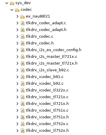
const tlkdrv_codec_modinf_t gcTlkDrvIcodecInf = {
    .IsOpen = tlkdrv_icodec_isOpen,
    .Init   = tlkdrv_icodec_init,
    .Open   = tlkdrv_icodec_open,
    .Close  = tlkdrv_icodec_close,
    .Config = tlkdrv_icodec_config,
};
The CODEC driver registers with the abstraction layer through the code module interface. The application opens the CODEC using tlkdrv_open_codec(), writes PCM data to the CODEC speaker buffer using tlkdrv_codec_fillSpkBuff(), and obtains MIC data using tlkdrv_codec_readMicData().
Audio Algorithm
Algorithm Overview
The following audio algorithms are mainly used in this SDK:
- SBC (Sub-band Coding)
- mSBC (Modified Sub-band Coding)
- CVSD (Continuous Variable Slope Delta Modulation)
- AAC (Advanced Audio Coding)
- LC3 (Low Complexity Communication Codec)
- LC3p (Low Complexity Communication Codec Plus)
- Opus (Opus Interactive Audio Codec)
- EQ (Equalizer)
- BF (Beamforming)
- AEC (Acoustic Echo Cancellation)
- NS (Noise Suppression)
- AGC (Automatic Gain Control)
- PLC (Packet Loss Concealment)
- ASRC (Asynchronous Sample Rate Conversion)
Algorithm Path Block Diagram
Using a BT/TPSLL dual-mode application as an example, the audio algorithms are divided into the following three modes according to the different operating states of the audio path, as shown in the figure:
Voice Uplink is the voice uplink path. BT supports two encoding algorithms, mSBC and CVSD, while TPSLL supports two encoding algorithms, LC3 and LC3p. The voice algorithm path is BF->NN_NS/ANS->AEC->AGC. The noise reduction algorithm provides two options: neural network noise suppression (NN_NS) and traditional noise suppression (ANS).
Voice Downlink is the voice downlink path. BT supports two decoding algorithms, mSBC and CVSD, while TPSLL supports two decoding algorithms, LC3 and LC3p. PLC is the packet loss concealment algorithm corresponding to the decoder. ASRC is used for audio data sample rate conversion to match the data streams of the BT and TPSLL audio paths during mixing.
Music Downlink is the music downlink path. BT supports two decoding algorithms, mSBC and CVSD, while TPSLL supports two decoding algorithms, LC3 and LC3p. The ASRC algorithm is the same as described above. EQ is used to adjust the sound effects.
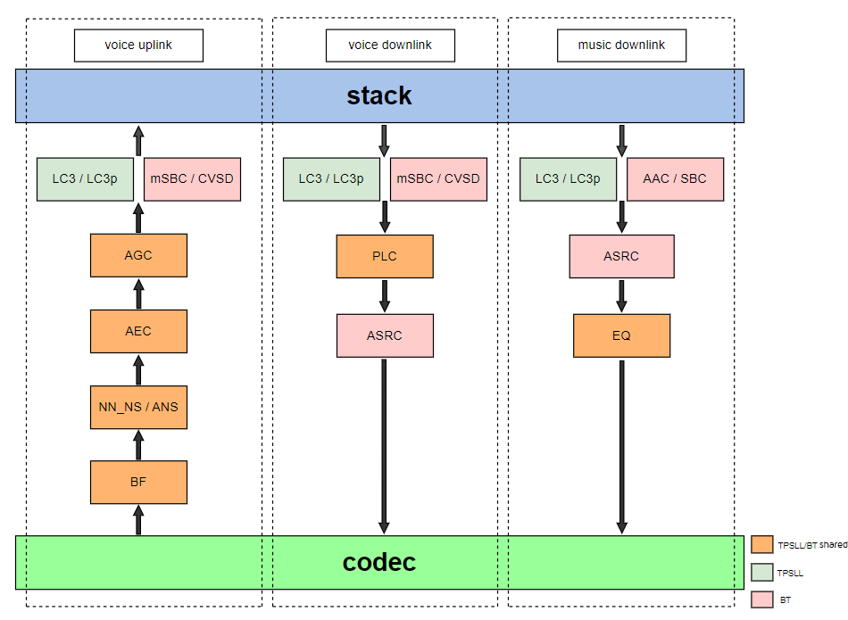
Algorithm Interfaces
To facilitate unified management of various audio algorithms, the SDK provides a set of standardized algorithm interfaces to simplify algorithm invocation and the integration of new algorithms. The interface code is shown below:
typedef struct {
    /* Reset algorithm parameter settings */
    uint8_t(*audio_alg_param_reset)(void);

    /* Set algorithm parameter settings */
    uint8_t(*audio_alg_param_set)(uint8_t type, void *param);

    /* Get the memory size used by the algorithm */
    uint16_t(*audio_alg_get_size)(uint8_t channel);

    /* Init channel: mono or stereo */
    int8_t(*audio_alg_init)(uint8_t *p_buff, uint8_t channel);

    /* deinit */
    int8_t(*audio_alg_deinit)(void);

    /* Alg process */
    int (*audio_alg_process)(uint8_t *ps, uint8_t *pd, uint16_t len, uint8_t width, uint8_t channel);
} audio_alg_interface_t;
An array of structures is defined to centralize the algorithms. The corresponding algorithm interface can be obtained using the specific algorithm index. The algorithm types are defined by the enumeration shown below:
const audio_alg_interface_t audio_alg_if[ALG_TYPE_MAX] = {
    //alg1
    //alg2
    //...
}

typedef enum {
    ALG_AAC_DEC = 0,
    ALG_SBC_ENC,
    ALG_SBC_DEC,
    ALG_LC3_ENC,
    ALG_LC3_DEC,
    ALG_CVSD_ENC,
    ALG_CVSD_DEC,
    ALG_MSBC_ENC,
    ALG_MSBC_DEC,
    ALG_LC3_PLUS_ENC,
    ALG_LC3_PLUS_DEC,
    ALG_OPUS_ENC,
    ALG_OPUS_DEC,
    ALG_LHDC_DEC,
    ALG_EQ,
    ALG_ADPCM,
    ALG_ASRC,
    ALG_DRC,
    ALG_AEC,
    ALG_ENC,
    ALG_ANS,
    ALG_SPK_ANS,
    ALG_HYBRID,
    ALG_AGC,
    ALG_ASRC_48TO16_16BIT,
    ALG_ASRC_48TO16_24BIT,
    ALG_ASRC_16TO48_16BIT,
    ALG_ASRC_16TO48_24BIT,
    ALG_ASRC_48TO441,
    ALG_ASRC_441TO48_16BIT,
    ALG_ASRC_441TO16_16BIT,
    ALG_ASRC_16TO441_16BIT,
    ALG_ASRC_48TO32_16BIT,
    ALG_ASRC_32TO48_16BIT,
    ALG_ASRC_32TO16_16BIT,
    ALG_PPM_SPK,
    ALG_PPM_MIC,
    ALG_PPM_TWS_SPK,
    ALG_LC3_24BIT_ENC,
    ALG_LC3_24BIT_DEC,
    ALG_VAD,
    ALG_PPM_SPK_24BIT,
    ALG_NN_NS,
    ALG_NN_NS_VAD,
    //ALG_PPM_MIC_24BIT,
    ALG_DEFAULT,
    ALG_TYPE_MAX
} audio_alg_type_e;
Taking the SBC decoding algorithm as an example, the following describes how an algorithm is used within the SDK:
(1) Algorithm Registration: Register the interfaces used by the algorithm in the previously defined structure array.
const audio_alg_interface_t audio_alg_if[ALG_TYPE_MAX] = {
#if TLKALG_SBC_DEC_ENABLE
    [ALG_SBC_DEC] = {
        .audio_alg_get_size = tlkalg_sbc_dec_get_size,
        .audio_alg_init = tlkalg_sbc_dec_init,
        .audio_alg_deinit = tlkalg_sbc_dec_deinit,
        .audio_alg_process = tlkalg_sbc_dec_process,
    },
#endif
}
(2) Algorithm Initialization: Allocate the required memory space from the heap based on the memory requirements of the algorithm, and initialize the algorithm using the allocated address.
audio_alg_interface_t *p_audio_alg_if = audio_alg_get_interface_by_type(ALG_SBC_DEC);

if (s_alg_sbc_dec_buffer == NULL) {
    uint16_t sbc_dec_mem_size = p_audio_alg_if->audio_alg_get_size(ALG_CHANNEL_STEREO);
    s_alg_sbc_dec_buffer      = (uint8_t *)tlkalg_malloc_func(sbc_dec_mem_size);
    if (s_alg_sbc_dec_buffer == NULL) {
        tlkapi_printf(APP_LOG_EN, "sbc dec buff alloc failed");
        return false;
    }
    p_audio_alg_if->audio_alg_init(s_alg_sbc_dec_buffer, ALG_CHANNEL_STEREO);

    tlkapi_printf(APP_LOG_EN, "sbc_dec_mem_size: %d", sbc_dec_mem_size);
}
(3) Algorithm Processing::Call the algorithm processing interface at the corresponding position in the audio path. buf_ptr points to the data to be processed, p_des points to the processed data, and the other parameters are algorithm configuration parameters.
audio_alg_interface_t *audio_alg_if_handle = audio_alg_get_interface_by_type(ALG_SBC_DEC);
ret = audio_alg_if_handle->audio_alg_process(buf_ptr, (uint8_t *)p_des, bt_music_cfg.sbc_framesize, ALG_WIDTH_16, ALG_CHANNEL_STEREO);
(4) Algorithm Reset: After the algorithm usage scenario ends, restore the algorithm parameters and release the allocated memory.
audio_alg_interface_t *p_audio_alg_if = audio_alg_get_interface_by_type(ALG_SBC_DEC);
if (s_alg_sbc_dec_buffer != NULL) {
    tlkalg_free_func(s_alg_sbc_dec_buffer);
    p_audio_alg_if->audio_alg_deinit();
    s_alg_sbc_dec_buffer = NULL;
}
Volume Adjustment
Call Scenario
In the call scenario, the volume in this SDK is adjusted using the bt_audio_control_voice_volume() function.
In the call scenario, the volume of the input audio data is adjusted sample by sample. If the current audio volume is lower than the configured volume level, the audio volume is increased; if the current audio volume is higher than the configured volume level, the audio volume is decreased. The process is shown in the figure below:
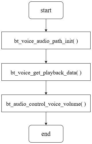
Music Scenario
In the music scenario, the volume in this SDK is adjusted using the bt_audio_control_music_volume() function.
In the music scenario, volume adjustment is performed only when the number of samples requiring volume adjustment reaches a certain threshold, which is controlled by the SAMPLES_NUM_CHANGE_VOLUME macro and is currently set to 10. When the current audio volume is lower than or higher than the configured volume level, the volume adjustment counter is incremented by 1. When the counter reaches SAMPLES_NUM_CHANGE_VOLUME, the counter is reset, and the corresponding volume adjustment is performed. The process is shown in the figure below:
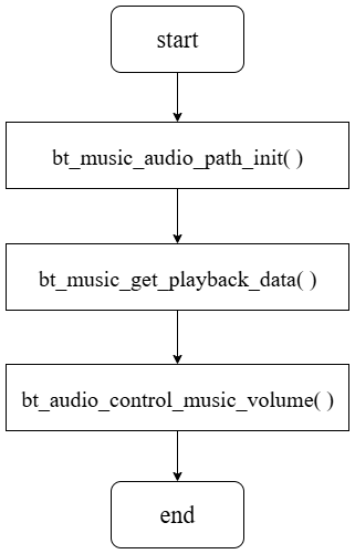
Tone Playback
Tone Creation
Tone source format: 16 kHz, mono
Tone creation tool: wave_to_tone_bin_tool_v1.0.1
Tone creation procedure:
According to the type definitions in tone.h, rename the audio sources as 1, 2, 3, … The mapping between the type values and the corresponding audio sources is shown below. After renaming the audio sources, use the pcm16to8_vol_1024.bat script to generate the Tone files. The generated files are in ADPCM format.
typedef enum
{
    TONE_PAIRING = 0,   ---> wav file 1
    TONE_CONNECTED,     ---> wav file 2
    TONE_LE_CONNECTED,
    TONE_LOW_POWER,
    TONE_RING,
    TONE_POWER_OFF,
    TONE_DISCONNECTED,
    TONE_BT_AUDIO_MUSIC_MODE,  ---> wav file 9
    TONE_BT_AUDIO_GAME_MODE,  ---> wav file 10

    MODE_MAX_TONE
} e_type_tone_t;
Tone Download
The generated Tone files can be downloaded to Flash. The download address is defined by the CONFIG_TLK_AUDIO_TONE_DOWNLOAD_ADDR macro.
#ifndef CONFIG_TLK_AUDIO_TONE_DOWNLOAD_ADDR
#define CONFIG_TLK_AUDIO_TONE_DOWNLOAD_ADDR (FLASH_R_BASE_ADDR + 0X1A0000)
#endif

#ifndef FLASH_R_BASE_ADDR
#define FLASH_R_BASE_ADDR (0x20000000)
#endif
Tone Addition
Tone files support two encoding formats: SBC and ADPCM. The playback process is the same for both formats. Taking an ADPCM-encoded Tone as an example, call tone_play() with the specified ID, such as tone_play(CONNECTED_TONE). The program then initializes the ADPCM decoder and plays the Tone.
The tone_get_sample() function is called in the BT Audio playback logic or TPSLL Audio playback logic to obtain PCM data.
DSP Usage
The DSP functionality is controlled by the TLK_MW_DSP_COMM_ENABLE macro. To enable DSP functionality, enable this macro in the app_config.h file of the corresponding example.
#define TLK_MW_DSP_COMM_ENABLE 1
The DSP uses the RAM boot method by default. The D25F transfers the DSP bin code and data to the DSP. The DSP reset vector address is DSP_FW_DOWNLOAD_FLASH_ADDR, and the DSP bin file is programmed to address 0x200000 by default.
#define DSP_FW_DOWNLOAD_FLASH_ADDR 0x2100660
DSP and D25F Dual-Core Communication Mechanism
The DSP and D25F communicate through a mailbox mechanism for transmitting IPC messages and shared memory for transmitting audio data, as shown in the figure below.
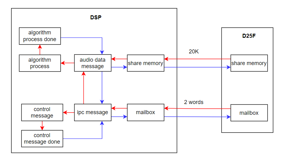
The mailbox is 2 words in length. The first 2 bytes are the message header, which contains the message type, valid data length, and checksum. The message types can be divided into control messages and audio data processing messages. The remaining 6 bytes contain valid information, which is defined according to the message type.
There are three data transmission paths between the DSP and D25F, which can be used for audio data, algorithm parameters, and other data.
typedef enum
{
    IPC_DATA_PATH_0,
    IPC_DATA_PATH_1,
    IPC_SET_PARAM_PATH_2,
    IPC_DATA_PATH_MAX,
} ipc_data_path_e;
The IPC/audio data buffer is allocated in shared memory and has a size of 20 KB. Its address is located in the DSP DRAM. Read/write pointers, algorithm types, data lengths, and other information are defined for different data paths.
The DSP receives IPC messages from the D25F in the mailbox interrupt handler, writes them to a queue, and processes the messages in the main loop.
DSP Usage Flow
Based on the DSP and D25F dual-core communication mechanism described above, the DSP can be dynamically enabled or disabled in different application scenarios. The DSP usage flow is as follows:
During audio module initialization, the DSP initialization function is called to allocate and initialize the IPC/audio data buffer, boot and start the DSP, and enable the DSP mailbox function. After the D25F completes the DSP boot process, the DSP enters the TLKDRV_DSP_STATE_BOOTING state.
void tlkmw_dsp_init(void)
{
    d25f_init_ipc_buffer();
    tlkdrv_dsp_init();
}
The DSP starts running and actively sends a handshake-done message to the D25F. After receiving the message, the D25F disables the DSP clock, and the DSP enters the TLKDRV_DSP_STATE_PAUSED state.
In an audio scenario that requires DSP processing, call the tlkmw_dsp_resume() function to enable the DSP clock. The DSP then enters the TLKDRV_DSP_STATE_RUNNING state.
The ipc_msg_register_data_process_done_cb() function is used to register a callback function for processing data returned by the DSP.
The d25f_send_audio_data_to_dsp() function writes the data to be processed on the MCU side to shared memory and triggers the DSP mailbox interrupt.
void tlkmw_dsp_resume(void)
{
    tlkdrv_dsp_resume();
}
After exiting the DSP-enabled scenario, call the tlkdrv_dsp_pause() function to put the DSP into the TLKDRV_DSP_STATE_PAUSING state. In the DSP timer of the OS, the DSP eventually transitions to the TLKDRV_DSP_STATE_PAUSED state, and the DSP clock is disabled.
void tlkdrv_dsp_pause(void)
{
    if(sTlkdrvDspState != TLKDRV_DSP_STATE_RUNNING){
        return;
    }
    sTlkdrvDspState = TLKDRV_DSP_STATE_PAUSING;
    tlksys_timer_reStart(TLKSYS_TASKID_AUDIO,&sTlkdrvDspTmr);
}
Protocol Stack and Profile Related
BT Applications
Scan Management
(1) Scan Overview
This chapter mainly introduces the basic concepts of Classic Bluetooth (hereafter referred to as BT) scan, as well as the principles and usage of scan in the SDK.
BT Scan refers to periodically tapping and listening for Inquiry messages sent by surrounding terminals when not connected, in order to discover devices available for pairing and collect key information (Bluetooth address, device category, clock offset, page scan mode, etc.). This process is only used in the discovery phase before establishing a connection and is different from the “advertising–scanning” concept in BLE. It does not involve the transmission or reception of advertising packets.
Two main usage methods:
- Inquiry Scan
Peripheral devices (headset, audio, etc.) periodically open windows to monitor GIAC/DIAC queries sent by central devices (such as mobile phones and laptops). After being queried, it returns an FHS packet for the central to obtain the address and clock, and then proceeds to the page process to establish an ACL link.
- Page Scan
If the peripheral allows connection, it continues to periodically scan the page packet after the query is completed. The central uses the clock offset obtained earlier for fast paging to establish the link.
Application scenarios
- First pairing: After the phone initiates an inquiry, the earphones are found. The user selects the earphones to connect and initiates the page, which triggers pairing/binding.
- Reconnection: Bound devices can directly initiate pages using the address without needing to be re-inquired. After the earphones and phone pair successfully for the first time, the phone saves the Bluetooth device address and link key to the pairing list. If the earphones are restarted or enter the connected range, users only need to click on their existing earphone device on the phone to skip the inquiry stage and start the page process directly.
In short, BT Scan operates through a "query-response" mechanism: the peripheral side initiates Inquiry/Page Scan, the central side issues an Inquiry to complete device discovery, then establishes a link via the page to enable subsequent pairing, authentication, and profile connection.
(2) Scan Usage
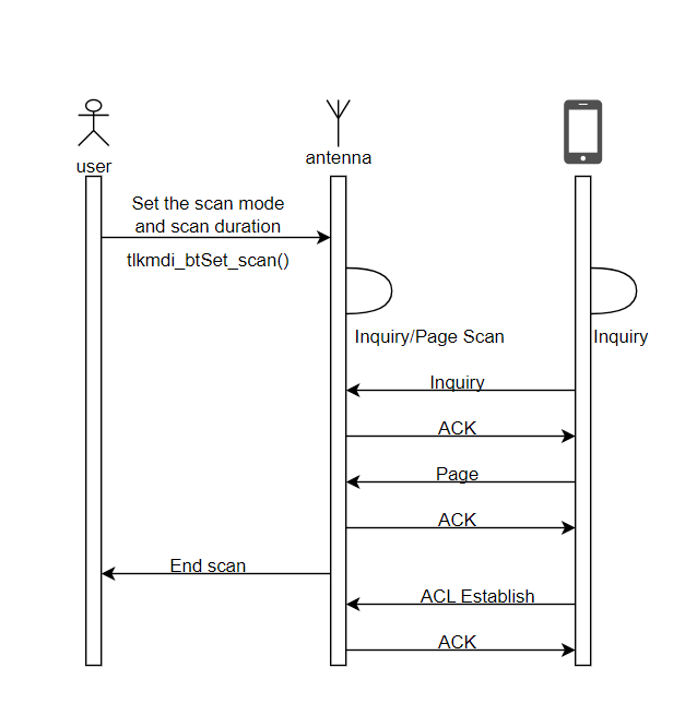
/**
 * @brief       This function is called by the application to set the Bluetooth scan mode.
 * @param[in]   scan_value - the scan mode to be set.
 * @param[in]   time       - time duration, if scan_value is TLKMDI_BTSCAN_MODE_BOTH_DISABLE time will be neglect. Unit:S.
 *                           If value is not TLKMDI_BTSCAN_MODE_BOTH_DISABLE and time is set as 0, the scan will always be on.
 *                           If time is set as 0xFFFF, then only update the scan value; the timeout continues to count down.
 * @return      none.
 * @note        If the scan mode is already set to the same value, the function returns mode immediately. If the scan mode is different,
 *              the function sends a HCI command to set the scan mode. If the HCI command is sent successfully, the function sets a timer
 *              to wait for the HCI command complete event. If the HCI command fails, the function sets the scan mode as pending and
 *              waits for the next scan mode change. If the scan mode is set to TLKMDI_BTSCAN_MODE_BOTH_DISABLE, the function stops the timer.
 *              If the scan mode is set to a value other than TLKMDI_BTSCAN_MODE_BOTH_DISABLE, the function starts the timer with the specified time.
 */
void tlkmdi_btSet_scan(uint8_t scan_value, uint16_t time)
The key function of the Scan management module, mainly used to set the current scan mode and timeout. After calling this function, a HCI_Write_Scan_Enable HCI command is sent to the BT controller.
Special Note: This function is non-thread-safe and cannot be called from an interrupt. In an RTOS environment, if this interface is called from other non-thread tasks such as audio, system, or user, it must be sent to the host thread via a message queue to ensure secure execution.
#define TLKMDI_BTSCAN_TIME_UNIT 1000000 // 1s
scan timeout = time * TLKMDI_BTSCAN_TIME_UNIT // uinit:s
The interval of tlkmdi_btSetScan_timer is triggered every 1s. Its timeout period is determined by the second parameter time of tlkmdi_btSet_scan.
typedef enum
{
    TLKMDI_BTSCAN_MODE_BOTH_DISABLE,
    TLKMDI_BTSCAN_MODE_INQUIRY_SCAN,
    TLKMDI_BTSCAN_MODE_PAGE_SCAN,
    TLKMDI_BTSCAN_MODE_BOTH_SCAN,
} TLKMDI_BTSCAN_ACTIVE_MODE_ENUM;
TLKMDI_BTSCAN_ACTIVE_MODE_ENUM describes the scan mode, which currently offers Both Scan (Inquiry Scan + Page Scan), Inquiry Scan, Page Scan, and Off Scan. Except for TLKMDI_BTSCAN_MODE_BOTH_DISABLE, if you want to set the selected mode to be valid long-term, you can set the corresponding interface's time input to 0 until it is explicitly closed or the mode switches again.
typedef struct
{
    uint8_t         cur_scan_state;
    uint8_t         waiting_confirm_value : 4; /* waiting hci set scan command complete */
    uint8_t         waiting_flag          : 2; /* waiting hci set scan command complete */
    uint8_t         pending_scanflag      : 2;
    uint16_t        waiting_confirm_value_time;
    uint8_t         pending_scan_value;        /* during waiting hci set scan command complete, system set a new value */
    uint8_t         reserve[3];
    uint16_t        pending_scan_value_time;
    uint16_t        timeout;                   /* the number of 1s unit */
    TlkApiTimer_t   timer;
} tlkmdi_bt_scan_t;
tlkmdi_bt_scan_t describes the context of the scan state machine and supports both “immediate effect” and “asynchronously waiting for HCI completion” scenarios. Any scan request first updates the waiting_confirm_value field and sends HCI. After tlkmdi_btSetScan_hciCmdEvt_cb is triggered, write waiting_confirm_value into the cur_scan_state, then check pending_scanflag. If it is set, a new HCI configuration is initiated immediately. The new mode received while waiting is not discarded, but is stored in the pending_scan_value, ensuring the "last configuration" finally takes effect. When timeout decreases to 0, it automatically switches to TLKMDI_BTSCAN_MODE_BOTH_DISABLE and notifies the application layer through the registration callback.
(3) API Description
void tlkmdi_btScan_process_init(void);
This function is used to initialize the scan subsystem. A timer is created, with a period defined by the macro TLKMDI_BTSCAN_TIME_UNIT (typically 1 s), and the callback is registered as tlkmdi_btSetScan_timer.
This timer is responsible for decreasing scan timeout counts, triggering automatic shutdown logic, and retrying pending requests, serving as the time benchmark for the entire "timeout-auto-stop" mechanism.
int tlkmdi_btSetScan_hciCmdEvt_cb(uint8_t *pData, uint16_t dataLen);
This function is the completion event callback for HCI_Write_Scan_Enable commands, responsible for changing the "asynchronous result" to the "formal state" and handling any "pending request" chains.
-
Status verification
- If status == BTH_HCI_ERROR_NONE and the local device is indeed in waiting state (
waiting_flag ≠ 0), immediately upgradewaiting_confirm_valueto the current effective modecur_scan_state. If the new mode is TLKMDI_BTSCAN_MODE_BOTH_DISABLE, the timer is stopped immediately and the timeout counter is cleared. Otherwise, the timer is restarted. If the upper layer has specifiedtime = 0xFFFF(only update mode, no duration reset), the original countdown is retained; otherwise, the newwaiting_confirm_value_timeis reloaded.
- If status == BTH_HCI_ERROR_NONE and the local device is indeed in waiting state (
-
Clear waiting fields
- Regardless of success or failure, the
waiting_flagand related backup values are cleared to ensure that the next configuration can proceed normally.
- Regardless of success or failure, the
-
Chain trigger
- If a new request is cached (
pending_scanflag ≠ 0) during the waiting period, the corresponding HCI command is immediately issued. If the send succeeds, it enters the waiting state again; if it fails, the error is printed, and the cache is discarded. This enables a reliable strategy of consecutive configuration without packet loss and consistent final state.
- If a new request is cached (
void tlkmdi_btSet_scan(uint8_t scan_value, uint16_t time);
This function is used to dynamically switch scan modes. By setting the target mode and duration, the function handles three tasks at the lower layer: "immediate effect," "asynchronous waiting for HCI completion," and "automatic timeout-based disable".
-
If the request mode matches the current active mode, it returns directly without any additional operations.
-
If not, immediately issue an HCI command and update the expected mode and timeout value to the waiting domain of the tlkmdi_bt_scan_t control block; After the command is successfully sent, the timer is activated, decreasing the remaining duration over a 1-second period and monitoring the BTH_EVTID_SET_SCAN_CMD_COMPLETE event.
-
New requests received while waiting for HCI return are cached, and once the current command is completed, the next round of setup is automatically initiated to ensure the "last configuration" is executed.
-
Special time parameter: when
timeis 0, the duration is permanently valid until the next explicit call; whentimeis 0xFFFF, only the mode value is updated, without resetting the internal countdown, used for the "renewal" scenario.
When the internal countdown reaches 0, the module automatically closes scanning and notifies the application through the registered callback, providing a complete "one-call configuration with automatic timeout shutdown" mechanism.
uint8_t tlkmdi_btGetScan_state(void);
Get the current scan status. When waiting_flagis set, it returns to the current scan mode and refers to TLKMDI_BTSCAN_ACTIVE_MODE_ENUM; When pending_scan_value_time is not 0, it returns the current remaining time; if neither condition is satisfied, the value of pending_scan_value_time is returned.
uint16_t tlkmdi_btscan_getRemainedScanTime(void);
Get the remaining scan time.
uint8_t tlkmdi_btscan_getCurScanState(void);
Get the current scan mode and refer to TLKMDI_BTSCAN_ACTIVE_MODE_ENUM.
Reconnection Management
(1) Reconnection Overview
The BT reconnection mechanism is triggered when the device powers on or when the ACL link is disconnected due to a timeout. The SDK adopts a strategy combining active reconnection and passive waiting. It first continuously pages the target device for 10 seconds. If unsuccessful, it switches to page scan mode for 2 seconds to accept paging requests from the remote device. Together, these two stages constitute one retry cycle of 12 seconds. Power-on reconnection by default limits the number of retries to 3, with a total timeout of 36 seconds. Once a link is successfully established during either the Page or Page Scan stage, the reconnection process is terminated immediately, and the device exits reconnection modes.
#ifndef TLKMDI_BTRECON_RETRY_NUM_POWERON
#define TLKMDI_BTRECON_RETRY_NUM_POWERON        3       // power on default retry number
#endif
#ifndef TLKMDI_BTRECON_RETRY_NUM_LINK_LOSS
#define TLKMDI_BTRECON_RETRY_NUM_LINK_LOSS      25      // ACL link loss(ACL-8) default retry number
#endif

(2) Reconnection Usage
#define TLKMDI_BTRECON_CHECK_INTERVAL 5000
The interval of the reconnection state machine monitoring timer is 5 ms by default. The operation of the state machine (tlkmdi_btRecon_check_timer) is described in detail below.
#define TLKMDI_BTRECON_PAGE_INTERVAL 10000000
The interval of the reconnection process management timer is 10 seconds by default. The operation of this timer (tlkmdi_btRecon_timer) is also described in detail below.
#define TLKMDI_BTRECON_INTERVAL_TIME 2000000
After each page stage in the reconnection process, the duration of the page scan is 2 seconds by default.
typedef enum
{
    TLKMDI_BTRECON_STATE_IDLE = 0,
    TLKMDI_BTRECON_STATE_START,
    TLKMDI_BTRECON_STATE_PAGE,
    TLKMDI_BTRECON_STATE_WAIT_PAGE_CANCEL,
    TLKMDI_BTRECON_STATE_INTERVAL,
    TLKMDI_BTRECON_CANCEL_SCAN,
    TLKMDI_BTRECON_STATE_WAIT_PROFILE,
    TLKMDI_BTRECON_STATE_WAIT_STOP,
} TLKMDI_BTRECON_STATE_ENUM;
TLKMDI_BTRECON_STATE_ENUM describes the complete lifecycle of the reconnection state machine. The meanings of each state are as follows:
| Status | Description |
|---|---|
| TLKMDI_BTRECON_STATE_IDLE | Idle reconnection state. Power-on initialization, manual user cancellation, or successful reconnection, it remains here waiting for the application layer to trigger. |
| TLKMDI_BTRECON_STATE_START | Reconnection has been triggered. It starts to retrieve the pairing list, initialize the timer and resources, and prepare to enter the page. |
| TLKMDI_BTRECON_STATE_PAGE | Active Page stage. The target device is continuously paged for up to 10 seconds. If successful, the state transitions to WAIT_PROFILE; otherwise, it enters WAIT_PAGE_CANCEL upon timeout. |
| TLKMDI_BTRECON_STATE_WAIT_PAGE_CANCEL | This page is being canceled. After issuing the HCI cancel command, wait for Command Complete to ensure the hardware has exited the page. |
| TLKMDI_BTRECON_STATE_INTERVAL | Page Scan stage. Stop the page and enter page scan for 2 s, allowing peer reverse paging; When the time is up, complete a retry. |
| TLKMDI_BTRECON_CANCEL_SCAN | Terminate page scan state. When a stop‑reconnection request is received during page scan, wait for exit completion. |
| TLKMDI_BTRECON_STATE_WAIT_PROFILE | The ACL has been established, waiting for the upper-layer profiles (A2DP/AVRCP/HFP) to complete connection and configuration; If successful, the connection is terminated; if it fails, the connection is retried or downgraded. |
| TLKMDI_BTRECON_STATE_WAIT_STOP | Upon receiving a forced stop instruction, all links are disconnected, waiting for the underlying event to confirm complete exit, and finally returning to IDLE. |
The state machine loops through IDLE, PAGE, WAIT_PAGE_CANCEL, INTERVAL, START up to retry_num times; If any connection is successful or the application is forcibly stopped, the app jumps early to WAIT_PROFILE or WAIT_STOP, ensuring the reconnection process is controllable, interruptible, and resources released promptly.
typedef struct
{
    uint8_t         retry_num;
    uint8_t         state;
    uint8_t         pageAddr[6]; //The device to be connected back.

    uint32_t         devClass;
    TlkApiTimer_t  timer_recon;
    TlkApiTimer_t  timer_state_check;
} tlkmdi_btrecon_t;
tlkmdi_btrecon_t is the context control block of the BT reconnect module, recording key information: the reconnection target, retry strategy, and timers:
| Field | Description |
|---|---|
| retry_num | Remaining retry count. Decrement by 1 upon completion of each "page + page scan" cycle. When the count reaches 0, stop reconnection and report a failure. |
| state | Current reconnection state machine value, corresponding to TLKMDI_BTRECON_STATE_ENUM, used for driving state switching. |
| pageAddr[6] | Bluetooth address of the target device. When the reply starts, the pairing list writes it, and all subsequent pages are initiated to that address. |
| devClass | Class of Device for target devices, which can be used to quickly verify device types or determine reconnection strategies. |
| timer_recon | Feedback timer, responsible for rhythm control of "page 10s -> page scan 2s"; Timeout means pushing the state machine into the next substate or retrying. |
| timer_state_check | Status detection timer detects abnormalities such as status freezes and unresponsive HCI commands; Once triggered, it can forcibly reset and return to connection to prevent permanent suspension. |
The entire structure is statically allocated with modules, coexisting with the system throughout its lifecycle. The application layer only needs to initialize retry_num, pageAdr, and devClass when starting the call, while the remaining fields are maintained internally by the state machine, enabling a closed-loop callback process of "one-time configuration, automatic operation, timeout auto-stop, and abnormal self-recovery."
Return State Machine:
- tlkmdi_btRecon_check_timer
Real-time monitoring of ACL link status, with rapid migration between four key states: PAGE / WAIT_PAGE_CANCEL / WAIT_PROFILE / WAIT_STOP; Once a successful page, profile ready, or user termination is detected, the status is immediately updated and the timer is reloaded to ensure a one-step closed loop in the reconnection process.
- tlkmdi_btRecon_timer
The main control timer retries the count by first a 10 s page, then a 2 s page scan; If the timeout runs out, the current phase is automatically canceled and switched to the next state until the retry runs out. At any step, either ACL or retry_num zeroing is established, an automatic stop timer is established, control blocks are cleaned, and the number of free links falls back to the appropriate mode to complete lifecycle management.
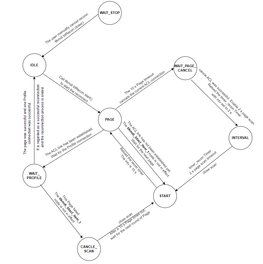
API Description
bool tlkmdi_btRecon_isInBusy(void);
This function checks whether the reconnection is busy via sTlkMdiBtReconCtrl.state. It returns true if reconnection is in progress and false otherwise.
uint8_t tlkmdi_get_btRecon_state(void);
This function obtains the flow state of the callback state machine via sTlkMdiBtReconCtrl.state.
int tlkmdi_btRecon_start(uint8_t *pPageAddr, uint32_t devClass, uint8_t retry_num);
This is the core function of the reconnection management module and is called directly by the application layer. It starts the reconnection management timer and reconnection state machine, and sends a HCI_Create_ConnectionHCI command to the BT controller.
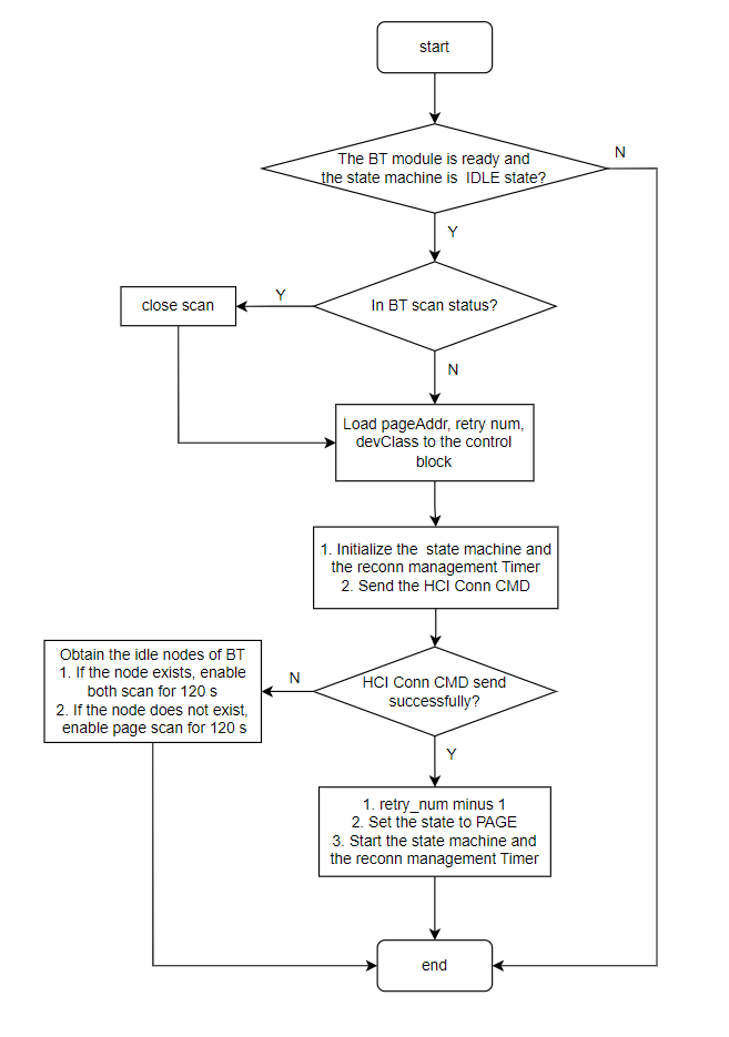
Special Note: This function is non-thread-safe and cannot be called from interrupts. In an RTOS environment, if this interface is called from other non-thread tasks such as audio, system, or user, it must be sent to the host thread via a message queue to ensure secure execution.
uint8_t *tlkmdi_btRecon_getPageAddr(void);
This function is used to obtain the Bluetooth address of the currently reconnected device. If called in a non-reconnected state, the interface is called to get the address NULL.
int tlkmdi_btRecon_close(void);
This function terminates the reconnection process. After being called, it cancels the current Page procedure, stops both the reconnection state machine timer and the reconnection management timer, and restores the tlkmdi_btrecon_t control block to its initial state.
uint8_t tlkmdi_bt_recon_getRemindRetryNum(void);
This function retrieves the current number of remaining reconnection retries.
Inquiry Search
Inquiry is the core mechanism of the traditional Bluetooth (BR/EDR) device discovery phase. Its function is to enable the inquirer to actively scan nearby Bluetooth devices in Discoverable Mode and obtain basic information about these devices (such as device address, device type, clock offset, etc.), laying the foundation for subsequent pairing and connection.
- Device discovery: This is the first step for Bluetooth devices to establish a connection. For example, the process of searching for Bluetooth headsets, speakers, wristbands, and other peripherals on your phone is essentially initiating an inquiry process.
- Information collection: During the inquiry process, the detected device broadcasts key parameters such as its Bluetooth device address (BD_ADDR), device category (CoD), clock offset, etc., to help the initiator identify the device type and prepare for subsequent connections.
Inquiry internal processing logic flowchart:
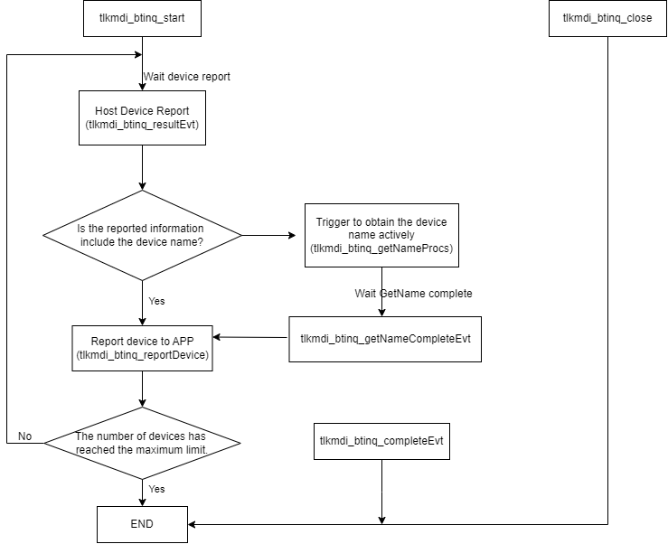
The core processing logic of Inquiry in the SDK is managed by TLK_MW_BTINQ_ENABLE in tlkmdi_btinq.c and tlkmdi_btinq.h, with the following core control block structure:
typedef struct
{
    4uint8_t state;      //The current inquiry status refers to TLKMDI_BTINQ_STATE_ENUM, internal module parameters
    uint8_t busys;      //Check whether the current inquiry is in the busy state, internal parameters of the modules
    uint8_t stage;      //The current inquiry stage refers to TLKMDI_BTINQ_STAGE_ENUM and internal module parameters
    uint8_t inqType;    //The type of device searched by the user refers to BTH_DEVICE_DTYPE_ENUM, and the module internally filters and reports devices based on this parameter
    uint8_t curNumb;    //The device index currently being processed, internal parameters of the modules
    uint8_t maxNumb;    //The maximum number of devices a user can search for is internally limited by the SDK to no more than TLKMDI_BTINQ_ITEM_NUMB
    uint8_t nameIdx;    //Index of device name currently being processed, internal parameters of the modules
    uint8_t rssiThd;   // The RSSI threshold entered by the user is filtered and reported internally by the module based on this parameter
    uint16_t inqWind;   //Inquiry window entered by the user
    uint16_t timeout;   //Timeout time for an inquiry submitted by the user
    TlkApiTimer_t      timer; //Timer tasks
    tlkmdi_btinq_item_t item[TLKMDI_BTINQ_ITEM_NUMB]; //Device information caching
} tlkmdi_btinq_ctrl_t;
typedef struct
{
    uint8_t rssi;     //RSSI of the device
    uint8_t state;    //Device query status, indicating whether the device name has been retrieved
    uint8_t smode;    //The device's page scan repeats pattern, refer to Page_Scan_Repetition_Mode_X
    uint8_t dtype;
    uint8_t nameLen;  //The length of the device's nameIdx
    uint8_t reserve;  //Reserved fields
    uint8_t btaddr[6]; //The device's Bluetooth address
    uint8_t btname[TLKMDI_BTINQ_NAME_LENS + 1]; //The name of the device
    uint16_t reserve2B; //Reserved fields
    uint16_t clkOff;  //Device clock offset
    uint32_t devClass;  //Equipment category
} tlkmdi_btinq_item_t;
The initialization of the Inquiry module and the registration of related HOST events are as follows:
int tlkmdi_btinq_init(void)
{
    STATIC_ASSERT_THIS_FILE(IS_4BYTE_ALIGN(sizeof(tlkmdi_btinq_ctrl_t)));
    memset(&stlk_inq_ctrl, 0, sizeof(tlkmdi_btinq_ctrl_t));
    sTlkmdiBtInqReportCB   = NULL;
    sTlkmdiBtInqCompleteCB = NULL;
    tlksys_timer_createStatic(TLKSYS_TASKID_HOST, &stlk_inq_ctrl.timer, TLKMDI_BTINQ_TIMEOUT, false, tlkmdi_btinq_timer, NULL);
    return TLK_ENONE;
}
BTH_EVT_REGISTER (BTH_EVTID_INQUIRY_RESULT,     tlkmdi_btinq_resultEvt);
BTH_EVT_REGISTER (BTH_EVTID_INQUIRY_COMPLETE,   tlkmdi_btinq_completeEvt);
BTH_EVT_REGISTER (BTH_EVTID_GETNAME_COMPLETE,   tlkmdi_btinq_getNameCompleteEvt);
The key functions the inquiry module provides users with are as follows:
Inquiry launch function:
int tlkmdi_btinq_start(uint8_t inqType,
                       uint8_t rssiThd,
                       uint8_t maxNumb,
                       uint8_t inqWind)
{
    if (stlk_inq_ctrl.state != TLKMDI_BTINQ_STATE_IDLE) {
        return -TLK_EBUSY;
    }
    if (inqWind < 3) {
        inqWind = 3;
    } else if (inqWind > 60) {
        inqWind = 60;
    }
    if (inqWind > 100) {
        inqWind = 100;
    }
    if (maxNumb > TLKMDI_BTINQ_ITEM_NUMB) {
        maxNumb = TLKMDI_BTINQ_ITEM_NUMB;
    }
    if (maxNumb == 0) {
        maxNumb = TLKMDI_BTINQ_ITEM_NUMB;
    }
    stlk_inq_ctrl.inqType = inqType;
    stlk_inq_ctrl.curNumb = 0;
    stlk_inq_ctrl.nameIdx = 0;
    stlk_inq_ctrl.inqWind = ((uint32_t)inqWind * 1000) / TLKMDI_BTINQ_TIMEOUT_MS;
    stlk_inq_ctrl.maxNumb = maxNumb;
    stlk_inq_ctrl.rssiThd = rssiThd;
    stlk_inq_ctrl.state = TLKMDI_BTINQ_STATE_INQUIRY;
    stlk_inq_ctrl.stage = TLKMDI_BTINQ_INQUIRY_STAGE_START;
    tlkapi_trace(TLKMDI_BTINQ_DBG_FLAG, TLKMDI_BTINQ_DBG_SIGN, "tlkmdi_btinq_start type[%d]...", stlk_inq_ctrl.inqType);
    tlksys_timer_reStart(TLKSYS_TASKID_HOST, &stlk_inq_ctrl.timer);
    return TLK_ENONE;
}
Inquiry end function:
void tlkmdi_btinq_close(void)
{
    uint8_t stage;
    if (stlk_inq_ctrl.state == TLKMDI_BTINQ_STATE_IDLE) {
        return;
    }
    if (stlk_inq_ctrl.state == TLKMDI_BTINQ_STATE_CLOSING) {
        return;
    }
    stage = TLKMDI_BTINQ_CLOSING_STAGE_INQUIRY_OVER;
    if (stlk_inq_ctrl.state == TLKMDI_BTINQ_STATE_INQUIRY) {
        if (stlk_inq_ctrl.stage != TLKMDI_BTINQ_INQUIRY_STAGE_WAIT_CANCEL) {
            stage = TLKMDI_BTINQ_CLOSING_STAGE_CANCEL_INQUIRY;
        } else {
            stage = TLKMDI_BTINQ_CLOSING_STAGE_INQUIRY_OVER;
        }
    }
    stlk_inq_ctrl.state = TLKMDI_BTINQ_STATE_CLOSING;
    stlk_inq_ctrl.stage = stage;
    stlk_inq_ctrl.timeout = TLKMDI_BTINQ_WAIT_CANCEL_TIMEOUT;
}
Device reporting interface registration:
void tlkmdi_btinq_regCallback(TlkMdiBtInqReportCallBack reportCB, TlkMdiBtInqCompleteCallBack completeCB)
{
    sTlkmdiBtInqReportCB   = reportCB;  Device reporting interface registration
    sTlkmdiBtInqCompleteCB = completeCB;  Device interface registration is complete
}
Service Inquiries
SDP (Service Discovery Protocol) is one of the core protocols of the traditional Bluetooth (BR/EDR) architecture, and is also the key process for Bluetooth devices to locate and obtain available service information after device discovery. Its core objective is to allow a Bluetooth device (e.g., a mobile phone) to discover the supported service types of a peer device (e.g., Bluetooth headset), including A2DP audio transmission, HFP call, HID keyboard‑mouse control, and their associated protocol parameters (e.g., L2CAP channel ID, RFCOMM port number). This serves as the essential basis for establishing subsequent service connections.
SDP Server: The device providing services (such as Bluetooth headsets), which has a built-in 'service record database' that stores descriptions of all its services;
SDP Client: The device (such as a mobile phone) initiating the query sends a query request to the server and parses the returned service information.
SDP queries communicate using fixed channel (PSM=0x0001) channels based on the L2CAP protocol. Before any formal service connection is established, the client and server can query through this channel. For SDP, the entire query process is divided into four steps:
(1) Establish an SDP session: After the client and server establish a basic Bluetooth connection (L2CAP channel), by default, SDP requests are initiated through a fixed channel with PSM=0x0001 without additional negotiation.
(2) Client sends query requests: The client can initiate two types of core queries:
-
Query by service class UUID: specify the UUID of the target service (such as 0x110B) to check whether the server supports the service and its corresponding parameters;
-
Obtain an overview of all server services (such as service name and type) to traverse all available services on the device.
(3) Server responds with query results: After the server parses the request, it matches eligible services from the local service record database, packages the specified attributes of the service record into an "SDP response packet", and returns it to the client.
(4) Client parsing and connection establishment: Service parameters in client-side parsing responses (such as RFCOMM channel number) initiate specific service connections based on these parameters (e.g., establishing an A2DP audio channel via RFCOMM port). After the SDP session is completed, it can be closed (or reserved for future re-examination).
Currently, the SDK binds the service channels supported by the queried peer device to the device and writes the matching information into Flash. When a device is connected, the SDK will only trigger an SDP query if the valid service channel information of this device is not read. The specific trigger function is as follows:
int btp_sdpclt_connect(uint16_t aclHandle);
The service channel information reporting interface supported by the peer device is as follows:
BTP_EVT_REGISTER (BTP_EVTID_PROFILE_CHANNEL,         tlkmdi_btacl_profileChannelEvt);
static int tlkmdi_btacl_profileChannelEvt(uint8_t *pData, uint16_t dataLen)
{
    (void)dataLen;
    btp_channelEvt_t    *pEvt;
    tlkmdi_btacl_item_t *pItem;
    pEvt  = (btp_channelEvt_t *)pData;
    pItem = tlkmdi_btacl_getUsedItem(pEvt->handle);
    if (pItem == NULL) {
        tlkapi_error(TLKMDI_BTACL_DBG_FLAG, TLKMDI_BTACL_DBG_SIGN, "tlkmdi_btacl_profileChannelEvt: error - no node");
        return TLK_ENONE;
    }
    if (pEvt->service == BTP_SDP_SRVCLASS_ID_HANDSFREE) {
        pItem->hfChannel = pEvt->channel;
    } else if (pEvt->service == BTP_SDP_SRVCLASS_ID_HANDSFREE_AGW) {
        pItem->agChannel = pEvt->channel;
        if (pEvt->channel != 0) {
            if (pItem->active == false) {
                tlkmdi_tinySql_setPairingDeviceRfcChid(pItem->btaddr, pEvt->channel, TLKMDI_BT_RFC_CHID_HFP);
            }
            btp_tws_set_rfcommChnID(pEvt->channel, true);
        }
    } else if (pEvt->service == BTP_SDP_SRVCLASS_ID_SERIAL_PORT) {
        pItem->sppChannel = pEvt->channel;
        if (pEvt->channel != 0) {
            btp_tws_set_rfcommChnID(pEvt->channel, false);
        }
        tlkmdi_tinySql_setPairingDeviceRfcChid(pItem->btaddr, pEvt->channel, TLKMDI_BT_RFC_CHID_SPP);
    } else if (pEvt->service == BTP_SDP_SRVCLASS_ID_IAP2_TEMP) {
        pItem->iapChannel = pEvt->channel;
        tlkmdi_tinySql_setPairingDeviceRfcChid(pItem->btaddr, pEvt->channel, TLKMDI_BT_RFC_CHID_IAP);
    } else if (pEvt->service == BTP_SDP_SRVCLASS_ID_PBAP_PSE) {
        pItem->pbapChannel = pEvt->channel;
        tlkmdi_tinySql_setPairingDeviceRfcChid(pItem->btaddr, pEvt->channel, TLKMDI_BT_RFC_CHID_PBAP);
    } else if (pEvt->service == BTP_SDP_SRVCLASS_ID_IMAGING_RESPONDER) {
        pItem->bipChannel = pEvt->channel;
        tlkmdi_tinySql_setPairingDeviceRfcChid(pItem->btaddr, pEvt->channel, TLKMDI_BT_RFC_CHID_BIP);
    }
    return TLK_ENONE;
}
Protocol Connections
The Bluetooth Profile (protocol subset) is the core protocol specification for implementing specific functions (such as calls and music playback) between classic Bluetooth (BR/EDR) devices. It is based on underlying protocols such as L2CAP and SDP, defining details such as device roles, data interaction flows, and encoding formats. For consumer electronics (such as Bluetooth headsets and speakers), the essence of Profile connection is the complete process of "device role negotiation -> SDP service discovery logical link establishment -> data transmission," with different profiles corresponding to different functional scenarios.
Common profiles include:
- SDP (Service Discovery Protocol): Used for service discovery to determine the profile supported by the device.
- A2DP (Advanced Audio Distribution Profile): Used for transmitting high-quality audio streams, typically to transfer audio from a phone or computer to Bluetooth headphones or speakers.
- AVRCP (Audio/Video Remote Control Profile): Allows users to control playback of audio and video devices, such as volume adjustment, play/pause, etc.
- HFP (Hands-Free Profile): Allows hands-free devices to communicate with mobile phones, commonly used in in-car hands-free systems.
- HID (Human Interface Device): Human-machine interface devices, such as mice, keyboards, controllers, game controllers, etc.
- SPP (Serial Port Profile): The Serial Port Protocol is a special profile; it is a connectionless profile used to achieve serial port communication.
When using the relevant profile, you first need to enable the profile's functions before performing related operations.
//BT Stack Configuration//
#define TLK_STK_BT_ENABLE         1
#define TLKBTP_CFG_RFC_ENABLE     (1 && TLK_STK_BT_ENABLE)
#define TLKBTP_CFG_SPP_ENABLE     (1 && TLKBTP_CFG_RFC_ENABLE)
#define TLKBTP_CFG_HFP_ENABLE     (1 && TLKBTP_CFG_RFC_ENABLE)
#define TLKBTP_CFG_HFPHF_ENABLE   (1 && TLKBTP_CFG_HFP_ENABLE)
#define TLKBTP_CFG_A2DP_ENABLE    (1 && TLK_STK_BT_ENABLE)
#define TLKBTP_CFG_A2DPSNK_ENABLE (1 && TLKBTP_CFG_A2DP_ENABLE)
General connection process:
- Discovery and Pairing: inquiry/page discovers devices, completes pairing, authentication, and encryption, generates and saves Link_Key, and establishes ACL links.
- SDP Query: The client sends an SDP query to the server to confirm whether it supports the target profile (such as A2DP Sink), obtaining key parameters such as PSM, service UUID, and channel information.
- L2CAP channel establishment: The client initiates an L2CAP connection request based on PSM and negotiates MTU and flow control parameters; The server passively responds and allocates the CID. Once the channel is ready, it enters data transfer preparation.
- Profile Specific Negotiation: Complete capability negotiation according to Profile specifications, such as A2DP negotiation encoding format (SBC/AAC/LDAC); HFP negotiates AT instruction sets with SCO/eSCO link parameters.
- Data transmission and control: A2DP transmits audio streams via L2CAP; HFP transmits voice via SCO/eSCO, while simultaneously sending AT instructions via L2CAP; AVRCP sends control commands and receives status feedback.
- Disconnection: The client can proactively disconnect the L2CAP channel, or the server may proactively reject/close it. After disconnecting, release CID, PSM, and related resources.
Bluetooth Profile defines both Client and Server. The Client device initiates Profile function requests, while the Server device responds and provides services.
In the SDK, after the Bluetooth encryption process is completed, the profile connection is performed. First, it checks the current connected device's address to see if there is a connection record with that device. If there is a record, it connects directly and is called at this point.
void app_btmgr_appendProfile(uint16 aclHandle);
This function adds the profiles to be connected to the connection manager queue and creates connections in sequence. By default, it creates profiles such as RFCOMM, HFP, A2DP, AVRCP, etc.
If there are no records, the btp_sdpclt_connect is called to query the profiles supported by the peer device:
int btp_sdpclt_connect(uint16 aclHandle);
This function creates an SDP connection as a client.
The determination process in the SDK is as follows:
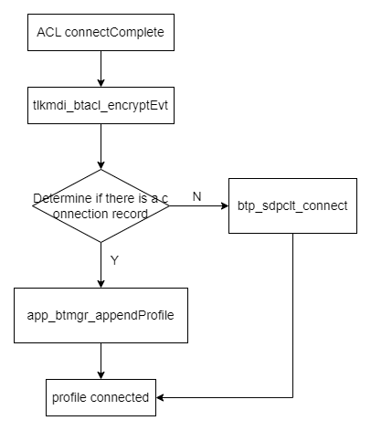
To obtain the connection status of the profile, you need to register the event callback function for the profile state:
BTP_EVT_REGISTER (BTP_EVTID_PROFILE_CONNECT,         tlkmdi_btacl_profileConnectEvt);
tlkmdi_btacl_regProfileConnectCB(app_btmgr_ProfConnCB);
This function is called when the profile connection succeeds or fails.
When the profile is disconnected, a corresponding event notification will be given, and the application layer needs to register the corresponding event callback function:
BTP_EVT_REGISTER (BTP_EVTID_PROFILE_DISCONN,         tlkmdi_btacl_profileDisconnEvt);
tlkmdi_btacl_regProfileDisconnCB(app_btmgr_ProfDiscCB);
profile connection:
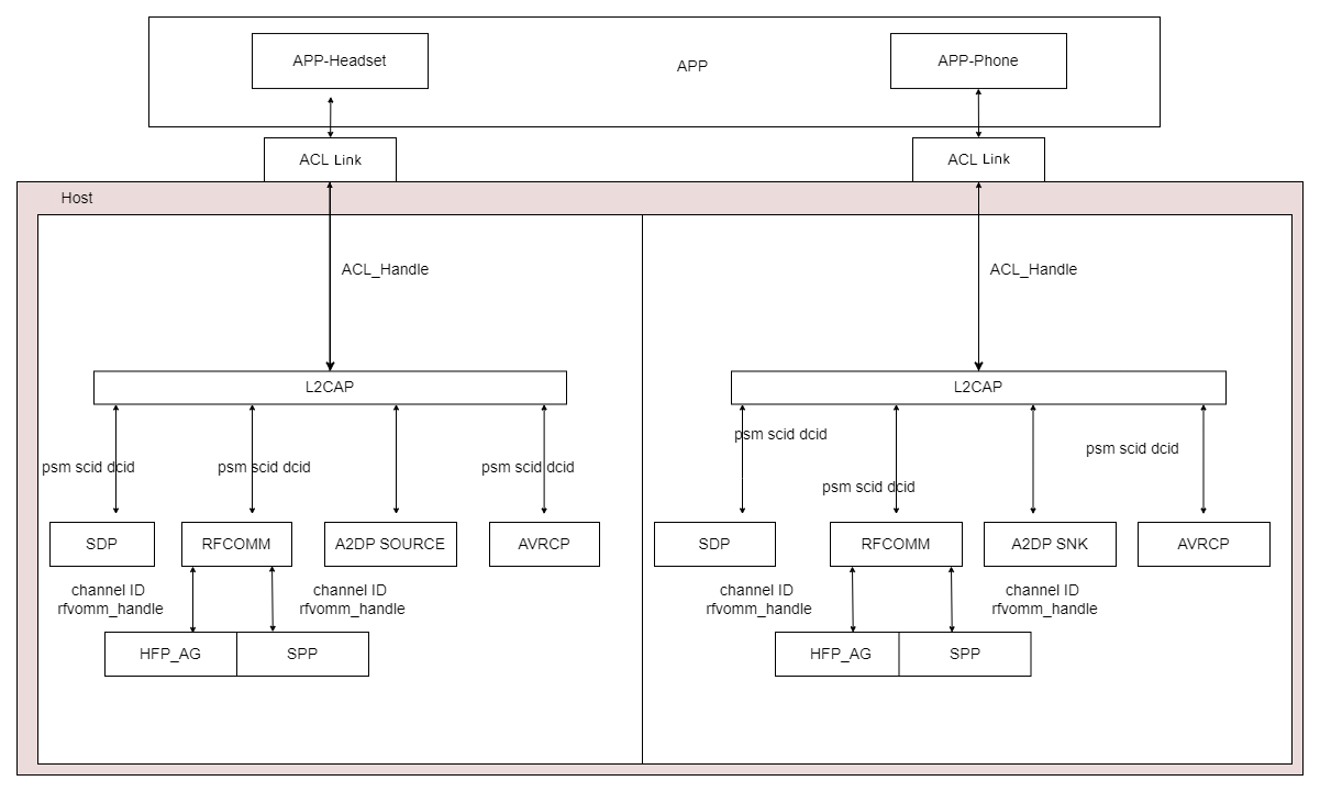
- L2CAP connection
All host protocol connections are based on L2CAP, and Setup has four processes:
Connection_Request\Connection_ResponseConfigure_Request\Configure_ResponseConfigure_Request\Configure_ResponseConfigure_Request\Configure_Response
The initiators are different. The first was initiated by Central, the second by Peripheral. Ultimately, a Source CID and a Destination CID are generated to identify the current pathway.
- SDP service inquiry
SDP service query to determine which application protocols the peer device supports. Before querying the SDP service, establish an L2CAP link, then send query commands to the other party, wait for the results, parse and upload, and release the L2CAP link after the query is complete. After the query is complete, once the supported service types are known, the connection can be created as needed. For example, the phone knows that the headphones support protocols such as HFP, A2DP, AVRCP, etc.
- HFP connection
HFP is based on RFCOMM connections, and the phone's audio connection can be initiated on both the AG and HF sides. The message exchange and flow during the connection process are generally the same, as shown in the figure below.
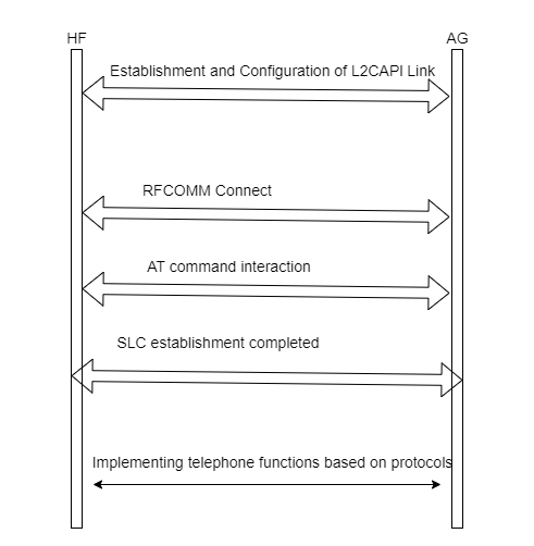
The AT instruction interactions involved are as follows:
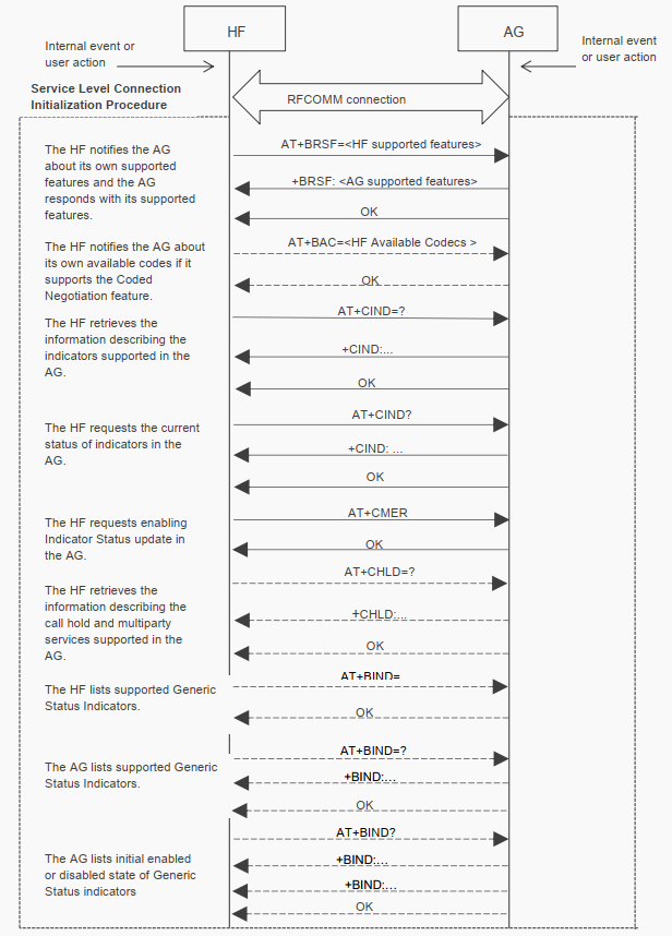
For detailed instructions, please refer to HFP.
- A2DP connection
A2DP is based on AVDTP connections. During the A2DP connection process, two types of channels are created: the Signaling Channel and the Media Transport Channel. The former is used for sending commands, while the latter is used for transmitting audio data. On the Signaling Channel.
Once the channel is established, some parameters are negotiated, such as encoding format, sampling rate, number of data transmission channels, and priority of data transmission channels. The general parameter negotiation process is shown in the diagram below.
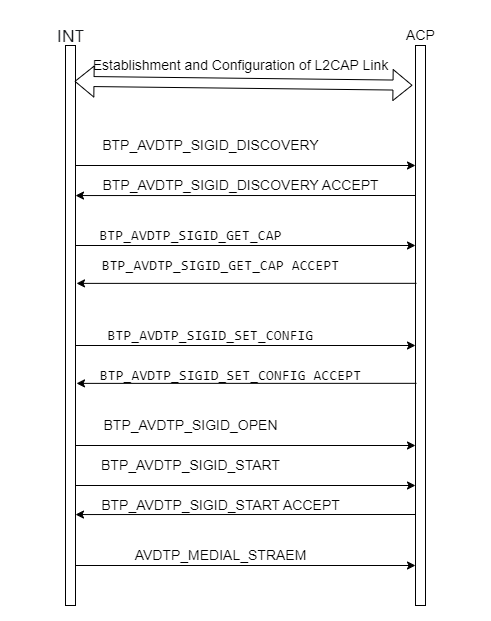
Call Management
In the SDK, devices can connect to both headphones and phones. For the HFP profile, when connecting headphones, the device acts as the AG role, and when connecting to the phone, it acts as the HF role.
(1) Call control
Call control includes functions such as answering, hanging up, and rejecting calls. Incoming call answering, hanging up, and rejecting calls can be controlled through the following interfaces:
int tlkapp_audio_callCtrl(uint8_t opcode)
{
    bool res = false;
    if(opcode != TLKAUD_OPCODE_CALL_ACCEPT && opcode != TLKAUD_OPCODE_CALL_HUNGUP){
        return -TLK_EPARAM;
    }

    const tlkapp_audioScheduler_node_t *nowTask = tlkapp_audioScheduler_getRunningTask();
    if (nowTask != nullptr) {
        res = tlkapp_audio_modinfOperate((uint16)nowTask->taskId, (uint16)nowTask->info.optype, &opcode, 1);
    }
    if (res == false) {
        uint16 msgID = opcode == TLKAUD_OPCODE_CALL_ACCEPT ? TLKSYS_BT_MSGID_HF_SEND_CALL_ACCEPT : TLKSYS_BT_MSGID_HF_SEND_CALL_HUNGUP;
        uint16 handle = 0xFFFF;
        return tlksys_sendMsg(TLKSYS_TASKID_HOST, msgID, &handle, 2);
    }
    return TLK_ENONE;
}
When the call status changes, AG notifies the current state via +CIEV. When HF receives the +CIEV instruction, the HF side calls the btp_hfphf_recvCievCmdHandler() function for data parsing, mainly involving the call and callsetup two states of change.
call: Standard call status indicator, where:
- <value>=0 means there are no ongoing calls
- <value>=1 means at least one call is in progress
callsetup: calls the establishment status indicator, where:
- <value>=0 means it is not currently in the call settings
- <value>=1 means incoming call processing is ongoing
- <value>=2 means outgoing call settings are underway
- <value>=3 means the remote party receives an alert during the outgoing call.
Answer the phone:
When answering a call, it checks the current call status, checks the status of call and callsetup, and if call=1 and callsetup=1, it calls btp_hfphf_answer and sends the ATA\r command to reply to AG.
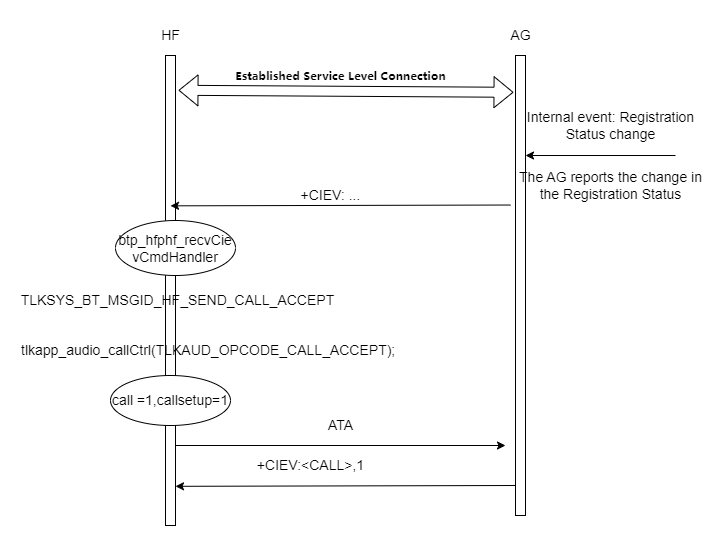
Refusing to answer/hang up the phone:
When rejecting or hanging up a call, the current call status is checked, and the status of call and callsetup is checked. If call=1 and callsetup=1, it will call btp_hfphf_reject and send the AT+CHUP instruction to reply to AG.
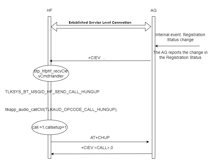
/* Send the corresponding event message */
tlksys_sendMsg(TLKSYS_TASKID_HOST, TLKSYS_BT_MSGID_HF_SEND_CALL_ACCEPT, &handle, sizeof(handle));
/* Answer */
tlkapp_audio_callCtrl(TLKAUD_OPCODE_CALL_ACCEPT);
/* Send the corresponding event message */
tlksys_sendMsg(TLKSYS_TASKID_HOST, TLKSYS_BT_MSGID_HF_SEND_CALL_HUNGUP, &handle, sizeof(handle));
/* Reject */
tlkapp_audio_callCtrl(TLKAUD_OPCODE_CALL_HUNGUP);
(2) Call volume control
Call volume control consists of volume settings and volume change notifications.
Volume settings:
Volume setting generally refers to the device setting the volume. After receiving the command to set the volume, the phone adjusts the volume based on the set value. After the key event is triggered, the tlkapp_btmgr_setHfpVolumeDeal() function is called, which sends the volume level to be set to the phone (AT+VGS command).
int tlkapp_btmgr_setHfpVolumeDeal(uint8_t *pData, uint8_t dataLen);
int btp_hfphf_setSpkVolume(uint08 spkVolume);
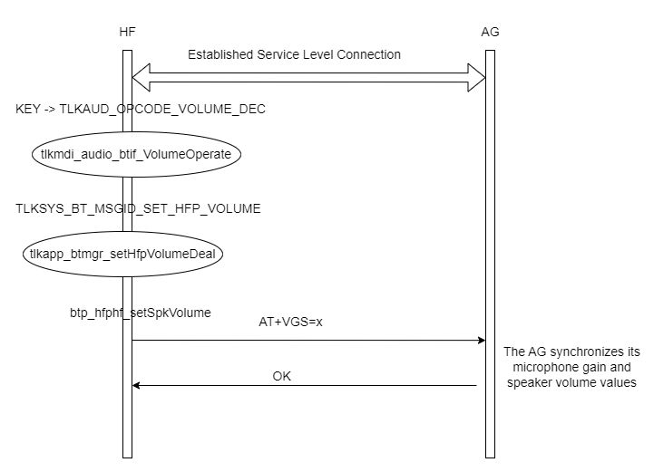
Volume notifications:
When the phone adjusts the volume, the volume change is synchronized to the earbuds. When the volume changes on the phone, the device receives a +VGS message, which notifies the application layer of the volume change, which takes effect in real time when the codec is running.
int btp_send_hfphfVolumeChangedEvt(uint16 aclHandle, uint08 type, uint08 volume)
{
    btp_hfpVolumeChangedEvt_t evt;
    evt.handle  = aclHandle;
    evt.volume  = volume;
    evt.volType = type;
    return btp_send_event(BTP_EVTID_HFPHF_VOLUME_CHANGED, (uint08 *)&evt, sizeof(btp_hfpVolumeChangedEvt_t));
}
To promptly respond to volume changes, the application layer needs to register a callback function for volume change events:
BTP_EVT_REGISTER (BTP_EVTID_HFPHF_VOLUME_CHANGED, tlkmdi_hfphf_volumeChangedEvt);
The tlkmdi_hfphf_volumeChangedEvt() function is called upon receiving a volume change message, and then notifies the application layer of the volume change in the form of an event for corresponding processing.
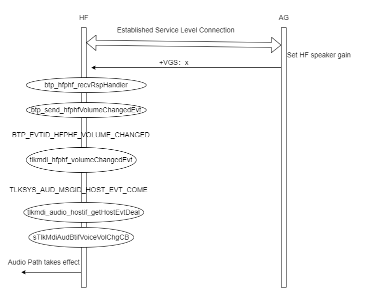
(3) Call trigger
Both HF and AG can act as initiators for calls, but Codec Connection Setup is initiated by AG, with HF as the connected party.
- When triggering a call as an AG, the following interfaces can be called:
/******************************************************************************
 * Function: tlkmdi_bthfpag_createSco
 * Descript: Create a one-way SCO connection via AG.
 * Params:
 *        @pBtAddr[IN]--The device address.
 * Return: Returning TLK_ENONE(0x00) means the send process success.
 *         If any other value is returned, it means the send process failed.
 *******************************************************************************/
int tlkmdi_bthfpag_createSco(uint08 *pBtAddr);
Since the address of the connected device needs to be passed, the device address must be obtained first. The address of the connected device can be obtained through the following interfaces:
uint08 *bth_handle_getBtAddr(uint16 aclHandle);
uint16 btp_hfp_getAgHandle(void);
Once the device address is obtained, you can call the tlkmdi_bthfpag_createSco() interface to create an SCO connection.
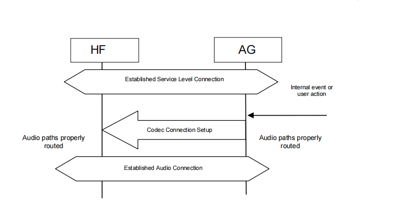
- When triggering a call as an HF character, you can call the following interface:
/******************************************************************************
 * Function: btp_hfphf_codecConn
 * Descript: Used by the HF to request the AG to start the codec connection procedure.
 * Params:
 *        @aclHandle[IN]--The acl handle.
 * Return: Returning TLK_ENONE(0x00) means the send process success.
 *         If any other value is returned, it means the send process failed.
 *******************************************************************************/
int btp_hfphf_codecConn(uint16_t aclHandle);
The HF role actually triggers a call by sending the AT+BCC command to AG. After AG receives the instruction, it replies OK and then initiates the Codec Connection Setup related command.
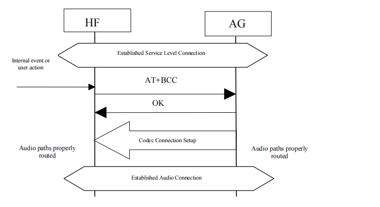
(4) Siri
Siri is Apple's smart voice assistant, mainly integrated into Apple's ecosystem including iOS, iPadOS, macOS, and watchOS. Its core function is to help users perform various operations through natural language interaction, and in embedded scenarios, it also deeply integrates with hardware such as iPhone microphones and Bluetooth devices.
At the user level, Siri is triggered and shut down through the following interfaces:
int tlkmdi_bthfphf_assistant(uint16 handle);
The execution flow of the function is tlkmdi_bthfphf_assistant()->btp_hfphf_siri_ctrl()->btp_hfphf_sendIphoneSiriCtrlProc(). Essentially, Siri's trigger and shutdown are an interaction of AT commands (AT+BVRA=1 triggers Siri, AT+BVRA=0 disables Siri).
Music Management
(1) Volume control
Volume control is divided into volume settings and volume change notifications.
Volume notifications:
To know how your phone's volume changes, you need to register a callback function for the volume change event.
BTP_EVT_REGISTER (BTP_EVTID_AVRCP_VOLUME_CHANGED, tlkmdi_btavrcp_volumeChangeEvt);
tlkmdi_btavrcp_volumeChangeEvt is called when the phone's volume changes, passing the changed volume value and the connected handle parameter into the function. Then, the volume change is notified to the application layer through events:
tlksys_sendMsg(TLKSYS_TASKID_AUDIO, TLKSYS_AUD_MSGID_HOST_EVT_COME, buffer, bufferLen);
After receiving the TLKSYS_AUD_MSGID_HOST_EVT_COME event, the application layer calls the following functions to handle the corresponding event:
int tlkmdi_audio_hostif_getHostEvtDeal(uint8_t *pData, uint8_t dataLen)
void tlkmdi_audio_btif_getHostEvtDeal(uint8_t *pData, uint8_t dataLen)
In the tlkmdi_audio_btif_getHostEvtDeal function, call the corresponding handler functions according to the event type.
void tlkmdi_audio_btif_getHostEvtDeal(uint8_t *pData, uint8_t dataLen)
{
if(dataLen < sizeof(tlksys_msg_hostEvt_t)){
return;
}
tlksys_msg_hostEvt_t * evt = (tlksys_msg_hostEvt_t *)pData;
if(evt->hostType != TLKSYS_MSG_HOST_TYPE_BT){
return;
}
switch(evt->msgID){
case TLKSYS_MSG_BT_HOST_EVT_TYPE_VOLUME_CHG:{
if(evt->dataLen != sizeof(tlksys_msg_hostEvt_btVolChg_t)){
return;
}
tlkmdi_audio_btif_getVolumeChgDeal((tlksys_msg_hostEvt_btVolChg_t *) evt->data);
}break;
case TLKSYS_MSG_BT_HOST_EVT_TYPE_AUD_STATE_CHG:{
if(evt->dataLen != sizeof(tlksys_msg_hostEvt_btAudStateChg_t)){
return;
}
tlkmdi_audio_btif_getAudStateChgDeal((tlksys_msg_hostEvt_btAudStateChg_t *) evt->data);
}break;
}
}
typedef enum
{
TLKSYS_MSG_BT_HOST_EVT_TYPE_VOLUME_CHG = 0x00,
TLKSYS_MSG_BT_HOST_EVT_TYPE_AUD_STATE_CHG,
} TLKSYS_MSG_BT_HOST_EVT_TYPE_ENUM;
| Field | Description |
|---|---|
| TLKSYS_MSG_BT_HOST_EVT_TYPE_VOLUME_CHG | This event is reported to the upper layer when the phone volume changes. |
| TLKSYS_MSG_BT_HOST_EVT_TYPE_AUD_STATE_CHG | This event is reported to the upper layer when the music playback state changes. |
The upper layer needs to register the event callback function for volume changes:
void tlkmdi_audio_btif_regMusicVolChgCB(TlkMdiAudBtifVolChgCB cb)
Volume settings:
Volume control generally refers to setting the volume on the device side. After receiving the command to set the volume, the phone adjusts the volume according to the set value.
Volume adjustment on the device is triggered by buttons, so you need to configure the volume adjustment event in the button event settings. In the SDK, volume adjustment settings are set in sApp_key_default_config. Ultimately, the Audio task calls the function int tlkapp_audio_msgHandle() that receives messages to handle the event.
int tlkapp_audio_msgHandle(uint8_t msgID, uint8_t *pData, uint16 dataLen);
int tlkapp_audio_volumeCtrl(uint8_t isInc);
The tlkapp_audio_volumeCtrl() function determines whether to increase or decrease the volume based on the isInc parameter, then calls the corresponding Audio task interface to set the volume. Ultimately, volume setting commands are sent to the phone via the BTP protocol.
tlksys_sendMsg(TLKSYS_TASKID_HOST, TLKSYS_BT_MSGID_SET_AVRCP_VOLUME, buffer, buffLen);
int tlkapp_btmgr_setAvrcpVolumeDeal(uint08 *pData, uint08 dataLen);
The overall flow of volume control is as follows:
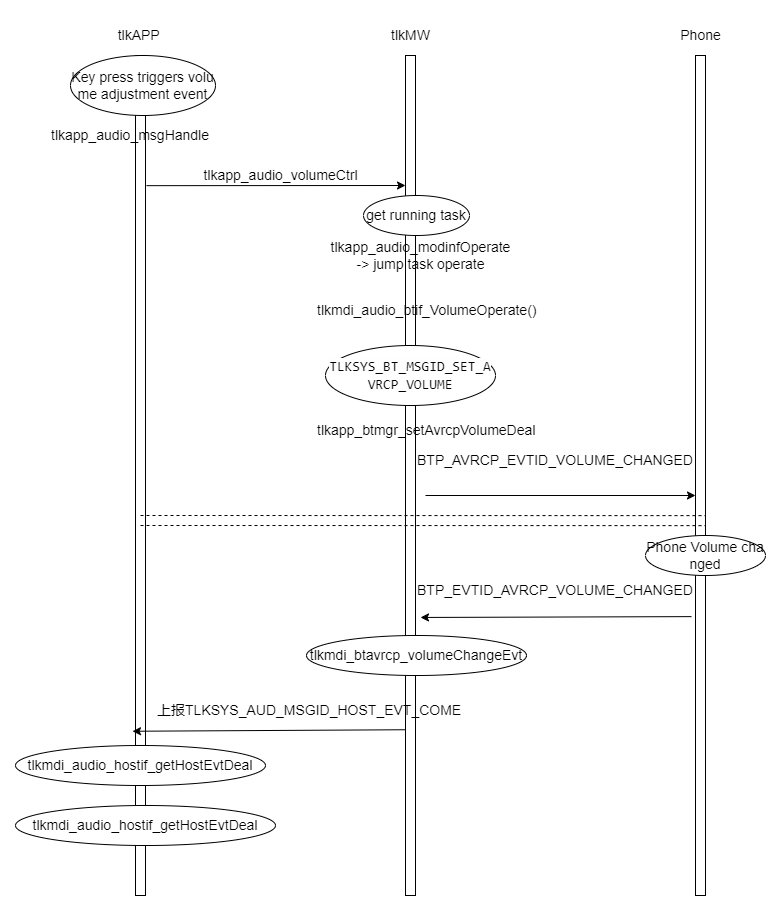
(2) Playback status control
To know the music playback status on the phone, you need to register the event callback function for the music playback status.
BTP_EVT_REGISTER (BTP_EVTID_A2DPSNK_STATUS_CHANGED, tlkmdi_bta2dp_statusChgCB);
BTP_EVT_REGISTER (BTP_EVTID_AVRCP_STATUS_CHANGED, tlkmdi_btavrcp_statusChgCB);
-
The
tlkmdi_bta2dp_statusChgCB()function is called when the A2DP playback state changes. -
The
tlkmdi_btavrcp_statusChgCB()function is called when the AVRCP playback state changes.
When the music playback status on the phone changes, the corresponding event callback function is called, and then tlkmdi_bta2dp_sendHostMusicStateChgEvt() is called to notify the application layer.
The changes in the state of music over different periods are as follows:
| Trigger events | A2DP status changes | AVRCP status changes |
|---|---|---|
| The phone initiates the "Play" command | IDLE -> STREAMING | STOPPED/PAUSED -> PLAYING |
| The phone initiates a "pause" command | STREAMING -> SUSPENDED | PLAYING -> PAUSED |
| Headphones actively "switch tracks" | Maintaining STREAMING (New Audio Stream) | PLAYING -> PLAYING (New Track) |
| Bluetooth disconnects | Any state -> DISCONNECTED | Any state -> DISCONNECTED |
| Audio playback complete | STREAMING -> IDLE | PLAYING -> STOPPED |
The application layer controls the relevant actions of the codec by executing the following interfaces:
void tlkmdi_bta2dp_sendHostMusicStateChgEvt(uint16 handle,uint08 state);
void tlkmdi_audio_btif_getHostEvtDeal(uint8_t *pData, uint8_t dataLen);
static void tlkmdi_audio_btif_getAudStateChgDeal(tlksys_msg_hostEvt_btAudStateChg_t *evt)
Taking music playback as an example, when acting as an SNK, after receiving the SRC control command, the SNK's response process is as follows: the response to pause and upper and lower track commands is consistent with the start command, only the SNK response data differs.

Whether it's volume control or state control, the following functions are called to handle them. These functions will distribute the corresponding event to the corresponding processing function based on the current business scenario:
bool tlkapp_audio_modinfOperate(uint16 handle, TLKAUD_TYPE_ENUM optype, uint8_t *pData, uint16 dataLen)
(3) Multimedia UI
In music scenes, the application-layer UI involves playing, pausing, moving to the next track, and the previous track. The following interfaces are commonly used to implement this:
int tlkapp_audio_PlayPause(void);
bool tlkapp_audio_playNext(void);
bool tlkapp_audio_playPrev(void);
int tlkapp_audio_volumeCtrl(uint8_t isInc);
When controlling multimedia, it is essentially sending instructions to the counterpart device, which parses the command and executes the corresponding operation. These instructions depend on specific protocols.
Taking the SNK side as an example of triggering music playback, the process from key trigger to sending the corresponding command is as follows:
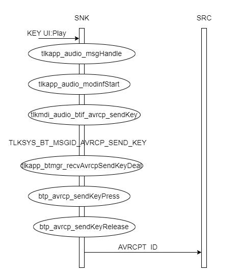
At the SNK end, the process for triggering playback, pause, next track, and previous song is the same, except the commands sent are different. The following instructions are to be sent via the AVRCP protocol:
AUD_BTIF_AVRCP_KEYID_PLAY = 0x44,
AUD_BTIF_AVRCP_KEYID_STOP = 0x45,
AUD_BTIF_AVRCP_KEYID_PAUSE = 0x46,
AUD_BTIF_AVRCP_KEYID_RECORD = 0x47,
AUD_BTIF_AVRCP_KEYID_REWIND = 0x48,
BLE Related
BLE Host architecture
BLE Host, or Bluetooth Low Energy Host, is the upper core component of the Bluetooth Low Energy protocol stack. It plays a key role in protocol logic control, application interaction integration, and data scheduling management within the entire Bluetooth communication architecture. It interfaces downward to the BLE Controller and provides standardized communication interfaces for various applications upward, serving as the core hub for stable and efficient communication between Bluetooth Low Energy devices.
In terms of specific features, BLE Host's core capabilities are mainly reflected in the following aspects:
Link layer and connection management: Responsible for pairing, binding, and establishing connections for Bluetooth devices, including device discovery, connection parameter negotiation, connection maintenance and disconnection, and other processes. Key parameters like connection spacing and timeout can be adjusted according to application needs, optimizing power consumption while ensuring communication stability.
Protocol layer specification execution: Supports and runs the upper-layer protocols of the Bluetooth Low Energy protocol stack, such as the Universal Attribute Protocol (GATT), General Access Protocol (GAP), and Security Management Protocol (SM). Among them, GATT defines the attribute structure and interaction methods for data transmission, enabling devices to clearly recognize and read and write feature data between devices; GAP regulates device role behaviors, such as broadcaster, observer, master device, and mode switching of slave devices; SM is responsible for encryption and authentication during the pairing process, ensuring the security of communication data.
Data Interaction and Business Adaptation: As an intermediate bridge between applications and underlying hardware, BLE Host receives instructions and data from the application layer, encapsulates them as data packets compliant with Bluetooth protocol specifications, and then sends them to the end-to-end device via the controller; At the same time, it parses peer data packets received from the controller, extracts valid information, and passes it upward to the application layer, enabling bidirectional business data flow.
Multi-Device and Multi-Link Coordination: Supports simultaneous management of multiple Bluetooth connection links, coordinates communication resource allocation between different devices, and avoids data transmission conflicts. This is especially suitable for scenarios where gateway devices connect multiple slave devices simultaneously, ensuring orderly multi-device communication.
This SDK offers a wide variety of BLE Application scenarios. Traditional BLE devices, BLE HID Host, BLE Audio, etc., all need to be developed based on the Host architecture, with single-core and multi-core chips required for adaptation. To simplify the later development logic, it is very necessary to redesign the architecture of the Host.
The new BLE Host architecture is shown in the diagram below, divided into three layers by code layer: Software Abstraction Layer (SAL), HCI Interface Layer (HIL), and Protocol Stack Layer (PSL).
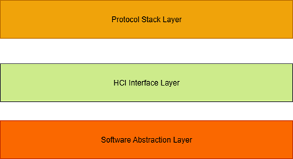
According to functional modules, BLE Host is divided into the following modules:
Software Abstraction Layer(SAL): The software abstraction layer is mainly responsible for interacting with the platform and abstracting basic components, such as log printing and NVRAM read/write.
Host Controller Interface(HCI): The HCI interface is mainly responsible for interacting with the HCI protocol stack, including sending HCI commands, handling events, receiving ACL data, sending ACL data, receiving ISO data, and sending ISO data.
Generic Access Profile(GAP): The General Access Protocol layer is mainly responsible for encapsulating HCI commands, including device discovery, connection parameter negotiation, connection establishment, and connection disconnection.
Logical Link Control and Adaptation Protocol(L2CAP): The L2CAP protocol layer is mainly responsible for managing the logical channels of connections, including channel establishment, channel release, and channel data transmission.
Generic Attribute Profile(GATT): The General Attribute Protocol layer is mainly responsible for managing the device's services, features, descriptors, etc., including service discovery, feature discovery, feature read/write, etc.
Services: The service layer is mainly responsible for implementing GATT services, including general services and custom services.
Profiles: The Profile layer is mainly responsible for implementing GATT Profiles, including general profiles and custom profiles.
ISO data: The ISO data layer is mainly responsible for implementing data flow control and distribution under ISO data protocols.
Host Management: The host management layer is mainly responsible for managing general host information, such as controller chip information, version information, system information, and ACL connection quantity management.
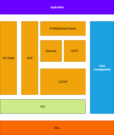
BLE GAP
In this BLE Host design, the GAP module is responsible for encapsulating HCI commands, organizing HCI command streams, handling HCI events, and distributing GAP events.
The modules currently implemented in the GAP SDK include:
- GAP BLE ACL
- GAP BLE Advertising
- GAP Filter
- GAP BLE ISO
- GAP Host Address
- GAP Periodic Advertising
- GAP BLE Scan
- GAP Event Dispatch
The following sections describe the functions of these modules and how to use them.
GAP BLE Advertising module
BLE's broadcast module is divided into two types: legacy advertising and extended advertising. Legacy advertising is the most basic broadcast mode, while extended advertising can carry more broadcast information and supports multiple broadcasts simultaneously. For specific usage, refer to the BLE ADV demo in the examples.
GAP BLE ACL module
BLE connection modules, including creating connections in BLE Central; BLE Peripheral enables Telink Controller's Latency and BLE Peripheral reconnection functions; Functions in BLE ACL include Connection parameter update, Feature exchange, Data Length Update, PHY Update, disconnection, and more. For details, refer to the API interface comments for the GAP ACL module.
GAP Filter module
BLE's filtering module currently only supports the BLE Filter Accept List function, which allows setting different filtering conditions. During the broadcast or connection establishment stages, devices that do not meet the criteria are filtered out.
GAP BLE ISO module
BLE's ISO module: ISO is a new feature added after Core 5.2, currently supporting two major modules: BIG Broadcast, BIG Synchronous, CIS Central, and CIS Peripheral. Usually, users do not call it directly.
GAP Host Address module
BLE host addresses, now supporting Resolvable Private Address, Static Device Address, and Non-resolvable Private Address. For detailed usage, refer to the random address demo in the BLE examples.
GAP Periodic Advertising module
BLE's periodic broadcast module, which includes synchronous and broadcast modes for periodic broadcasts, is usually associated with BIG in the SDK.
GAP BLE Scan module
BLE's scanning module, which includes functions such as starting, stopping, and filtering BLE scans, handles event handling for extended broadcasts and traditional broadcasts in the same way, making it easier for application layer calls. For specific usage, refer to the BLE Scan demo in BLE Examples.
GAP Event Dispatch module
BLE's event distribution module includes the distribution of GAP events, handling GAP events, and handling GAP event callbacks. By registering, event messages can be subscribed to and retrieved, decoupling different modules.
BLE ATT
BLE GATT is the base unit of attributes
GATT defines two roles: Server and Client. A server typically contains multiple sets of services, and clients operate on services through ATT layer commands. A set of services consists of a service UUID and multiple characteristic UUIDs. Each UUID consists of multiple attributes, each containing a certain amount of information used to describe the UUID's information.
Note
- ACL has two roles: central and peripheral, decoupled from the server and client at the GATT layer. ACL Peripheral roles can be either GATT servers or GATT clients, and the same applies to ACL Central roles.
- All APIs introduced later are ACL connection handles, usually without distinguishing between ACL roles. Unless the profile explicitly states that it can only be used under a specific ACL role.
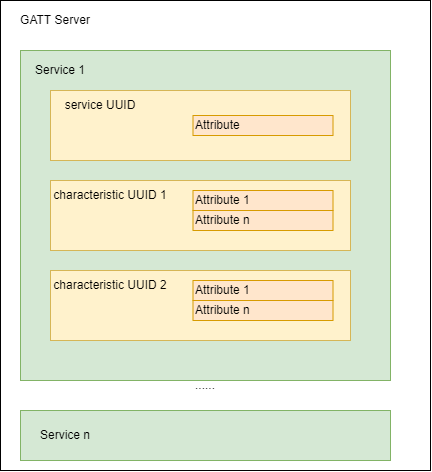
An Attribute section includes the Attribute handle, Attribute Type, Attribute value, and Attribute table.
1) Attribute Type: UUID
UUIDs are used to distinguish the type of each attribute, with a total length of 16 bytes. In the BLE standard protocol, UUID length is defined as 2 bytes, because all devices follow the same conversion method, converting a UUID with 2 bytes into 16 bytes.
When the server uses a 2-byte UUID from the Bluetooth standard protocol, the client converts it to a 16-byte UUID match.
Almost all standard 16-bit UUIDs are defined in stack/ble/host_v1/att/inc/uuid16bit.h
Some proprietary Telink profiles (OTA, MIC, Speaker, etc.) are not supported by standard Bluetooth. In stack/ble/host_v1/att/inc/uuid128bit.h, these private UUIDs are defined as 16 bytes.
2) Attribute Handle
The server has multiple attributes, which together form an Attribute Table. In the Attribute Table, each Attribute has a unique Attribute Handle value to distinguish the Attribute. After the server and client connect, the client parses and reads the server's Attribute Table through the Service Discovery process, and assigns each attribute to the Attribute Handle's value. This way, as long as the Attribute Handle is added in subsequent data communications, the other party knows which attribute's data it is.
The value range for Attribute Handle is 0x0001~0xFFFF.
3) Attribute Value
Each Attribute has a corresponding Attribute Value, which serves as data for request, response, notification, and indication. In this BLE SDK, Attribute Value is described by pointers and the length of the area pointed to by the pointer.
4) Attribute table
Some commonly used attribute tables are implemented by this SDK, with instance files located in stack/ble/host_v1/services. Developers can use it directly or modify it before use.
Attribute Table and Service Group:
To accommodate the characteristics of multi-GATT services developed in complex LE applications (such as LE Audio), the SDK is designed to combine attribute tables and service groups.
An attribute table consists of several basic attributes, and usually contains only one service UUID and multiple characteristic UUIDs. This is not a mandatory requirement, just a suggestion.
The Service group contains a complete attribute table, starting handle, ending handle, reading attribute callbacks, writing attribute callbacks, and pointing to the new service group pointer.
The basic definition of an Attribute is:
struct atts_attribute {
uint8_t perm; // refer to ATT_PERMISSIONS_BITMAPS.
uint8_t uuidLen; // UUID length, usually 2 or 16, 4 maybe used.
const uint8_t *uuid; // UUID value, 16 or 128 bits.
uint16_t *attrValueLen; // attribute value length, points to the actual length of attribute value.
uint16_t maxAttrLen; // maximum attribute value length, only used for attribute value.
uint8_t *attrValue; // attribute value, points to the actual attribute value.
uint8_t settings; // refer to ATT_SETTINGS_BITMAPS.
};
The meaning of each parameter is explained with reference to the attribute table of the Generic Access service provided by the SDK. The code can be found in stack/ble/host_v1/services/svc_gatt/svc_core.c.
_attribute_data_retention_
static char defaultDevName[32] = DEFAULT_DEV_NAME;
_attribute_data_retention_
static uint16_t defaultDevNameLen = sizeof(DEFAULT_DEV_NAME) - 1;
_attribute_data_retention_
static uint16_t defaultAppearance = DEFAULT_DEV_APPEARANCE;
static const uint16_t defaultAppearanceLen = sizeof(defaultAppearance);
static uint16_t defaultPeriConnParameters[] = { 20, 40, 0, 100 }; //gap_periConnectParams_t
static const uint16_t defaultPeriConnParametersLen = sizeof(defaultPeriConnParameters);
/*
* @brief the structure for default GAP service List.
*/
static const struct atts_attribute gapList[] =
{
ATTS_PRIMARY_SERVICE(serviceGenericAccessUuid),
//device name
ATTS_CHAR_UUID_READ_POINT_NOCB(charPropRead, characteristicDeviceNameUuid, defaultDevName),
//Appearance
ATTS_CHAR_UUID_READ_ENTITY_NOCB(charPropRead, characteristicAppearanceUuid, defaultAppearance),
//period connect parameter
ATTS_CHAR_UUID_READ_ENTITY_NOCB(charPropRead, characteristicPeripheralPreferredConnParamUuid, defaultPeriConnParameters),
};
Note that the definition of the attribute table includes a static const before it.
static const struct atts_attribute gapList[] = {...};
1) perm
perm is short for permission.
perm is used to specify the permissions for the current Attribute to be accessed by the client.
There are 10 types of permissions, and each Attribute permission must be one of the values below or a combination thereof.
#define ATT_PERMISSIONS_READ 0x01
#define ATT_PERMISSIONS_WRITE 0x02
#define ATT_PERMISSIONS_AUTHEN_READ 0x61
#define ATT_PERMISSIONS_AUTHEN_WRITE 0x62
#define ATT_PERMISSIONS_SECURE_CONN_READ 0xE1
#define ATT_PERMISSIONS_SECURE_CONN_WRITE 0xE2
#define ATT_PERMISSIONS_AUTHOR_READ 0x11
#define ATT_PERMISSIONS_AUTHOR_WRITE 0x12
#define ATT_PERMISSIONS_ENCRYPT_READ 0x21
#define ATT_PERMISSIONS_ENCRYPT_WRITE 0x22
Currently, the Telink BLE Audio SDK does not support authenticated read and authenticated write.
2) uuid and uuidLen
As mentioned earlier, UUIDs come in two types: the BLE standard 2-byte UUID and Telink's proprietary 16-byte UUID. Both types of UUIDs can be described simultaneously using uuid and uuidLen.
A uuid is a uint8_t pointer. uuidLen means that the content of the current UUID is the content of consecutive uuidLen bytes starting from the pointer. The Attribute Table exists in Flash, and all UUIDs also exist in Flash, so the UUIDs point to a pointer to Flash.
a. BLE standard 2-bytes UUID
For the device name UUID definition, the relevant code is as follows:
#define CHARACTERISTIC_UUID_DEVICE_NAME 0x2A00 //Device Name
const unsigned char characteristicDeviceNameUuid[ATT_16_UUID_LEN] = { U16_TO_BYTES(CHARACTERISTIC_UUID_DEVICE_NAME) };
b. Telink owns a private 16-byte UUID
For example, OTA Attributes, related code:
#define TELINK_SPP_DATA_OTA_V2 0x15, 0x2B, 0x0d, 0x0c, 0x0b, 0x0a, 0x09, 0x08, 0x07, 0x06, 0x05, 0x04, 0x03, 0x02, 0x01, 0x00 //!< TELINK_SPP data for ota v2
static const uint8_t tlkSppOtaV2CharacteristicUuid[16] = { TELINK_SPP_DATA_OTA_V2 };
3) attrValueLen and attrValue
Each Attribute has a corresponding Attribute Value. pAttrValue is a u8 pointer that points to the RAM/Flash address where the Attribute Value is located. attrValueLen is used to reflect the length of the data in RAM/Flash. When a client reads the Attribute Value of a server attribute, the BLE SDK starts from the area (RAM/Flash) pointed to by the attribute's pAttrValue pointer and returns attrValueLen data to the client.
UUIDs are read-only, so they usually point to flash; Attribute Value may involve write operations; if there is a write operation, it must be stored in RAM so that pAttrValue may point to RAM or Flash.
When a client writes the attribute value of a server attribute, the BLE SDK checks whether the attribute has write permission and checks whether the write length matches the configuration. If all requirements are met, the BLE SDK will store the written data and length in attrValueLen and AttrValue.
- attrValueLen is a pointer to type U16, which means the attribute value length is variable.
- If attrValueLen is an empty pointer, the ATT layer will return length 0 when reading the property value.
4) maxAttrLen
Each attribute has a corresponding attribute value, which has a maximum allowed write length. When the configuration attribute value can be written, there are two scenarios: when the write length is variable, the BLE SDK allows configurations less than or equal to maxAttrLen to be written to attrValue. When the length is immutable, the BLE SDK only allows configurations equal to maxAttrLen to be written to attrValue.
5) setting
Each attribute's requirements may differ. Settings are designed to meet different needs and can define the BLE SDK's operational functions for attributes. The currently available settings are shown in the table below:
| Bit | Name | Description |
|---|---|---|
| 0 | ATTS_SET_WRITE_CBACK | If the service group has a write callback, run the write callback function first. |
| 1 | ATTS_SET_READ_CBACK | If the service group has a read callback, run the read callback function first. |
| 2 | ATTS_SET_VARIABLE_LEN | Whether the attribute value is variable, if both are configured to allow writing. Variable length, allowing write operations less than or equal to maxAttrLen; Immutable length, allowing write operations equal to maxAttrLen. |
| 3 | ATTS_SET_ALLOW_WRITE | Whether write operations are allowed for the attribute value |
| 4-7 | RFU | Reserved |
Service Group
To enable multiple attribute tables on the server side, the LE Audio SDK defines an attribute group to implement this functionality. By adding attribute groups, higher-level users can add or remove attribute tables during initialization or runtime.
A service group is defined as:
struct atts_group {
struct atts_group *pNext; /** < Pointer to the next attribute group. */
const struct atts_attribute *pAttr; /** < Pointer to the attribute services table in the group. */
atts_r_cb_t readCallback; /** < Pointer to the read callback function. */
atts_w_cb_t writeCallback; /** < Pointer to the write callback function. */
uint16_t startHandle; /** < The start attribute handle of the group. */
uint16_t endHandle; /** < The end attribute handle of the group. */
};
Combining the Generic Access Group provided by the SDK to explain the meaning of the above points. The service group code for GAP (Generic Access Profile) can be found at: stack/ble/host_v1/services/svc_gatt/svc_core.c.
/*
* @brief the structure for default GAP service group.
*/
_attribute_data_retention_
static struct atts_group svcGapGroup =
{
NULL,
gapList,
NULL,
NULL,
GAP_START_HDL,
0
};
Note that the definition of attribute group is preceded by a _attribute_ble_data_retention_. This keyword causes the compiler to store the variable svcGapGroup in retention RAM, so that after the chip enters sleep, data will not be lost.
If you want to save retention RAM resources, you can store this portion of memory in Flash by initializing the pNext, readCallback, and writeCallback parameters in advance to achieve the same effect. Store the starting Group pointer in gAttributeGroup.head, the tail Group pointer in gAttributeGroup.tail, and the queue quantity in gAttributeGroup.curNum. (Not recommended)
The SDK stores all attribute groups in retention RAM to accommodate all requirements and provide flexible configuration.
1) pNext
pNext refers to a pointer to the next attribute group. Initialize normally and configure it as NULL. In calling
ble_host_add_attribute_service_group or ble_host_remove_attribute_service_group, the SDK will modify the pointer.
2) pAttr
pAttr points to the attribute table.
3) readCallback
All attributes in the attribute table are triggered only if the read callback function is configured.
The callback function readCallback is a read function. Function prototype:
typedef int (*atts_r_cb_t)(uint16_t conn_handle, uint8_t opcode, uint16_t attr_handle, uint8_t **out_value, uint16_t *out_value_len);
If you want to define a callback read function, you must follow the format above. The readCallback function is optional. For a specific Attribute group, users can set the callback read function or not (when no callback is set, the null pointer NULL is used).
The trigger condition for the callback function readCallback is: When the server receives any of the following five Attribute Opcodes for the Attribute PDU, the server will check whether the readCallback function is set:
a) opcode = 0x0A, Read Request.
b) opcode = 0x0C, Read Blob Request.
c) opcode = 0x08, Read By Type Request. (Usually not triggered by this opcode; the protocol allows it)
d) opcode = 0x0E, Read Multiple Request.
e) opcode = 0x20, Read Multiple Variable Request.
After the server receives the above read command:
a) If the user has set a callback read function, execute that function, and decide whether to reply based on the function's return value:
-
If the return value is 0x01-0xFF (enum attribute_error_code), the server will reply with an error response to the client, set the attribute handle in error to the handle in the request, and set the error code to the return value.
-
If the return value is ATT_SUCCESS and the out_value_len is 0, the server reads the attrValueLen value from the area pointed to by the attrValue pointer to return to the client.
-
If the return value is ATT_SUCCESS and the out_value_len is not zero, the server will read data from the area pointed to by the out_value pointer and reply to the client. If the out_value_len length exceeds the MTU, it will automatically split into compliant data; out_value must be a global variable.
-
If the return value is another value, the server does not perform any operations, and by default, the user will reply with the correct response.
b) If the user does not set a callback read function, the server reads the attrLen value from the region pointed to by the pAttrValue pointer to return to the client.
4) writeCallback
Write-callback functions for all attributes in the attribute table will only trigger if the writeback is allowed.
The callback function writeCallback is a write function. Function prototype:
typedef int (*atts_w_cb_t)(uint16_t conn_handle, uint8_t opcode, uint16_t attr_handle, uint8_t *value, uint16_t value_len);
If the user needs to define callback write functions, the above format must be followed. The callback function writeCallback is optional. For a specific Attribute Group, users can set the callback write function or leave it out (when no callback is set, the null pointer NULL is used).
The trigger condition for the writeCallback function is: When the server receives any of the following three attribute opcodes for the Attribute PDU, the server will check whether the writeCallback function is set:
a) opcode = 0x12, Write Request.
b) opcode = 0x52, Write Command.
c) opcode = 0x18, Execute Write Request.
After the server receives the above write command:
a) If the user sets a callback write function, executing that function determines whether to reply to Write Response/None/Execute Write Response based on the function's return value:
-
If the return value is 0x01-0xFF (enum attribute_error_code), the server will reply with an error response to the client, set the attribute handle in error to the handle in the request, and set the error code to the return value.
-
If the return value is 0, the SDK will perform the attribute value writing operation based on the setting and the maxAttrLen parameters.
-
If the return value is another value, the server does not perform any operations.
b) If the user does not set a callback write function, the SDK will perform the attribute value writing operation based on setting and maxAttrLen parameters.
5) startHandle
The starting handle of the attribute table contained in this attribute group.
6) endHandle
The end handle of the attribute table contained in this attribute group.
Attribute handle assignment:
Due to the current Attribute table + service group approach, the LE Audio SDK has pre-allocated some Attribute Handles. If users use service groups defined by the SDK, attention should be paid to the allocation of attribute handles.
The SDK stores the definition of the Attribute Handle currently in use in stack/ble/host_v1/services/svc.h. The SDK roughly divides the attribute handles as shown in the table below:
| UUID length | Service type | Start Handle | End Handle |
|---|---|---|---|
| 16bit UUID | GATT service | 0x0001 | 0x00BF |
| HID service | 0x00C0 | 0x00FF | |
| Other Service | 0x0100 | 0x01FF | |
| Audio service | 0x0200 | 0x07FF | |
| RAS service | 0x0800 | 0x087F | |
| RFU service | 0x0880 | 0x3FFF | |
| user service | 0x4000 | 0x7FFF | |
| 128bit UUID | Telink service | 0x8000 | 0x8FFF |
| user service | 0x9000 | 0xFFFF |
If users have custom UUIDs, it is best to place them in the User Service area, allocated according to 16-bit/128-bit UUID types, which can speed up client service queries.
ATT opcode support status:
This SDK already supports all ATT packets except for the signed write command.
/**
* @brief this function is used to register ATT, SMP, signaling and callbacks.
*
* @param[in] cid: channel ID, LE_L2CAP_CID_ATT, LE_L2CAP_CID_SIGNALING, LE_L2CAP_CID_SMP.
* @param[in] ctrl_callback: control callback function.
* @param[in] data_callback: data callback function.
*
* @return none.
*/
void ble_host_l2cap_register_callbacks(uint8_t cid, l2cap_ctrl_callback_t ctrl_callback, l2cap_data_callback_t data_callback);
ATT Service
For instructions on using the ATT Service, refer to the BLE SPP Server Demo in the BLE example.
BLE SMP
Module Overview:
Security Manager Protocol (SMP) is the core of BLE security, responsible for pairing authentication between Bluetooth devices, key distribution, and private address management, enabling encrypted data transmission and protecting user privacy. The SMP security model defines the following main security levels:
- Security Mode 1 Level 1: No authentication, no encryption, only for minimalist connections;
- Security Mode 1 Level 2: Unauthenticated pairing with encryption, such as Just Works and unauthenticated OOB/Passkey;
- Security Mode 1 Level 3: Authenticated pairing with encryption, such as authenticated Passkey, OOB pairing, etc.;
- Security Mode 1 Level 4: Authenticated LE Secure Connections pairing with encryption, using the ECDH algorithm to achieve higher security.
The SMP protocol supports two main pairing methods:
- Legacy Pairing: Compatible with BLE 4.0 devices, supporting the above security levels 1~3. Pairing is based on pre-shared TK, making it vulnerable to man-in-the-middle attacks and limited security.
- LE Secure Connections: Introduced from BLE 4.2, it uses ECDH public-private key negotiation, supporting security levels 1~4 (i.e., lower security levels can still be negotiated in secure mode, depending on both parties' I/O capabilities, matching processes, etc.), significantly enhancing attack resistance and supporting multiple methods such as Numeric Comparison, Passkey, OOB, and Just Works.
This SDK fully supports all security levels and pairing processes of the SMP protocol, is compatible with both Legacy and Secure modes, and is compatible with full-role Central and Peripheral application scenarios. Developers can flexibly select the required pairing interaction methods and security levels via the SDK's API. The SDK automatically selects the highest supported and most suitable I/O interaction flow based on the scenario, achieving a fully covered BLE connection from simple pairing to high-security protection.
Header file introduction:
| Header file | Function | Typical interfaces/structures |
|---|---|---|
inc/ble_smp.h |
Definition of external API & callback | ble_host_smp_initial(),ble_host_smp_set_passkey(),ble_host_smp_set_oob_value(),struct ble_host_smp_callbacks,BLE_HOST_SMP_*_INIT_PARAMS |
inc/ble_smp_store.h |
Bind the data access interface | ble_host_smp_store_init() andble_host_smp_store_get_key() canbe used for custom pairing record management |
SMP usage example:
All implementation logic related to SMP pairing/security is encapsulated within the SDK, so applications do not need to worry about specific details; they only need to refer to the usage of the BLE Example SMP to achieve traditional/secure pairing.
The following briefly describes the commonly‑used SMP workflow based on the example code.
- Initialization and callback registration
- Refer to example (
vendor/ble_example/app_acl_smp/app_acl_smp.c) to initialize SMP and register a pairing callback. For example:
- Refer to example (
// select pairing mode, legacy pairing just works
ble_host_smp_initial(
BLE_HOST_SMP_LEGACY_JUST_WORKS(
app_acl_smp_pairing_started_callback,
app_acl_smp_pairing_finish
)
);
// or secure connection pairing passkey input
ble_host_smp_initial(
BLE_HOST_SMP_SC_PASSKEY_INIT_INPUT(
false,
app_acl_smp_pairing_input_callback,
app_acl_smp_pairing_output_callback,
app_acl_smp_pairing_started_callback,
app_acl_smp_pairing_finish
)
);
The SDK automatically registers the underlying GAP/L2CAP channels and required callbacks, without the need for users to manually intervene with internal functions.
- Set privacy and IRK (optional)
- If you need to enable privacy broadcasts or periodic address transformation, directly call the public API to generate RPA:
uint8_t rpa[6];
ble_host_smp_generate_resolvable_private_addr(rpa);
//Can be used to set broadcast addresses and other scenarios
-
Pairing methods and state machine selection
- Users only need to select the appropriate initialization macro (such as Just Works/Passkey/OOB/SC), and the underlying system will automatically select the pairing process based on protocol and IO capabilities. For typical workflows, see the Demo pairing mode description; there is no need to focus on the internal code mapping table.
-
Pairing records with key storage
- If the device supports multi-host memory, unbinding, and automatic reconnection, the binding information storage queue must be initialized, and the UI menu should be used to implement "forget device" and other features. The protocol stack does not distinguish between Central and Peripheral, and uses a unified bound information storage queue. Currently, the SDK platform only supports 8 pairs, which is a limitation of SDK storage modules, not hosts.
ble_host_smp_store_init(3, 2); //Supports binding information storage for up to 3 Peripherals and 2 Centrals
//For queries and deletions, see the interface provided by inc/ble_smp_store.h
- Tips:
- All SMP functions can be implemented with reference to the call method for examples.
- The sample demo provides typical pairing workflows and UI input/output callback access templates, which can be directly reused or modified as needed.
For more detailed actual code, refer to the pairing demo in the vendor/ble_example/app_acl_smp directory to implement full-process matching and key management.
API get started:
ble_host_smp_initial()/ble_host_smp_deinit():Start/Close SMP.ble_host_smp_set_passkey(),ble_host_smp_set_oob_value():Enter TK/OOB in the pairing callback.ble_host_smp_generate_resolvable_private_addr():Generate a resolvable private address for privacy broadcasting or periodic refresh.ble_host_smp_store_*: Query, write, or delete bound records, which can be integrated with the user UI to implement the "Forgot Device" feature.
Demo - app_acl_smp:
vendor/ble_example/app_acl_smp provides a complete ACL + SMP demonstration, allowing one-click switching of pairing forms via APP_ACL_SMP_SELECT_MODE.
vendor/ble_example/app_acl_smp/app_acl_smp.c
static void app_acl_smp_init_module(void)
{
#if APP_ACL_SMP_SELECT_MODE == APP_ACL_SMP_MODE_LEGACY_JUST_WORKS
ble_host_smp_initial(BLE_HOST_SMP_LEGACY_JUST_WORKS(app_acl_smp_pairing_started_callback, app_acl_smp_pairing_finish));
#elif APP_ACL_SMP_SELECT_MODE == APP_ACL_SMP_MODE_LEGACY_PASSKEY
ble_host_smp_initial(BLE_HOST_SMP_LEGACY_PASSKEY_INIT_INPUT(false, app_acl_smp_pairing_input_callback, app_acl_smp_pairing_output_callback,
app_acl_smp_pairing_started_callback, app_acl_smp_pairing_finish));
...
#elif APP_ACL_SMP_SELECT_MODE == APP_ACL_SMP_MODE_SECURE_CONNECTION_PASSKEY
ble_host_smp_initial(BLE_HOST_SMP_SC_PASSKEY_INIT_INPUT(false, app_acl_smp_pairing_input_callback, app_acl_smp_pairing_output_callback,
app_acl_smp_pairing_started_callback, app_acl_smp_pairing_finish));
#endif
}
- Select Demo: Set
APP_DEMO_SELECTtoAPP_BLE_ACL_SMPinapp_example.hand adjust theAPP_ACL_SMP_SELECT_MODEinapp_acl_smp.c. - Callback handling:
app_acl_smp_pairing_started_callback()andapp_acl_smp_pairing_finish()are responsible for printing status; If the mode includes input/output capabilities, additionalapp_acl_smp_pairing_input_callback()/app_acl_smp_pairing_output_callback()will be registered, with interaction by default via logs or USB shells. - Debugging command: When you need to enter the PIN code displayed on the mobile phone, input
11 xx xx xx(hexadecimal BCD, XX XX XX is the corresponding PIN code) in RISC-V TDB.tlkusb_debug_shell_hook()will parse and callble_host_smp_set_passkey()to complete the backfill.
BLE GATT
GATT introduction:
GATT (Generic Attribute Profile) is the core protocol in the BLE protocol for service discovery, description, and operation. GATT is based on ATT (Attribute Protocol), which defines how data is organized, transmitted, and how services are discovered and described.
GATT-related document directory description:
GATT-related source code files in the SDK stack/ble/host_v1/gatt directory:
gatt/: Implements GATT-related protocol operations, such as service discovery, reading and writing characteristic/descriptor, notification/indication sending, etc.
GATT Core Framework:
According to the Bluetooth Core Specification, GATT defines two roles:
- GATT Server: Defines and manages the properties of a service and responds to the client's ATT request.
- GATT Client: Initiates requests to discover services, features, and read/write corresponding properties from the server.
The core mechanisms of GATT include:
- Three major organizational structures: Service, Characteristic, and Descriptor.
- Each attribute has a unique handle (16-bit), and client access is handled in units.
- Key operations include: read, write, notify, indication, discovery, configure, and more.
Functions of the GATT folder
- Data communication capability: Supports all standard GATT operations, such as Read, Write, Write Command, Notification, Indication, Prepare/Execute Write, etc.
- Callback mechanism: Through read/write callback technology, users are allowed to customize their property read/write processing logic and security verification mechanisms.
- Discovery process compatibility: Supports standard GATT client discovery and traversal of services/features, ensuring interoperability with mainstream mobile phones and devices.
BLE GATT Server:
The BLE GATT Server (gatts) module is responsible for defining, registering, and maintaining the BLE attribute table, determining the structure of GATT data (Service, Characteristic, Descriptor), and responding to various client ATT/GATT requests. The Telink BLE SDK supports custom GATT servers, enabling service discovery, characteristic read/write, and key data push capabilities such as Notification/Indication.
GATTS features:
-
Service discovery and read/write response
- Automatically responds to GATT Client's service/feature discovery requests and attribute read/write commands, and allows applications to implement custom read-write callbacks (callbacks can handle scenarios such as permissions and dynamic data generation).
-
Notification & Indication support
- Supports standard BLE Notification (no client confirmation) and Indication (client requires confirmation) mechanisms, which can be used to proactively push data to remote clients (such as apps, mini-programs, etc.).
Notification & Indication feature description:
- Notification of a Characteristic Value
- Notification is used by the Server to actively push characteristic values to the Client without a response. Usually used to report sensor data and push status, with low latency and high efficiency.
Example of calling the SDK API:
//Proactively push data to clients who have enabled notify
ble_gatts_notify(conn_handle, char_handle, p_data, len);
- Indication of a Characteristic Value
- Indications are also actively pushed by the server, but the client must return a Handle Value Confirmation. Suitable for synchronizing critical information.
Example of calling the SDK API:
//Actively push data to clients who have enabled indicate (wait for client confirmation)
ble_gatts_indicate(conn_handle, char_handle, p_data, len, cb);
Common interface descriptions:
| GATT Feature | SDK interface example | Description |
|---|---|---|
| Notification | ble_gatts_notify() ble_gatts_notify_with_callback() |
Actively pushes notify data to the client. An optional callback is available to obtain the transmission result. |
| Indication | ble_gatts_indicate() |
Actively pushes indication data to the client. The SDK triggers the callback after receiving confirmation from the client. |
- Enable Notification/Indication process:
- The GATT client must first write the CCCD attribute (0x0001 enable notify, 0x0002 enable indicate). The server can only begin issuing packets after receiving the write operation.
Simple application examples:
-
Implement Notification/Indication push
- When it is necessary to actively report data to the app (such as sensor sampling values), it checks whether the client has been enabled (configurable via CCCD); if enabled, the corresponding interface is called to push data to the client.
- Notification is suitable for high-frequency data and latency-sensitive scenarios; Indication: Suitable for synchronizing important information and providing transactional feedback.
-
Handling CCCD changes
- In custom write callbacks, it detects CCCD write behavior and records which clients/connections have enabled notification or indication functions.
- Before pushing data, it is recommended to check the corresponding client's CCC configuration.
BLE GATT Client:
The BLE GATT Client (GATTC) module is mainly responsible for interacting with the remote BLE GATT Server as a client, such as discovering services/features, reading/writing properties, and handling notifications and instructions. The relevant interface for GATT Client in the Telink BLE SDK is defined in the gattc/inc/gattc_req.h file.
GATTC features:
- Services and feature discovery
- GATTC provides standard service, characteristic, and descriptor discovery interfaces, supporting full service tree traversal or specified UUID directional search.
- Property read/write operations
- Supports read, write, write commands, and prepare write for server attributes via handle or UUID, and can flexibly combine typical BLE read/write workflows.
- Notification/Indication handling
- Provides server-side Notification/Indication data channels for setting up and receiving data, facilitating typical BLE scenarios where data is pushed to clients (such as notification devices like heart rate and blood glucose meters).
Key interface examples:
int ble_host_gattc_read_characteristic_value(uint16_t conn_handle, uint16_t cid, const struct gattc_read_characteristic_value_param *param);
Initiates the Read Characteristic Value subroutine through handle, with the param carrying the read operation callback and user data.
int ble_host_gattc_write_characteristic_value(uint16_t conn_handle, uint16_t cid, const struct gattc_write_characteristic_value_param *param);
For write requests with Response, the SDK will provide feedback after writing through callbacks, making it suitable for rewriting key attributes.
int ble_host_gattc_write_characteristic_value_without_response(uint16_t conn_handle, uint16_t cid, uint16_t handle, const uint8_t *buffer, uint16_t length);
Write Command (non-responsive) flow, suitable for high-frequency or real-time writing requirements.
int ble_host_gattc_discover_all_primary_services(uint16_t conn_handle, uint16_t cid, gattc_disc_service_callback callback, void *user_data);
Traverses all Primary Services on the remote end; Discovery results are returned item by item via callback.
int ble_host_gattc_discover_primary_service_by_uuid(uint16_t conn_handle, uint16_t cid, const struct att_uuid *service_uuid, gattc_disc_service_callback callback, void *user_data);
Accurately locates target services based on specified UUIDs.
int ble_host_gattc_discover_all_characteristics_of_service(uint16_t conn_handle, uint16_t cid, const struct gattc_disc_all_characteristics *param);
Discover all Characteristics within a given handle interval, and the parameter structure includes range and callback.
int ble_host_gattc_discover_all_characteristics_of_service_by_uuid(uint16_t conn_handle, uint16_t cid, const struct gattc_disc_all_characteristics_by_uuid *param);
Use UUIDs for feature discovery and filtering.
int ble_host_gattc_discover_characteristic_desc(uint16_t conn_handle, uint16_t cid, const struct gattc_disc_characteristic_desc_param *param);
Traverses all Descriptors under the traversal feature (including CCCD, User Description, etc.).
int ble_host_gattc_write_ccc_value_enable_notify(uint16_t conn_handle, uint16_t cid, uint16_t handle, gattc_write_characteristic_value_callback callback, void *user_data);
Write CCCD to enable Notification; Indication, closure, and other options also have corresponding write_ccc_value_* variant interfaces.
GATT Profile Feature and SDK interface mapping:
| GATT Feature | SDK interface example | Description |
|---|---|---|
| 1. Server Configuration | ble_host_gattc_send_exchange_mtu_req() | Basic configuration between Client/Server is completed through MTU exchange. |
| 2. Primary Service Discovery | ble_host_gattc_discover_all_primary_services() ble_host_gattc_discover_primary_service_by_uuid() |
Discover all Primary Services or query precisely by UUID. |
| 3. Relationship Discovery | ble_host_gattc_find_included_services() | Enumerate the inclusion relationships between services and locate the Included Service. |
| 4. Characteristic Discovery | ble_host_gattc_discover_all_characteristics_of_service() ble_host_gattc_discover_all_characteristics_of_service_by_uuid() |
Retrieves all features under the service or locates the feature handle by UUID. |
| 5. Characteristic Descriptor Discovery | ble_host_gattc_discover_characteristic_desc() | Descriptor under traversal features (including CCCD, User Description, etc.). |
| 6. Reading a Characteristic Value | gatt_client_read_by_handle() ble_host_gattc_read_characteristic_value()/_long/_using_uuid |
Covers subflows such as short read, long read, multi-value read, and UUID directed read. |
| 7. Writing a Characteristic Value | gatt_client_write_with_rsp() gatt_client_write_cmd() ble_host_gattc_write_characteristic_value() |
Supports responsive writes, non-responsive writes, long writes, and reliable writes. |
| 8. Characteristic Value Notification | gatt_client_cfg_notify() ble_host_gattc_write_ccc_value_enable_notify() |
By writing a CCCD to open Notification, downstream data is received by callbacks. |
| 9. Characteristic Value Indication | ble_host_gattc_write_ccc_value_enable_indicate() | Similarly, when configuring Indications, SDKs automatically handle the confirmation process. |
| 10. Reading a Characteristic Descriptor | ble_host_gattc_read_characteristic_descriptor() ble_host_gattc_read_long_characteristic_descriptor() |
Read short/long Descriptors, commonly used to read initial CCCD values, etc. |
| 11. Writing a Characteristic Descriptor | ble_host_gattc_write_characteristic_descriptor() ble_host_gattc_write_long_characteristic_descriptor() |
Set descriptor content, including both short-form and long-form operations. |
Note
- All the above interfaces are defined in
gattc/inc/gattc_req.h, and can be orchestrated by combining different callbacks and parameter structures.
Application examples:
-
Service/Characteristic Discovery
- After a connection is established, the BLE Client will call
ble_host_gattc_discover_all_primary_services(),ble_host_gattc_discover_all_characteristics_of_service(), and other interfaces traverse the target server to obtain the handle list for service/characteristic/descriptor to prepare for subsequent read/write/notify operations.
- After a connection is established, the BLE Client will call
-
Property read/write operations
- After obtaining the handle, the client can use
ble_host_gattc_read_characteristic_value()(read).
ble_host_gattc_write_characteristic_value()or
ble_host_gattc_write_characteristic_value_without_response()(write) and other process combinations for common business tasks.
- After obtaining the handle, the client can use
-
Notification/Instruction Configuration
- For characteristics that support Notification/Indication, write the corresponding CCCD via
ble_host_gattc_write_ccc_value_enable_notify()/ble_host_gattc_write_ccc_value_enable_indicate(). The server will then start pushing data actively via Notification/Indication, and SDK callbacks can be used for receiving and processing the data.
- For characteristics that support Notification/Indication, write the corresponding CCCD via
Implement architecture and callback mechanisms:
GATTC internally abstracts the GATT Client state machine and queues, supports multiple connections, multiple operations, and multiple concurrency. All operations follow the GATT protocol stack with precise timeouts and process callbacks. Users only need to subscribe to gattc-related events and callbacks to focus on data processing within their own business code.
Reference documents:
You can directly refer to the "Bluetooth Core Specification" / Vol 3 / Host / Part G / Chapter 4 and the API comments in gattc_req.h. For specific effects, see the BLE SPP Client demo for the ble example.
TPSLL Application-related
TPSLL (Telink Proprietary Synchronous Link Layer) is the underlying link for audio mixing applications developed by Telink based on the 2.4G proprietary protocol; in the Bluetooth audio SDK, it is mainly used in the BT/TPSLL TWS reference design, BT/TPSLL Headset reference design, and TPSLL Audio dongle reference design. Thanks to its flexible protocol design, it offers natural advantages in power consumption, distance, and low latency in audio application development; It effectively compensates for many shortcomings of other standard protocols, delivering users an exceptional performance experience.
The main features are as follows:
- Link pairing
- Link reconnection
- Link management
- Frequency hopping mechanisms
- Response mechanisms
- Retransmission mechanisms
- Synchronization mechanisms
- Link virtual mechanisms
- Synchronized data transmission mechanisms
- Asynchronous data transmission mechanisms
- Bundle and subcontracting mechanisms
This part is part of the underlying link and is not publicly disclosed, so users do not need to know it in depth. For the interface and specific usage of the application section, you can refer to Chapter 7 on BT/TPSLL Headset and BT/TPSLL TWS Reference Design.
Application Notes
For the hardware environment and related instructions corresponding to each project, refer to the tl_bluetooth_audio_sdk Get Started.
BT/BLE Headset
Overview
This section introduces the BT/BLE Headset reference design in the Bluetooth Audio SDK. The BT/BLE Headset is an audio application designed for Bluetooth headsets and similar products. Based on the Telink SDK, it offers features such as concurrent dual-mode audio and low-power consumption. It supports both Classic Bluetooth (A2DP/HFP) and LE Audio (Unicast Server) audio functions, enabling connectivity with mainstream devices such as smartphones and PCs.
Key features are as follows:
-
Classic Bluetooth Features:
- Supports BT link pairing, reconnection, role switching, and other functions
- Supports Secure Session Profile (SSP) and Adaptive Frequency Hopping (AFH)
- Supports SNIFF mode
- Supports Classic Bluetooth dual connections
-
LE Audio Features:
- Supports Unicast Server audio functionality
- Supports LC3 encoding and decoding
- Supports 48 kHz music playback
- Supports 32 kHz bidirectional voice calls
- Supports BLE HID Keyboard applications
- Supports GMCS and CCP protocols, multimedia control, and phone control
- Supports 16 kHz, 24 kHz, 32 kHz, and 48 kHz audio sampling rates
- Supports 7.5 ms and 10 ms audio frame intervals
- Supports Secure Connection encryption
-
Classic Bluetooth and LE Audio Coexistence Features:
- Supports coexistence of Classic Bluetooth and LE connections.
- Supports LE Audio music/call mode while maintaining one simultaneous BT connection.
- Supports LE Audio music/call mode while maintaining one simultaneous BT audio connection.
Directory Structure
btble_headset
├── app_ble_headset.c // BLE Unicast Server Headset.
├── app_ble_hid.c // BLE HID Keyboard.
├── app_ble.c // BLE common functions.
├── app_bt.c // BT ACL, profile connection, disconnection event, and reconnection processing module.
├── app_config.h // Engineering configuration file
├── app_key_led_config.c // Key configuration file
├── app.c
└── main.c // Project entrance
The default name for the LE Headset is LE Headset-XXXXXXXXXXXXX, where X represents the device’s MAC address.
Users can modify the name by editing the macro definitions:
#define LE_HEADSET_DEVICE_NAME "LE headset"
The mode name for the BT Headset is Telink-BT-XX:XX:XX:XX:XX:XX.
The actual device name can be viewed in the log, as shown in the figure below:
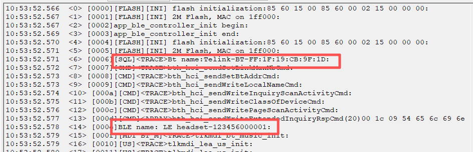
BT Host
This section provides a complete overview of the BT Host interfaces implemented in the Vendor layer, covering key events such as ACL and Profile connection/disconnection. The BT-related implementation is identical across all subsequent application reference designs and is therefore not described again.
- Register ACL connection/encryption/disconnection callbacks to handle pairing information, reconnection, and scanning policies;
static void app_btmgr_aclConnectCB(uint16 handle, uint08 status, uint08 *pBtAddr, uint08 dtype, uint08 hfp_ChId)
This function is the application-layer callback handler for the ACL connection completion event (BTH_EVTID_ACLCONN_COMPLETE). It is mainly used to notify the host of the occurrence of an ACL connection event, as well as to signal the completion of pairing and scanning actions.
static void app_btmgr_aclDisconnCB(uint16 handle, uint08 reason, uint08 *pBtAddr)
This function is the callback handler at the application layer for the ACL disconnection completion event (BTH_EVTID_ACLDISC_COMPLETE). It is primarily used to notify the host computer of the occurrence of an ACL disconnection event, update UI states such as prompt tone and LED indicators, reclaim audio scheduler resources, and trigger reconnection when an ACL link is disconnected due to a timeout (BTH_HCI_ERROR_CONN_TIMEOUT).
static void app_btmgr_aclEncryptCB(uint16 handle, uint08 status, uint08 *pBtAddr, uint08 dtype, uint08 hfp_ChId)
This function is the application-layer callback handler for the link encryption completion event (BTH_EVTID_ENCRYPT_COMPLETE). It is mainly used to initiate SDP service discovery, append the Profile to be connected, and enable the BT sniff feature. In the current SDK design, all Profile connection actions occur after encryption is complete.
static void app_btmgr_ProfConnCB(uint16 handle, uint08 status, uint08 ptype, uint08 usrID, uint08 *pBtAddr, uint08 isFirstProf)
This function is the application-layer callback handler for the profile connection completion event (BTP_EVTID_PROFILE_CONNECT). It is mainly used to update UI states such as prompt tone/LED and to preload the audio scheduler.
static void app_btmgr_ProfDiscCB(uint16 handle, uint08 reason, uint08 ptype, uint08 usrID, uint08 *pBtAddr)
This function serves as the application-layer callback handler for the profile disconnection event (BTP_EVTID_PROFILE_DISCONN). It is mainly used for reclaiming audio scheduler resources and appending profiles to be connected (this action occurs only after the SDP query in the client role has completed).
- According to the device type and the profile information stored in TinySQL, dynamically append profiles such as A2DP, HFP, PBAP, IAP, AVRCP, and ATT to ensure multi-protocol operation.
static void app_btmgr_appendProfile(uint16 aclHandle)
This function is mainly used to append profiles to be connected. Internally, it uses tlkmdi_btacl_appendProf() to append a specific profile to the profile resource manager. After encryption is complete, it actively initiates profile connections to the peer device in sequence based on delayMs.
- Use
tlkmdi_btSet_scan()andtlkmdi_btRecon_start()to control the scanning and reconnection timing.
static void app_btmgr_poweron_action(void)
This function is mainly used to reconnect to the last paired Bluetooth device after the device powers on. If the device’s pairing information is stored in flash memory, call tlkmdi_btRecon_start() to initiate reconnection; otherwise, call tlkmdi_btSet_scan() to enter pairing mode. Detailed information regarding scanning and reconnection is provided in the chapters on scan management and reconnect management; further details are not repeated here.
LE Host
The BLE HID Device registers all BLE HID-related functions.
void app_ble_hid_init(void);
To enable BLE HID functionality, configure the corresponding macro definitions in app_config.h.
#include "stack/ble/host_v1/services/svc_hid/hid_demo/keyboard_cfg.h"
The BLE Unicast Headset registers all LE Audio-related functions. Users only need to provide the Bluetooth device name, advertising interval, and default volume. Refer to the sample code for the implementation details.
struct lea_us_headset_param {
const char *device_name; /** < Advertising/display name. */
uint16_t interval; /** < Extended advertising interval in milliseconds. */
uint8_t volume; /** < Initial render volume (0~255). */
};
void lea_unicast_server_headset_initial(const struct lea_us_headset_param *param);
To enable the LE Audio Path functionality, configure the corresponding macro definitions in app_config.h.
#define TLK_MW_LEA_US_MUSIC_ENABLE 1
#define TLK_MW_LEA_US_VOICE_ENABLE 1
#define CODEC_MIC_FIFO_SAMPLES 2048
#define LE_AUDIO_CODEC_INPUT_TYPE LE_AUDIO_CODEC_TYPE_CODEC
#define LE_AUDIO_CODEC_OUTPUT_TYPE LE_AUDIO_CODEC_TYPE_CODEC
#define APP_AUDIO_ASCSS_SINK_ASE_CNT 1
#define APP_AUDIO_ASCSS_SRC_ASE_CNT 1
Key Functions
| KEY | Single Press | Double Press | Triple Press |
|---|---|---|---|
| KEY1 | Play/Pause Music | Next Track | Enter Pairing Mode |
| KEY2 | Answer the most recent incoming call. 1. If there is no active call, answer the current incoming call. 2. If there is already an active call, answer the latest incoming call and place the previous call on hold. |
Previous Track | N/A |
| KEY3 | Volume + | Volume - | N/A |
| KEY4 | Volume + (BLE_HID) | Volume -(BLE_HID) | Reject the new incoming call. 1. If there is no active call, reject the current incoming call. 2. If there is already an active call, reject the third-party incoming call. |
BT/BLE Audio Source
Functional Overview
The dual-mode Bluetooth Classic + Bluetooth Low Energy Audio (LE Audio) USB Dongle, designed for PCs, laptops, gaming consoles, and other devices to wirelessly transmit audio via Bluetooth to:
-
🎧Traditional Bluetooth headphones (BT Classic / A2DP)
-
🎧Next-generation LE Audio headphones (LE Audio / LC3)
Solves the issue where devices like PCs do not natively support BLE Audio, or where compatibility with both legacy Bluetooth headphones and new LE Audio headphones is required.
Currently, supports the following use cases:
(1) BT Classic connection
(2) BT Classic music
(3) BT Classic calls
(4) LE Audio connection
(5) LE Audio music
(6) LE Audio calls
(7) Coexistence of BT and BLE connections (audio not supported simultaneously)
Functional Flowchart
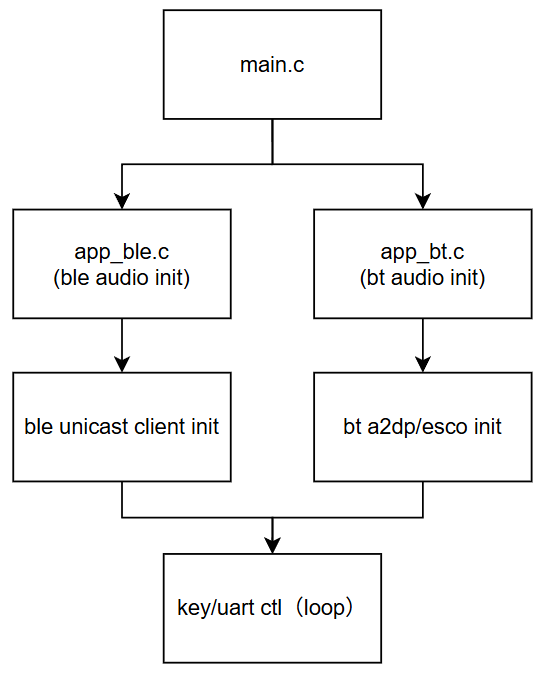
Software Architecture
(1) BLE
BLE Audio processing is implemented in tlkmw\ble\le_audio\lea_unicast_client.c.
- lea_unicast_client_start
Initializes the unicast client profile, gap interfaces, and other related components. Extended scanning is enabled by default for 2 minutes.
- lea_unicast_client_ext_scan_handler
This function serves as the callback for processing broadcast data during the Extended Scan phase of the BLE Audio Unicast Client. It is used to perform the following tasks after a BLE peripheral broadcast packet is detected: parse and validate BLE Audio-related broadcast data, filter discoverable LE Audio devices, report scanned device information to the upper layer, and automatically initiate a connection or re-connect based on existing bond information or SIRK information.
- Parse broadcast data (LTV format)
- Broadcast data uses the LTV (Length-Type-Value) format. The
ltv_unpack()function iterates through all AD Types. For each AD Type parsed, it callslea_unicast_client_check_adv_data_handle(). The parsing results are populated into theadv_datastructure, including: LE Audio flags, Discoverable flags, device name, RSI (Resolvable Set Identifier), and other CAP/CSIS-related information. If parsing fails, the broadcast packet is ignored:
- Broadcast data uses the LTV (Length-Type-Value) format. The
struct cap_device_adv_data_value adv_data = { 0 };
const int ret = ltv_unpack(data, data_len, lea_unicast_client_check_adv_data_handle, &adv_data);
if (ret != LTV_UNPACK_SUCCESS) {
return;
}
- Determine whether the device is a discoverable LE Audio device
- The criteria include the LE Audio broadcast flag and the device being in Limited Discoverable Mode or General Discoverable Mode. In other words, if this is a discoverable LE Audio device, it will be added to the scan table and sent to the host computer for display.
if (adv_data.lea_audio_flags && adv_data.flags & (FLAGS_LE_LIMITED_DISCOVERABLE_MODE | FLAGS_LE_GENERAL_DISCOVERABLE_MODE)) {
if (!cap_device_insert_adv(addr_type, addr, &adv_data)) {
tlkapp_lemgr_sendExtScanDataEvt(addr_type, addr, (uint8_t *) adv_data.complete_name, adv_data.complete_name_len);
}
}
- Checking for Existing Bond Information
- Query the SMP storage to determine if the device has been paired; if pairing_index != 0, it indicates that bonding information exists.
struct ble_host_smp_store_key *p_store_key = ble_host_smp_store_get_pairing_info(addr_type, addr);
uint32_t pairing_index = p_store_key != NULL ? p_store_key->pairing_index : 0;
- Reconnection based on Bond Information or SIRK
if (pairing_index > 0 && tlkapp_lemgr_GetAutoRec())is used to determine whether to re-establish the connection based on bonding information and whether auto-reconnect is enabled.if (audio_device_context.sirk_flag)is used to determine whether to re-connect the second TWS earbud via SIRK.
if (pairing_index > 0 && tlkapp_lemgr_GetAutoRec()) {
// Auto reconnection
} else if (audio_device_context.sirk_flag) {
// Reconnect the second TWS headset through SIRK
}
- lea_unicast_client_sdp_flags_event_handler
- This function is the callback used by the BLE Audio Unicast Client to handle service discovery (SDP/Profile Discovery) events after a connection is established.
- It synchronizes SDP discovery results with the CAP device management module, performs required initialization after SDP completion (such as volume configuration), extracts CSIS SIRK information from discovered devices, and updates the audio device context state.
- lea_unicast_client_cap_device_state_cb
- This function is the CAP device connection/disconnection callback. It is triggered when a BLE audio device is connected or when all BLE audio devices are disconnected. The connection callback is used to add audio tasks, while the disconnection callback is used to remove audio tasks.
- lea_unicast_client_connected_callback
- BLE ACL connection success callback; upon successful connection, processes such as SMP and MTU negotiation are initiated.
- lea_unicast_client_disconnected_callback
- BLE ACL disconnection callback; after disconnection, an extended scan is automatically initiated (2 minutes).
(2) BT
- Refer to the BT Host section in the BT/BLE Headset chapter.
(3) Software Environment
Compile the SDK using Telink IDE. After flashing the current demo firmware, you can operate the device and view logs via the host computer (refer to the Host Computer section for usage instructions). The host computer communicates via a serial port, with a default baud rate of 1500000. The current host computer supports functions such as BT/BLE scanning, connecting, disconnecting, and clearing the pairing table.
(4) Operation Steps
USB Connection:
The development board requires a USB connection. Use the UAC to connect the computer’s audio to the development board’s audio. On the computer, select the audio device emulated by the UAC.
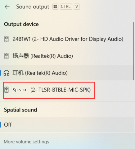
UART Connection:
Connect the UART and operate using the host computer. For usage instructions, refer to the Host Computer section.
- Scanning BT/BLE Devices
Click start search, open ble scan to search for available audio devices.
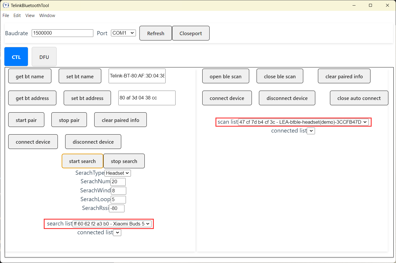
- Connecting BT/BLE Devices
Discovered devices are displayed in the search list and scan list. Select the target device and click Connect BT Device or Connect BLE Device to establish a connection. After a successful connection, the device appears in the connected device list.
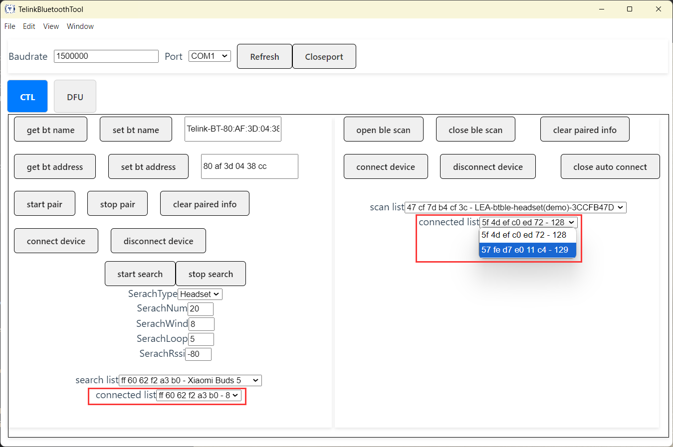
- Disconnecting BT/BLE Devices
Select the device to be disconnected from the connected device list and click Disconnect.
- Getting, Setting the BT Name or BT Address
Click get BT Name or get BT Address to obtain the current device name or MAC address.
To modify the BT name or BT address, update the corresponding value and click Set BT Name or Set BT Address.
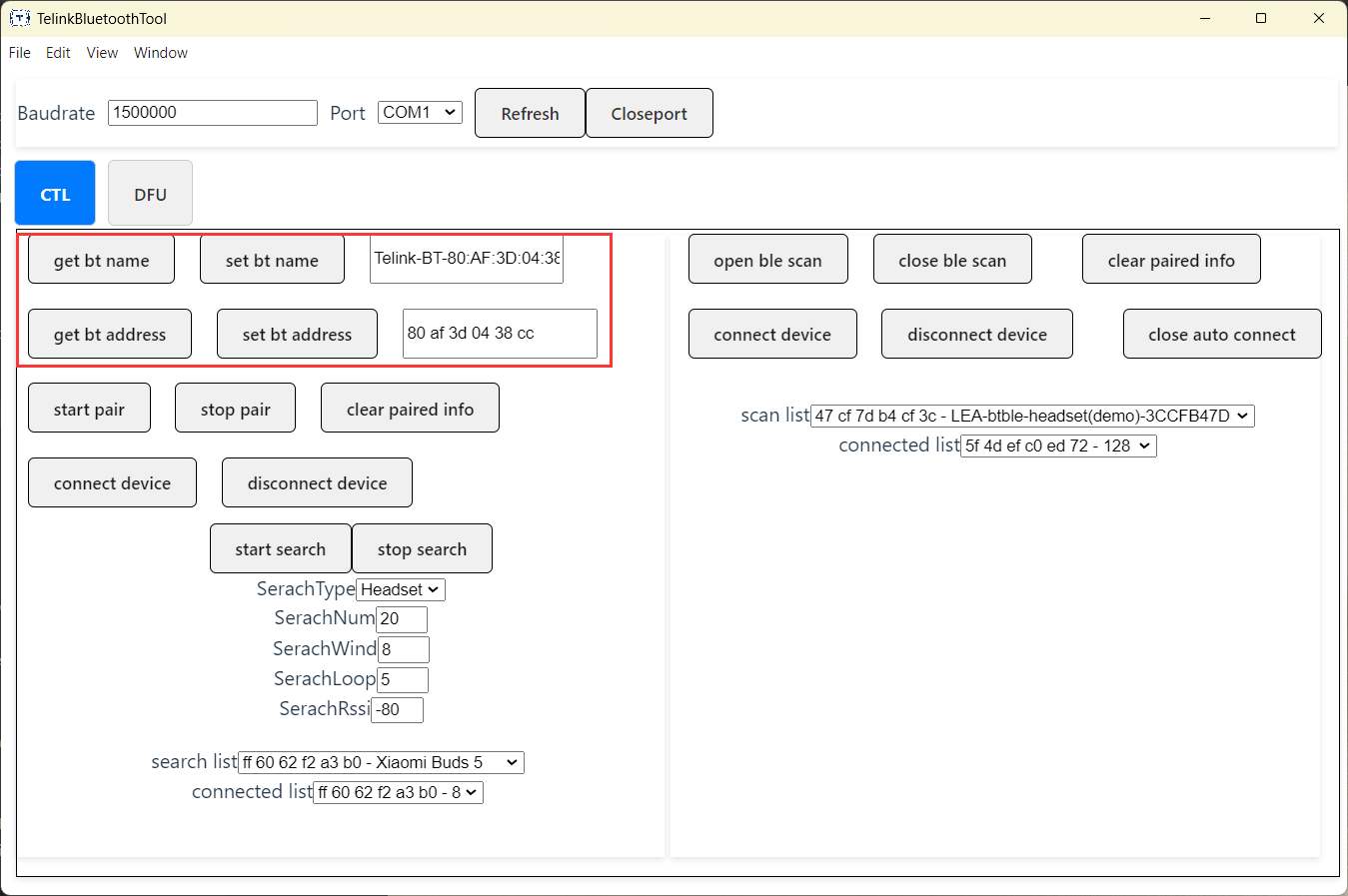
- Clearing Pairing Information
Clears the pairing and bonding information between the device and the headset. After the information is cleared, the devices must be paired again before reconnecting.
- Enabling/Disabling BT Pairing
Enables or disables BT pairing mode.
- Enabling/Disabling BLE Auto Reconnection
When pairing information is available, the device can automatically reconnect based on the stored bonding information. If auto reconnection is disabled, automatic reconnection will not be performed.
Music and Call Experience:
After a BT or BLE audio device is successfully connected, music playback, voice calls, call recording, and other audio functions can be performed. Audio from the PC is transmitted through the UAC interface and then forwarded to the headset over Bluetooth.
(5) UI Instructions
| Button | Short press | Double press | Triple press |
|---|---|---|---|
| key1(SW2/SW24) | Play/Pause Music | Next Track | Start Pairing |
| key2(SW4/SW23) | N/A | Previous Track | BT/BLE audio Switch |
| key3(SW3/SW20) | Volume+(BT) | N/A | N/A |
| key4(SW5/SW21) | Volume-(BT) | N/A | N/A |
| SOURCE LED | Flashing | Breathing | Steady On |
|---|---|---|---|
| LED1(White) | Disconnected | Connected | N/A |
| LED2(Red) | Disconnected | Connected | N/A |
A2DP In BIS Out
Overview
This section provides a brief introduction to the A2DP_TO_BIS reference design in the Bluetooth Audio SDK to help users understand and perform secondary development. The primary function of this application is to play A2DP music packets received via Bluetooth locally and convert them into Auracast broadcast packets for transmission. Multiple receivers can simultaneously receive these broadcast packets and play them in sync with the source.
According to their functions, this application can be divided into the following three roles:
(1) Source: Decodes received A2DP audio packets into PCM data for local playback, and simultaneously encodes the PCM data into Auracast broadcast packets for transmission;
(2) Sync: After pairing is complete, automatically scans for the Broadcast Source currently broadcasting the demo and plays in sync with the Source; If the Source is lost, the Sync node is not automatically resume synchronization.
(3) Sink: After switching is complete, the device begins broadcasting a BIS-Sink link. Users can pair and connect using devices that support Auracast Assistant, synchronize the desired Source using the BASS protocol, and complete the synchronization. For details, please refer to the Broadcast Sink Demo in the BLE example.
Key features are as follows:
-
BT-related features:
- Supports BT link pairing, reconnection, role switching, and other functions
- Supports Secure Session Profile (SSP) and Adaptive Frequency Hopping (AFH)
- Supports SNIFF mode
- Bluetooth audio supports SBC decoding
- Supports BT A2DP-SINK, AVRCP, SPP, and GATT protocols
-
BIS-related features:
- Supports LC3 encoding
- Supports BASS protocol
- Supports PBP protocol
-
Common features:
- Supports WFI mode
- Supports ASRC sampling rate conversion and PPM multi-device clock offset adjustment
Application Interfaces
BT
- Refer to the BT Host section in the btble_headset chapter
BIS
- Refer to the Broadcast Demo section in the ble_example chapter
UI Instructions
| Button | Single Press | Double Press | Triple Press |
|---|---|---|---|
| key1(SW2/SW24) | Play/Pause Music | Next Track | Start Pairing |
| key2(SW4/SW23) | Switch BIS Role | N/A | N/A |
| key3(SW3/SW20) | Volume+(BT) | Volume-(BT) | N/A |
| SOURCE LED | Flashing | Breathing | Steady On |
|---|---|---|---|
| LED1(White) | Disconnected | Connected | N/A |
| LED2(Red) | Disconnected | Connected | N/A |
BT/TPSLL TWS
Overview
This section describes the implementation of the BT/TPSLL TWS reference design in the Bluetooth Audio SDK, as well as the accompanying TPSLL Audio Dongle reference design. It also provides detailed explanations of the modules that are most relevant to secondary development, helping users better understand the reference design and shorten the development cycle from project initiation to mass production.
Typical application scenarios of the BT/TPSLL TWS reference design include:
(1) Bluetooth Classic TWS(True Wireless Stereo) Mode: Establishes a connection with a smartphone or PC via Classic Bluetooth to enable music playback or phone calls—the core functionality of traditional TWS earbuds.
(2) 2.4 GHz Low-Latency Audio Mode (Used with a 2.4 GHz Dongle): Establishes a connection via a 2.4 GHz link (Telink Proprietary Synchronous Link Layer, TPSLL) and a 2.4 GHz dongle (the dongle end uses the TPSLL Audio Dongle Reference Design). The 2.4 GHz dongle can be plugged into a PC, smartphone, or tablet to enable low-latency audio applications. This is commonly used in gaming scenarios with strict latency requirements and offers excellent cross-device compatibility. Additionally, compared to Classic Bluetooth, it delivers significant improvements in connection stability, interference resistance, range, power consumption, and audio codecs.
(3) Audio Mixing Mode with Simultaneous Bluetooth Classic TWS and 2.4 GHz Low-Latency Audio: While Classic Bluetooth TWS is active, 2.4 GHz audio can be connected at any time; conversely, while 2.4 GHz low-latency audio is active, Classic Bluetooth TWS can be connected at any time. This ultimately creates an effect of multi-device audio input and mixing; This design effectively resolves connectivity conflicts in wireless scenarios while allowing users to monitor audio inputs from multiple devices, delivering an exceptional user experience without compromising audio quality or introducing latency.
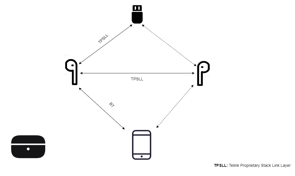
Key features are as follows:
-
BT-related features:
- Supports BT link pairing, reconnection, role switching, and other functions
- Supports Secure Session Profile (SSP) and Adaptive Frequency Hopping (AFH)
- Supports SNIFF mode
- Supports WFI and Suspend mode
- BT music supports AAC/SBC codec formats
- BT calls support CVSD and MSBC codec formats
- Supports BT HFP-HF, A2DP-SINK, AVRCP, SPP, and GATT protocols
- Supports wireless updates via BT SPP/GATT
- Supports audio EQ, music mode supports 9-band EQ, call mode uplink supports 4-band EQ, and call mode downlink supports 4-band EQ
- Supports Bluetooth call packet loss compensation (PLC)
- Supports automatic gain control (AGC) for the microphone
- Supports dynamic range control (DRC)
- Supports Automatic Echo Cancellation (AEC)
- Supports Noise Suppression (NS)
- Supports BF Beamforming
- Supports NN noise reduction for BT call uplink
-
TPSLL-related features:
- Supports TPSLL link pairing and reconnection
- TPSLL Dongle music supports mono/stereo modes and supports LC3 PLUS 48K 24-bit
- TPSLL Dongle phone supports mono/stereo modes and supports downlink LC3 PLUS 48K 24-bit and uplink 16K 24-bit
- Supports low-latency mode (approx. 28 ms) and ultra-low-latency mode (approx. 18 ms)
- Supports adaptive frequency hopping
- Supports sniff mode
- Supports WFI and suspend modes
-
BT and TPSLL Coexistence Features:
- Any BT scenario can coexist with any TPSLL scenario
- When coexisting with a phone call, only one MIC uplink is enabled by default; the specific channel is selectable
-
TWS-related features:
- Supports mono and stereo modes
- Supports TWS stereo pairing
- Supports master-slave switching between earbuds
- Supports mixed playback and separate playback of notification tones (ADPCM format)
- Supports Hybrid ANC mode
UI Instructions:
(1) Button Functions
- Headset Side
| Button | Short Press | Double Press | Triple Press | Hold | Long Press (1~2s) |
|---|---|---|---|---|---|
| key1(SW24) | Play/Pause Music | Volume- | Save | N/A | N/A |
| key2(SW23) | Answer Call | Previous Track | Volume+ | N/A | N/A |
| key3(SW20) | 3s Pairing | Master/Slave Switch | Next Track | N/A | siri |
| key4(SW21) | 10s Pairing/Power On | N/A | End Call | N/A | Power Off (Saves Settings) |
- Dongle Side
| Button | Short Press | Double Press | Triple Press | Hold | Long Press (1~2s) |
|---|---|---|---|---|---|
| key1(SW4) | N/A | Pairing | N/A | N/A | N/A |
(2) LED Indicator Descriptions
- Earbud Side
| TWS LED | Fast Flash | Slow Flash | Breathing | Steady On |
|---|---|---|---|---|
| LED1(White) | Pairing State | Reconnection State | Connected State | N/A |
| LED2(Red) | Pairing State | Reconnection State | Connected State | N/A |
(3) Dongle Side
| Dongle LED | Fast Flash | Slow Flash | Breathing | Steady On |
|---|---|---|---|---|
| LED1(Blue) | Pairing State | Reconnection State | N/A | Connected State |
| LED2(Red) | Pairing State | Reconnection State | N/A | Connected State |
Operating Instructions:
(1) Compilation and Programming Instructions
For the compilation and programming process of the BT/TPSLL TWS Reference Design and the TPSLL Audio Dongle Reference Design, please refer to the Get Started section. The following lists only the points to note.
- BT/TPSLL TWS Reference Design
- The TL751x used in the BT/TPSLL TWS is a dual-core design. After importing the TL751x project, compile the controller project first, then compile the bttpsll_tws project. When compiling the controller, set CONTROLLER_MODE to BT/TPSLL_TWS in the
vendor\controller\controller_config.hfile.
- The TL751x used in the BT/TPSLL TWS is a dual-core design. After importing the TL751x project, compile the controller project first, then compile the bttpsll_tws project. When compiling the controller, set CONTROLLER_MODE to BT/TPSLL_TWS in the
#define CONTROLLER_MODE BTTPSLL_TWS
After the bttpsll_tws project is compiled, two bin files will be generated and stored in the
tl_bluetooth_audio_sdk\telink_b91m_bluetooth_src\tlk_bluetooth_src\build\TL751X\bttpsll_tws directory, with filenames bttpsll_tws&n22_controller_120.bin / bttpsll_tws&n22_controller_121.bin. The two bin files must be flashed separately to the zero address of the left and right TWS earbuds using the BDT tool. Additionally, the beep firmware must be flashed to address 0x001A0000, and the DSP firmware to address 0x00200000.
-
TPSLL Audio Dongle Reference Design:
- The TL721x used in the TPSLL Audio Dongle is a single-core design. After importing the TL721x project, simply compile tpsll_audio_dongle. After successful compilation, tpsll_audio_dongle.bin is generated in:
tl_bluetooth_audio_sdk\telink_b91m_bluetooth_src\tlk_bluetooth_src\build\TL721X\tpsll_audio_dongle
- The TL721x used in the TPSLL Audio Dongle is a single-core design. After importing the TL721x project, simply compile tpsll_audio_dongle. After successful compilation, tpsll_audio_dongle.bin is generated in:
It can be flashed to the TL721x development board using BDT.
(2) Configuration Instructions
For the BT/TPSLL TWS to function properly, the following configurations must be performed after flashing the necessary firmware.
- BT/TPSLL TWS Configuration
- USB ID Configuration
- On the earbud side, the TWS USB ID must be stored at flash address ‘0x7f8000’; the left and right earbuds must be programmed with 0x20 and 0x21, respectively.
- BT Configuration
- The BT name and MAC address can be configured via the host computer.
- USB ID Configuration
Configurations related to BT mode are integrated into the host computer tool (TelinkBluetoothTool). The following are instructions for using the host computer tool:
The PC communicates with the development board via the serial port. Before use, connect the TL751x development board to the computer using a serial port adapter (connect the earbuds’ PC6 and PB7 pins to the adapter’s RX and TX pins, respectively), and set the baud rate to 1,500,000. In the host computer tool, select the serial port and click “Open Serial Port” to establish communication between the host computer and the development board. To set the BT name and address, click “Get BT Name” and “Set BT Name”.
-
TPSLL Audio Dongle Configuration
- On the dongle side, a custom 6-byte MAC address must be written to flash address ‘0x1ff100’. Note that the value must not be all‑zeros or all‑fs.
Once the above configuration is complete, you can successfully pair both earbuds and establish BT and TPSLL connections.
(3) TWS Pairing Instructions
TWS pairing can be initiated through the buttons. After both earbuds are powered on, press KEY4 once on each earbud to start pairing. When the following logs appear on the master and slave earbuds respectively, TWS pairing has completed successfully:
- TPT_HEADSET_STATE_CONNECTED:TPT_HEADSET_ROLE_MASTER
- TPT_HEADSET_STATE_CONNECTED:TPT_HEADSET_ROLE_SLAVE
(4) BT Connection Instructions
Press KEY4 once on both earbuds. After TWS pairing is completed, scanning is enabled automatically. Enable Bluetooth on the mobile phone and connect to the device according to the configured BT name.
After the connection is established, the LED status of both earbuds changes from fast blinking to synchronized breathing. Music playback and voice calls can then be performed through the connected earbuds. For audio output verification, connect the earphones to the left-channel audio output on both earbuds.
(5) TPSLL Connection Instructions
Connect the dongle to a PC through USB. A device named "TLSR-BTBLE-MIC-SPK" appears in the operating system audio device list.
Press KEY4 once on both earbuds. After TWS pairing is completed, the earbuds enter pairing mode. Double-press KEY1 on the dongle to establish a TPSLL connection with the TWS earbuds.
Once connected, the TWS earbuds’ LEDs will change from rapid flashing to synchronized breathing, and the dongle LED will change from rapid flashing to steady on. At this point, play music or make a call from your computer, select TLSR-BTBLE-MIC-SPK as the audio output device, and a complete audio connection will be established.
System Architecture
(1) Earbud Software Architecture
The software architecture of the earbuds is shown in the figure below. It mainly consists of the Application, RTOS, protocol stack (Profiles, GAP, SDP, SMP, L2CAP, etc.), Audio Path, HCI (the interface layer between the Host and Controller), controllers (BT Controller and TPSLL Controller), RF/PHY, and Power Manager, etc.
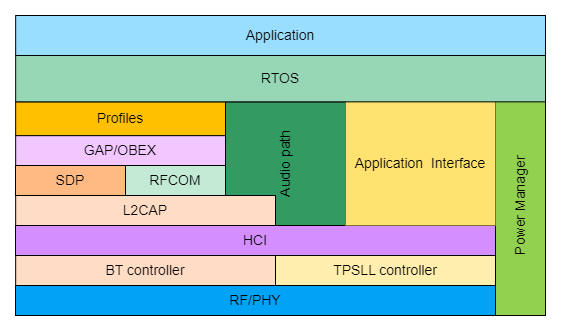
Based on the BT/TPSLL TWS reference design, this document focuses on the components most relevant to secondary development. Some implementation principles are briefly introduced, while the Bluetooth standard protocols and the implementation details of the core libraries are not covered. The main topics include:
- TWS pairing, bonding, reconnection, and switching between single-earbud and dual-earbud modes
- Seamless switching between TWS earbuds
- Audio path implementation on the earbud side
(2) Dongle Software Architecture
The software architecture of the dongle is shown in the figure below. It mainly consists of the Application, Application Interface, Audio Path, HCI (the interface layer between the Host and Controller), TPSLL Controller, RF/PHY, and Power Manager, etc.
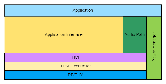
Based on the TPSLL Audio Dongle reference design, this document focuses on the components most relevant to secondary development. Some implementation principles are briefly introduced, while the implementation details of the core libraries are not covered. The main topics include:
- Pairing and reconnection between the dongle and TWS earbuds
- Audio path implementation on the dongle side
Software Modules
(1) Earbud Software Modules
TWS Pairing, Bonding, Reconnection, and Single-/Dual-Earbud Mode Switching:
1) Pairing Modes
Before introducing the 10-second pairing and 3-second pairing procedures, it is necessary to understand the concept of a pairing mode. In the predefined application scenarios, the reference design supports two pairing modes:
-
Wired Pairing: This mode is typically used for TWS earbuds with a charging case.
- Because communication is available between the earbuds and the charging case, the charging case can actively synchronize pairing information between the left and right earbuds. In this reference design, the charging case exchanges the MAC addresses of the left and right earbuds and generates unified pairing information according to predefined rules. The two earbuds then perform pairing using the same private pairing information, providing improved security. Unless otherwise specified, the 10-second pairing and 3-second pairing procedures described in this document assume the wired pairing mode.
-
Wireless Pairing: This mode is typically used for TWS speakers.
- Since no charging case is available, there is no mechanism to synchronize pairing information between devices. In this case, the left and right devices perform pairing using a public address and channel. After pairing is completed, the devices exchange MAC addresses. Subsequent pairing operations can then be performed using a more secure mechanism. Compared with wired pairing, wireless pairing is more susceptible to interference during the initial pairing process because it relies on a public address and channel.
2) Determination of the Primary and Secondary Earbud Roles
The device whose pairing packet is first received by the peer becomes the primary earbud. For example, if device A sends a pairing packet and device B receives it first, device A becomes the primary earbud and device B becomes the secondary earbud.
- Primary Earbud: it has full control of the system, including: a complete BT connection, a complete dongle connection, decision-making authority for various connection requests, the ability to respond to various connection requests and information synchronization requests, and control over the uplink microphone, among other functions.
- Secondary Earbud: it has monitoring capability but no control authority. Its responsibilities include: virtual dongle connections, virtual BT connections, initiating various connection requests, initiating various information synchronization requests, and more.
3) Switching Between Single-Earbud and Dual-Earbud Modes
In practical applications, users may operate only one earbud or speaker. This operating state is referred to as single-earbud mode. When both earbuds or speakers are operating simultaneously, the system is in dual-earbud mode.
- Single-Earbud Mode: If pairing is not completed before the pairing timeout expires, the system assumes that only one earbud has been removed from the charging case or only one speaker has been powered on. The device then enters single-earbud mode. In this mode, the device can establish a BT connection with a mobile phone, a TPSLL connection with a dongle, and support all normal audio playback scenarios. In addition, pairing with another earbud must remain available at any time so that the system can transition from single-earbud mode to dual-earbud mode. When this transition occurs, the device that was already operating in single-earbud mode always becomes the primary earbud, while the newly joined device becomes the secondary earbud.
- Dual-Earbud Mode: If pairing is completed successfully, the system enters dual-earbud mode. In this mode, the device can establish a BT connection with a mobile phone, a TPSLL connection with a dongle, and support all normal audio playback scenarios. Dual-earbud mode also supports seamless switching, which is sometimes referred to as primary/secondary role switching. In typical usage scenarios, one earbud may be returned to the charging case, or one speaker may be powered off. This causes the system to transition from dual-earbud mode to single-earbud mode. If the device being removed or powered off is currently the primary earbud, a primary/secondary role switch is performed first to ensure that the remaining active device becomes the primary earbud. This behavior is consistent with the design principle that a device operating in single-earbud mode must always act as the primary device.
4) 10-Second TWS Pairing and BT Pairing
The 10-second TWS pairing procedure is illustrated in the figure below.
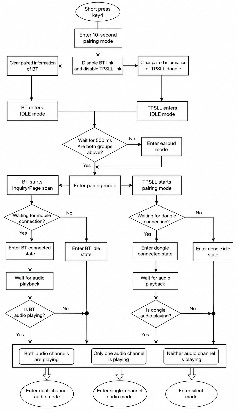
In the BT/TPSLL TWS reference design, the TPSLL link plays a critical role. It is used for TWS pairing, information synchronization, virtual BT link management, and other inter-earbud communication functions. In addition, the audio link between the TWS earbuds and the dongle is also established through the TPSLL link. Since the BT functionality is based on standard Bluetooth protocols and the corresponding interfaces are documented separately, it is not discussed in detail here. Therefore, this document focuses primarily on the upper-layer application interfaces of the TPSLL link, as well as the BT interfaces that are relevant to user development;
The implementation principles and function interfaces involved in each stage of the process are described below:
- Initialization: The entire Bluetooth Audio SDK adopts a modular architecture. Before invoking any lower-layer component, the application layer must initialize the corresponding module by calling its initialization interface;
static void tlkapp_host_init(void)
{
tlkmw_host_init();
tlksys_task_regEvtCB(TLKSYS_TASKID_HOST,TLKSYS_TASK_EVT_HOST_HCI,tlkapp_host_hci_handler);
#if (TLK_STK_BT_ENABLE)
tlkapp_host_addModule(tlkapp_host_bt_getModule());
#endif
#if (TLK_STK_BLE_ENABLE)
tlkapp_host_addModule(tlkapp_host_le_getModule());
#endif
#if (TLK_STK_BT_TPSLL_ENABLE)
tlkapp_host_addModule(tlkapp_host_tph_getModule());
#endif
#if (TLKSTK_BTTPSLL_TWS_ENABLE)
tlkapp_host_addModule(tlkapp_host_tpt_getModule());
#endif
#if (TLK_STK_TPD_ENABLE)
tlkapp_host_addModule(tlkapp_host_tpd_getModule());
#endif
#if (TLK_STK_TPMD_ENABLE)
tlkapp_host_addModule(tlkapp_host_tpmd_getModule());
#endif
}
As shown in the code above, only the TLKSTK_BTTPSLL_TWS_ENABLE macro is enabled in the BTTPSLL TWS reference design. This macro enables the registration of the TWS functional module.
TlkAppHostModule_t* tlkapp_host_tpt_getModule(void)
{
static const TlkAppHostModuleCfg_t cfgs = {
.hostType = TLKSYS_MSG_HOST_TYPE_TPT,
.init = tlkapp_host_tpt_init,
.start = tlkapp_host_tpt_start,
.input = tlkapp_host_tpt_msgHandle,
};
static TlkAppHostModule_t module = {
.cfgs = &cfgs,
};
return &module;
}
As shown above, the registration of the TWS functional module mainly consists of three functions:
static void tlkapp_host_tpt_init(void)
Function: Used to initialize the upper-layer TWS application interfaces, including power management initialization, state machine initialization, multi-core communication initialization, TWS role initialization, and pairing parameter initialization.
static void tlkapp_host_tpt_start(void)
Function: Used to initialize the pairing state machine, configure pairing parameters, and start timer tasks.
int tlkapp_host_tpt_msgHandle(uint16 msgID, uint08 *pData, uint16 dataLen)
Function: Acts as a message handler. It processes different events according to the received message type. Most of these events are triggered by key operations. Different key combinations generate different messages and trigger different event-handling procedures.
int tlkapp_host_tpt_msgHandle(uint16 msgID, uint08 *pData, uint16 dataLen)
{
(void) pData;
(void) dataLen;
switch(msgID){
case TLKSYS_TPT_MSGID_3S_PAIR:
tlkmdi_bt_tpt_pair_start_req(TPT_HOST_HEADSET_SETUP_MODE_3S,pData);
break;
case TLKSYS_TPT_MSGID_10S_PAIR:
tlkmdi_bt_tpt_pair_start_req(TPT_HOST_HEADSET_SETUP_MODE_10S,pData);
break;
case TLKSYS_TPT_MSGID_ENTER_LOW_LATENCY_MODE:
tlkmdi_bt_tpt_pair_start_req(TPT_HOST_HEADSET_SETUP_MODE_ULTRA_LOW_LATENCY,pData);
break;
case TLKSYS_TPT_MSGID_START_HANDOVER:
tlkmdi_bt_tpt_handover_start();
break;
case TLKSYS_TPT_MSGID_SEND_KEY:
tlkapp_host_tpt_recvSendKeyDeal(pData,dataLen);
break;
case TLKSYS_TPT_MSGID_SHUT_DOWN:
tlksys_pm_setChn(TLKSYS_PM_CHN_SYS,0,0);
tlkmdi_bt_tpt_shut_down();
break;
default:
return -TLK_ENOSUPPORT;
}
return TLK_ENONE;
}
- Entering 10-Second Pairing Mode: Press KEY4 once to enter the 10-second pairing mode. The 10-second pairing event is obtained through the key-scanning module (this module is described in detail in the common SDK components). The corresponding callback function is then invoked when the event is detected.
void tlkmdi_bt_tpt_pair_start_req(uint8_t isRefactory, uint08 *peerMac)
Parameter 1: isRefactory, indicates the link establishment mode. For 10-second pairing, this parameter is set to TPT_HOST_HEADSET_SETUP_MODE_10S. The reference design supports several link establishment modes, including this mode.
typedef enum
{
TPT_HOST_HEADSET_SETUP_MODE_IDLE,
TPT_HOST_HEADSET_SETUP_MODE_NORMAL,
TPT_HOST_HEADSET_SETUP_MODE_3S,
TPT_HOST_HEADSET_SETUP_MODE_10S,
TPT_HOST_DONGLE_SETUP_MODE_NORMAL,
TPT_HOST_DONGLE_SETUP_MODE_PAIRING,
TPT_HOST_DONGLE_SETUP_MODE_CC_HEADSET,
TPT_HOST_HEADSET_SETUP_MODE_ULTRA_LOW_LATENCY,
TPT_HOST_HEADSET_SETUP_MODE_EXIT_ULTRA_LOW_LATENCY,
} tpt_headset_setup_mode_for_host_e;
Parameter 2: peerMac, specifies the peer device MAC address used for wired pairing through the charging case. The default value is NULL, indicating that the two earbuds perform pairing wirelessly.
- Closing Existing Links and Deleting Pairing Information: In the callback function of the 10-second pairing event, the system first checks whether any BT links are active. These links include pairing, reconnection, and active connections. If any BT link exists, the system attempts to disconnect it before deleting the pairing information. The pairing information is deleted in the following subfunction:
void tlkmdi_bt_tpt_pair_start(uint8_t isRefactory, uint08 *peerMac)
- Entering TPSLL Pairing Mode: After all BT links have been disconnected, the state machine transitions to the next state and attempts to terminate the TPSLL link. The system then waits for the TPSLL disconnection event to be reported. The following interfaces are involved in this process:
bool tlkmdi_bt_tpt_pair_procs(void)
Except for events that require interaction with the lower layers, most link-establishment state transitions are handled within the functions listed above;
- Waiting 500 ms to Determine Whether TWS Pairing Is Successful: In the following disconnection event callback function, the state machine transitions to a new state and initializes the pairing parameters. One of these parameters is a timeout value of 500 ms, which is used while waiting for TWS pairing.
static int tlkmdi_bt_tpt_headset_disconnect_CB(uint8_t *pData, uint16_t dataLen)
The actual TWS pairing procedure is started in the tlkmdi_bt_tpt_pair_procs function according to the current state-machine state; The following key interfaces are involved in starting the pairing procedure:
tpsll_hci_sendWriteHeadsetAccessCodeAndChnIDCmd(sTlkMdiBtTpsllTwsCtrl.ble_ac, sTlkMdiBtTpsllTwsCtrl.ble_ch);
tpsll_hci_sendHeadsetConnectSetupCmd(TPT_HOST_HEADSET_SETUP_MODE_10S, TLK_MDI_BT_TPT_SETUP_CONTROLLER_TIMEOUT_US);
If pairing succeeds, a pairing-success event is reported. In the corresponding callback function, the pairing information is stored and the state machine transitions to the next state. The following interfaces are involved:
static int tlkmdi_bt_tpt_headset_connected_CB(uint8_t *pData, uint16_t dataLen)
- Entering Pairing Mode: The state machine in tlkmdi_bt_tpt_pair_procs then transitions to the pairing state, where both BT pairing and dongle pairing are initiated. It should be noted that only the master earbud or an earbud operating in single-ear mode can initiate pairing. A secondary earbud is not allowed to initiate pairing. Therefore, a role check is performed, and any existing BT link is terminated before pairing begins. The following function is involved:
static void tlkmdi_bt_tpt_pair_enter(bool isSingle)
- Waiting for Connection: In tlkmdi_bt_tpt_pair_procs, the system continuously checks whether either a BT connection or a dongle connection has been established. Once either connection is successfully established, the link-establishment state machine is reset. Regardless of whether the device connects to a mobile phone or a dongle, a connection-complete event is reported when the connection succeeds. The application layer updates the state machine accordingly based on this event; For a secondary earbud, once it detects that the master earbud has established a BT connection, a virtual BT link is automatically created. Similarly, when the master earbud establishes a dongle connection, a virtual dongle link is automatically created; These operations are handled entirely by the lower-layer implementation. The application layer only receives a link-connection-complete event after the virtual link has been successfully established.
At this point, the 10-second pairing procedure is complete. The system then enters the connected state, where it can perform various operations such as music playback, voice calls, and audio mixing in different usage scenarios.
5) 3-Second Pairing for TWS Earbuds
The 3-second pairing process for TWS earbuds is shown in the figure below. Note that the sections marked in red represent the key differences from the 10-second pairing process.
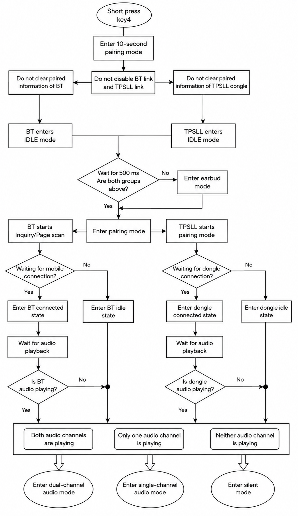
Following the steps above, the implementation principles and function interfaces used for each section are described below:
- Entering 3-second pairing mode: Pressing key3 enters 3-second pairing mode. Similar to 10-second pairing, 3-second pairing is triggered by a button press that scans for devices, and a callback function is invoked within the event.
void tlkmdi_bt_tpt_pair_start_req(uint8_t isRefactory, uint08 *peerMac)
Parameter 1 Indicates the link establishment mode. For 3-second pairing, the value of isRefactory is set to: TPT_HOST_HEADSET_SETUP_MODE_3S.
-
Closing Existing Links: In the callback function for the 10-second pairing event, the system first attempts to disconnect existing BT links and then deletes the stored pairing information. In contrast, the 3-second pairing procedure does not delete the existing pairing information. This is the most significant difference between the two pairing modes. The purpose of this design is to allow users to connect to a new dongle or a new mobile phone conveniently. Once a new device is successfully connected, its pairing information automatically replaces the existing pairing information. If no new device is connected, the device will continue to use the previously stored pairing information for reconnection after a pairing timeout or after being powered on again.
-
Entering TPSLL Pairing Mode: After all BT links have been disconnected, the state machine transitions to the next state and attempts to terminate the TPSLL link. The system then waits for the TPSLL disconnection event to be reported. The following interfaces are involved in this process:
bool tlkmdi_bt_tpt_pair_procs(void)
Except for events that require interaction with the lower layers, most link-establishment state transitions are handled within the functions listed above.
- Waiting 500 ms to Determine Whether TWS Pairing Is Successful: In the following disconnection event callback function, the state machine transitions to a new state and initializes the pairing parameters. One of these parameters is a timeout value of 500 ms, which is used while waiting for TWS pairing.
static int tlkmdi_bt_tpt_headset_disconnect_CB(uint8_t *pData, uint16_t dataLen)
The actual TWS pairing procedure is started in the tlkmdi_bt_tpt_pair_procs function according to the current state-machine state; The following key interfaces are involved in starting the pairing procedure:
tpsll_hci_sendWriteHeadsetAccessCodeAndChnIDCmd(sTlkMdiBtTpsllTwsCtrl.ble_ac, sTlkMdiBtTpsllTwsCtrl.ble_ch);
tpsll_hci_sendHeadsetConnectSetupCmd(TPT_HOST_HEADSET_SETUP_MODE_10S, TLK_MDI_BT_TPT_SETUP_CONTROLLER_TIMEOUT_US);
If pairing succeeds, a pairing-success event is reported. In the corresponding callback function, the pairing information is stored and the state machine transitions to the next state. The following interfaces are involved:
static int tlkmdi_bt_tpt_headset_connected_CB(uint8_t *pData, uint16_t dataLen)
- Entering Pairing Mode: The state machine in tlkmdi_bt_tpt_pair_procs then transitions to the pairing state, where both BT pairing and dongle pairing are initiated. It should be noted that only the master earbud or an earbud operating in single-ear mode can initiate pairing. A secondary earbud is not allowed to initiate pairing. Therefore, a role check is performed, and any existing BT link is terminated before pairing begins. The following function is involved:
static void tlkmdi_bt_tpt_pair_enter(bool isSingle)
- Waiting for Connection: In tlkmdi_bt_tpt_pair_procs, the system continuously checks whether either a BT connection or a dongle connection has been established. Once either connection is successfully established, the link-establishment state machine is reset. Regardless of whether the device connects to a mobile phone or a dongle, a connection-complete event is reported when the connection succeeds. The application layer updates the state machine accordingly based on this event. For a secondary earbud, once it detects that the master earbud has established a BT connection, a virtual BT link is automatically created. Similarly, when the master earbud establishes a dongle connection, a virtual dongle link is automatically created. These operations are handled entirely by the lower-layer implementation. The application layer only receives a link-connection-complete event after the virtual link has been successfully established.
At this point, the 3-second pairing procedure is complete. The system then enters the connected state, where it can perform various operations such as music playback, voice calls, and audio mixing in different usage scenarios.
6) TWS Earbud Reconnection
From a practical application perspective, TWS earbud reconnection scenarios can be categorized into the following two types:
-
Power-On Reconnection: This is a normal behavior. It typically occurs when the earbuds have previously been connected to a mobile phone or a dongle. After the earbuds are powered off and then powered on again, the reconnection procedure is automatically initiated.
-
Abnormal Disconnection Reconnection: This is triggered by unexpected disconnection events, such as connection timeouts caused by excessive distance between devices or other abnormal disconnection conditions.
The overall power-on reconnection procedure is illustrated below:
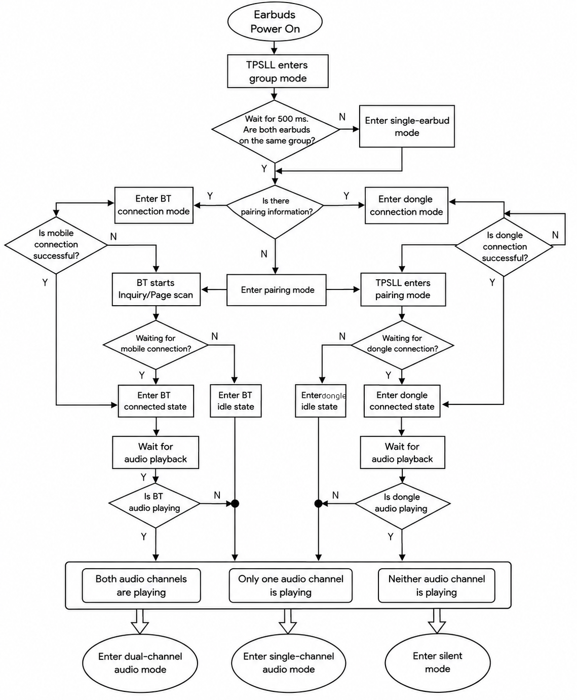
In practical applications, abnormal-disconnection reconnection scenarios can be divided into the following categories according to the device relationship involved:
- Abnormal Disconnection Between the Primary and Secondary Earbuds: If the connection between the primary and secondary earbuds is lost due to an unexpected event or because the devices move out of range, the primary earbud switches to single-ear mode and continues to maintain its pairing, reconnection, or connection state. Once disconnected from the primary earbud, the secondary earbud terminates all existing links and waits until TWS pairing with the primary earbud is re-established. After successful pairing, all required links are recreated virtually. It should be noted that only the primary earbud can initiate pairing and reconnection procedures. The secondary earbud only maintains virtual links when operating in the connected state.
- Abnormal Disconnection Between the Earbuds and the Dongle: If the connection between the earbuds and the dongle is lost because of an unexpected event or excessive distance, both the master earbud and the dongle initiate reconnection procedures. Once the master earbud reconnects to the dongle, the secondary earbud automatically creates a virtual dongle link and resumes monitoring audio packets transmitted from the dongle.
- Abnormal Disconnection Between the Earbuds and the Mobile Phone: If the connection between the earbuds and the mobile phone is lost because of an unexpected event or excessive distance, both the master earbud and the mobile phone initiate reconnection procedures. Once the master earbud reconnects to the mobile phone, the secondary earbud automatically creates a virtual BT link and resumes monitoring data packets transmitted from the mobile phone.
- Additional Notes on Abnormal Disconnection Handling: To ensure link reliability, the system does not allow the secondary earbud to disconnect from the dongle before the master earbud. The secondary earbud always waits for a notification from the master earbud before disconnecting from the dongle. Similarly, the secondary earbud is not allowed to disconnect from the mobile phone before the master earbud. It always waits for a notification from the master earbud before disconnecting from the mobile phone. This design significantly reduces link-management complexity and improves overall connection stability. In addition, neither the dongle nor the mobile phone is aware of the existence of the secondary earbud. The secondary earbud operates as an auxiliary device attached to the master earbud and monitors data packets transmitted from the dongle and the mobile phone.
The main interfaces involved in the reconnection procedure are listed below:
static int tlkmdi_bt_tpt_headset_disconnect_CB(uint8_t *pData, uint16_t dataLen)
Function: Used in the disconnection-event callback function to trigger different actions according to the current state-machine state.
int tpsll_hci_sendHeadsetConnectSetupCmd(uint08 mode, uint32 timeout)
Function: Used to initiate the reconnection procedure between the left and right earbuds.
void tlkmdi_bt_tpt_dongle_reconStart(void)
Function: Used to initiate the reconnection procedure between the primary earbud (or a single earbud) and the dongle.
TWS Seamless Switching Between Left and Right Earbuds:
As briefly mentioned in the section describing transitions between single-ear and dual-ear modes, this section provides a more detailed explanation of seamless switching.
The term seamless switching is used from a user-experience perspective. From the viewpoint of underlying link-role transitions, this behavior involves a role exchange between the left and right earbuds and is therefore also referred to as master/slave switching. The master and slave roles correspond to the master and slave devices in a wireless communication system. The master device typically has full control over the communication links, while slave devices operate under the control of the master. A master device can usually communicate with multiple slave devices simultaneously. In the BT/TPSLL TWS reference design, both the secondary earbud (slave earbud) and the dongle operate as slave devices synchronized to the primary earbud (master earbud). In addition, only the master earbud is allowed to transmit uplink microphone (MIC) data. Because of these characteristics, when the master earbud is placed back into the charging case or powered off, the secondary earbud outside the case must take over the master role and continue maintaining the communication links. In other words, the system must always have one active master earbud. Whenever the current master earbud becomes unavailable, another device must assume the master role to ensure uninterrupted communication.
Typical scenarios that require seamless switching include:
- The master earbud is placed into the charging case: This is the most common scenario. Seamless switching allows the secondary earbud outside the case to take over the master role and continue operation.
- The master earbud reaches a low-battery condition: This mechanism helps balance power consumption between the two earbuds. Since the master earbud controls all communication links and is solely responsible for uplink MIC transmission, its power consumption is generally higher than that of the secondary earbud. After prolonged operation, the battery level of the master earbud may decrease significantly. An automatic switching mechanism can therefore be implemented to balance battery usage between the two earbuds.
- A user interface (UI) command triggers the switch: This scenario is typically used during debugging and validation. It allows developers to verify the compatibility and stability of the seamless-switching mechanism.
The upper-layer application mainly uses the following interfaces:
/**
* @brief This function initiates the handover process for TWS (True Wireless Stereo) devices.
* Depending on the device role (master or slave), it either starts the handover command
* or requests a handover from the master device.
* @return none.
* @note
*/
void tlkmdi_bt_tpt_handover_start(void)
Function: Start master/slave switching. For the master earbud, the switching procedure is initiated directly. For the secondary earbud, a switch request is sent to the master earbud, which then initiates the switching process.
/**
* @brief Handle the extraction of host information during handover process
* This function sets the handover status to EXTRACER, copies the Bluetooth
* address from input data to control structure, and triggers a TPSLL event
* in the HOST task
* @param[in] pData: pointer to the data containing Bluetooth address information
* expected to be 6 bytes long
*/
_attribute_ram_code_sec_
void tlkmdi_bt_tpt_handover_extraceHostInfoHandler(uint8_t *pData)
Function: Before the role switch takes place, the master earbud synchronizes its host parameters to the secondary earbud, allowing the secondary earbud to replicate all host-side behaviors after becoming the new master.
/**
* @brief Handle TWS handover success event
* @param[in] pData - Pointer to the data containing handover information,
* with the first byte representing the new role
* @param[in] dataLen - Length of the data in bytes
* @return TLK_ENONE - Operation completed successfully
* @note This function processes the handover success event, updates the device role,
* handles specific actions based on the new role (master/slave/single),
* and manages reconnection of Bluetooth and dongle connections as needed.
*/
static int tlkmdi_bt_tpt_handover_success(uint8_t *pData, uint16_t dataLen)
Function: After a successful role switch, a success event is reported. The new master earbud updates its host state using the received parameters and assumes all responsibilities of the master role.
(2) Dongle Software Modules
Pairing and Reconnection Between the Dongle and TWS Earbuds:
Compared with the earbuds, the dongle has a relatively simple operating model. The pairing and reconnection process of the dongle is shown in the following figure:
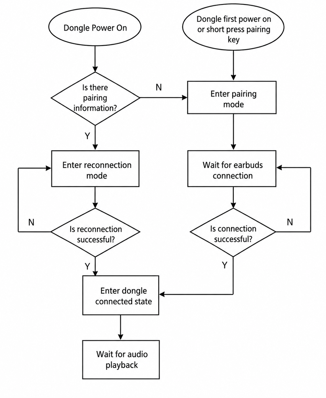
- Initialization: As shown below, in the TPSLL Audio Dongle reference design, the TPSLL Audio Dongle component is registered in the tlkapp_host_init initialization function by enabling the TLK_STK_TPD_ENABLE macro.
static void tlkapp_host_init(void)
{
tlkmw_host_init();
tlksys_task_regEvtCB(TLKSYS_TASKID_HOST,TLKSYS_TASK_EVT_HOST_HCI,tlkapp_host_hci_handler);
#if (TLK_STK_BT_ENABLE)
tlkapp_host_addModule(tlkapp_host_bt_getModule());
#endif
#if (TLK_STK_BLE_ENABLE)
tlkapp_host_addModule(tlkapp_host_le_getModule());
#endif
#if (TLK_STK_BT_TPSLL_ENABLE)
tlkapp_host_addModule(tlkapp_host_tph_getModule());
#endif
#if (TLKSTK_BTTPSLL_TWS_ENABLE)
tlkapp_host_addModule(tlkapp_host_tpt_getModule());
#endif
#if (TLK_STK_TPD_ENABLE)
tlkapp_host_addModule(tlkapp_host_tpd_getModule());
#endif
#if (TLK_STK_TPMD_ENABLE)
tlkapp_host_addModule(tlkapp_host_tpmd_getModule());
#endif
}
The core functions are as follows:
TlkAppHostModule_t* tlkapp_host_tpd_getModule(void)
{
static const TlkAppHostModuleCfg_t cfgs = {
.hostType = TLKSYS_MSG_HOST_TYPE_TPD,
.init = tlkapp_host_tpd_init,
.start = tlkapp_host_tpd_start,
.input = tlkapp_host_tpd_input,
};
static TlkAppHostModule_t module = {
.cfgs = &cfgs,
};
return &module;
}
Function: Registers the TPSLL Audio Dongle component.
static void tlkapp_host_tpd_init(void)
Function: Performs module initialization, audio path initialization, and other startup procedures.
static void tlkapp_host_tpd_start(void)
Function: Starts the power-on reconnection or pairing procedure.
static int tlkapp_host_tpd_input(uint16_t msgID, uint8_t *pData, uint16_t dataLen)
Function: Processes incoming messages.
- Dongle Pairing: The dongle enters pairing mode either when powered on for the first time or when the pairing button is pressed. In pairing mode, the dongle can pair with a new earbud and update the stored pairing information. The updated pairing information will then be used for future reconnection attempts. The relevant function is:
u8 tpd_host_dongle_start_connection_scan(void)
- Dongle Reconnection: Similar to earbud reconnection, dongle reconnection can be divided into two scenarios:
1) Power-On Reconnection: After pairing information has been successfully stored, a reconnection procedure is automatically triggered whenever the dongle is powered on again. The reconnection flow is illustrated in the figure above. Relevant function:
int tlkmdi_tpsll_audio_dongle_powerOnReconHeadset(void)
2) Reconnection After an Unexpected Disconnection: If a connection is lost due to an unexpected event, such as an unknown error or the communication distance exceeding the supported range, the dongle will initiate an automatic reconnection based on the stored pairing information. Relevant function:
static void tlkmdi_tpsll_audio_dongle_headset_disconnected_handler(uint8_t disconnect_reason)
Additional Notes:
-
Dongle pairing and reconnection use the same function interface, tpd_host_dongle_start_connection_scan. The difference lies in the connection parameters used for each scenario.
-
The dongle is unaware of master/slave role switching between the earbuds and does not need to handle or respond to such events.
BT/TPSLL Headset
Overview
This section describes the implementation of the BT/TPSLL Headset reference design in the Bluetooth Audio SDK, as well as the accompanying TPSLL Audio Dongle reference design. It also provides detailed explanations of the modules most relevant to user customization and secondary development, helping users better understand the reference design and shorten the overall development cycle from project initiation to mass production.
The BT/TPSLL Headset is a simplified version of the BT/TPSLL TWS reference design. It is derived from the dual-earbud architecture of the BT/TPSLL TWS solution and refined into a single-headset design. While retaining key performance characteristics such as high audio quality and low latency, it removes modules such as the secondary-earbud synchronization link and bidirectional communication with the charging case, resulting in a simpler and more lightweight implementation.
Typical application scenarios of the BT/TPSLL Headset reference design include:
-
Classic Bluetooth Headset Mode: The headset connects to a mobile phone or PC through Classic Bluetooth, enabling music playback and voice calls, similar to a conventional Bluetooth headset.
-
2.4 GHz Low-Latency Audio Mode (Used with a 2.4 GHz Dongle): A connection is established through a 2.4 GHz link based on the Telink Proprietary Synchronous Link Layer (TPSLL) and a 2.4 GHz dongle running the TPSLL Audio Dongle reference design. The 2.4 GHz dongle can be connected to a PC, smartphone, or tablet to provide low-latency audio transmission. This mode is particularly suitable for latency-sensitive applications such as gaming. Compared with Classic Bluetooth, TPSLL provides significant improvements in connection stability, interference resistance, operating range, power consumption, and audio codec performance.
-
Audio Mixing Mode with Concurrent Classic Bluetooth and 2.4 GHz Low-Latency Audio: While a Classic Bluetooth audio session is active, a 2.4 GHz audio stream can be connected at any time. Likewise, while a 2.4 GHz low-latency audio session is active, a Classic Bluetooth audio source can be connected simultaneously. This enables audio input from multiple devices and supports audio mixing. The design effectively resolves conflicts between different wireless audio sources while allowing users to monitor multiple audio streams simultaneously without compromising audio quality or latency.
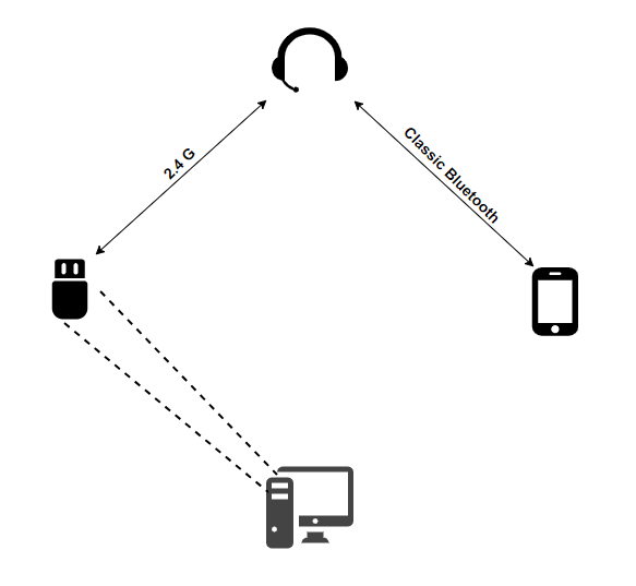
Key Features:
-
BT Features:
- Supports BT pairing and reconnection
- Supports Secure Simple Pairing (SSP) and Adaptive Frequency Hopping (AFH)
- Supports Sniff mode
- Supports WFI and Suspend modes
- Supports SBC decoding for BT music playback
- Supports CVSD and mSBC codecs for BT voice calls
- Supports BT HFP-HF, A2DP Sink, AVRCP, SPP, and GATT profiles
- Supports wireless firmware upgrades over BT SPP/GATT
- Supports audio equalization (EQ): 9-band EQ for music playback, 4-band uplink EQ for voice calls, 4-band downlink EQ for voice calls
- Supports Packet Loss Concealment (PLC) for BT voice calls
- Supports Dynamic Range Control (DRC)
- Supports Acoustic Echo Cancellation (AEC)
- Supports Noise Suppression (NS)
- Supports Beamforming (BF)
- Supports neural-network-based noise reduction for BT uplink voice calls
-
TPSLL Features:
- Supports TPSLL pairing and reconnection
- Supports LC3 Plus 48 kHz / 24-bit audio playback through the TPSLL Dongle
- Supports LC3 Plus 48 kHz / 24-bit downlink audio and 16 kHz / 24-bit uplink audio for TPSLL voice calls
- Supports low-latency audio transmission with latency as low as approximately 28 ms
- Supports Adaptive Frequency Hopping
- Supports Sniff mode
- Supports WFI and Suspend modes
-
BT and TPSLL Coexistence Features:
- Any BT use case can coexist with any TPSLL use case
- During simultaneous voice-call scenarios, only one microphone uplink path is enabled by default (BT by default), and the active uplink source can be configured
Directory Structure
bttpsll_headset
├── app_bt.c // BT ACL,profile connection, disconnection event and reconnection processing module
├── app.c // usb debug interface,tlkusb_debug_shell_hook()
├── app_config.h // Engineering configuration file
├── app_key_led_config.c // Key configuration file
└── main.c // Project entrance
System Architecture
(1) Headset Software Architecture
The software architecture of the headset is shown in the figure below. It mainly consists of the Application layer, Real-Time Operating System (RTOS), protocol layer (SDP, A2DP, HFP, AVRCP, etc.), Audio Path, HCI (the interface layer between the Host and Controller), controllers (BT controller and TPSLL controller), RF/PHY layer, and Power Manager.
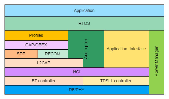
Based on the BT/TPSLL Headset reference design, this document focuses on the components required for user customization and secondary development. Some implementation principles are briefly introduced, while the Bluetooth standard protocols and the implementation details of the core libraries are beyond the scope of this document. The main topics covered are as follows:
- Headset pairing and reconnection
- Audio path on the headset side
(2) Dongle Software Architecture
The software architecture of the dongle is shown in the figure below. It mainly consists of the Application layer, Application Interface layer, Audio Path, HCI (the interface layer between the Host and Controller), TPSLL controller, RF/PHY layer, and Power Manager.
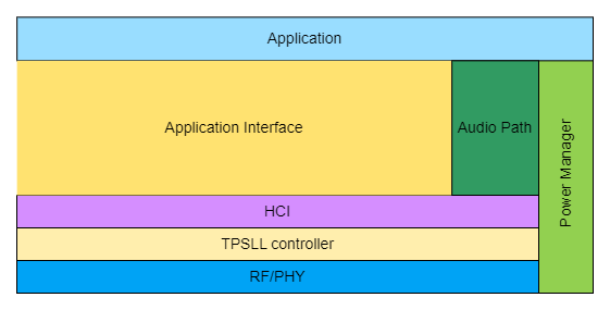
Based on the TPSLL Audio Dongle reference design, this document focuses on the components required for user customization and secondary development. Some implementation principles are briefly introduced, while the implementation details of the core libraries are beyond the scope of this document. The main topics covered are as follows:
- Pairing and reconnection between the dongle and the headset
- Audio path on the dongle side
Software Modules
(1) Headset Software Modules
In the BT/TPSLL Headset reference design, the TPSLL link also plays an important role and is responsible for pairing, reconnection, and audio data transmission. The audio link between the headset and the dongle is also established through TPSLL. The BT part is implemented based on standard Bluetooth protocols and is described in dedicated documentation; therefore, it is not discussed further here. This section mainly focuses on the upper-layer application interfaces of the TPSLL link and the BT interfaces that users need to understand.
Headset Pairing and Reconnection:
Reconnection
The reconnection procedure starts when the headset is powered on. Reconnection behaviors during pairing are not discussed here. After power-up, the headset reads the valid BT and dongle pairing information from Flash. If valid pairing information exists, the headset initiates reconnection to both the BT device and the dongle. If no valid BT pairing information is found, BT Page/Inquiry Scan is enabled for 120 seconds by default. If no valid dongle pairing information exists, the headset enters the IDLE state until it is manually powered off or pairing is triggered again.
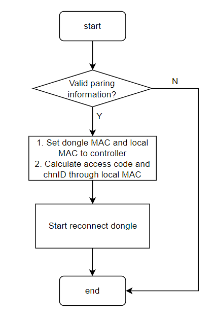
Pairing
Similar to the BT/TPSLL TWS reference design, the Headset also supports both 10-second pairing and 3-second pairing modes. In the current design, the primary difference between these two modes is whether the existing pairing information is erased.
-
3-second Pairing
- During the 3-second pairing process, the headset pages nearby dongles using a fixed Access Code and Channel ID while simultaneously enabling BT Page/Inquiry Scan. If a dongle happens to be in pairing mode and uses the same Access Code and Channel ID, the two devices can quickly discover and pair with each other within the interaction window. If a BT connection is established before the dongle connection, the headset immediately terminates the pairing procedure and switches to dongle reconnection mode, attempting to reconnect to the most recently disconnected dongle. If the dongle connection is established first, the headset resets the remaining BT Page/Inquiry Scan duration and continues waiting until
TLK_MDI_TPSLL_TPH_PAIRING_TIMEOUTexpires (30 seconds by default in the SDK). If pairing still fails after the timeout, the headset automatically enters reconnection mode and continuously attempts to reconnect to the previously disconnected dongle. If reconnection fails, the headset remains in this state until it is manually powered off or pairing is triggered again.
- During the 3-second pairing process, the headset pages nearby dongles using a fixed Access Code and Channel ID while simultaneously enabling BT Page/Inquiry Scan. If a dongle happens to be in pairing mode and uses the same Access Code and Channel ID, the two devices can quickly discover and pair with each other within the interaction window. If a BT connection is established before the dongle connection, the headset immediately terminates the pairing procedure and switches to dongle reconnection mode, attempting to reconnect to the most recently disconnected dongle. If the dongle connection is established first, the headset resets the remaining BT Page/Inquiry Scan duration and continues waiting until
-
10-second Pairing
- During the 10-second pairing process, the headset first erases the BT and dongle pairing information stored in Flash and then pages nearby dongles using a fixed Access Code and Channel ID. The subsequent procedure is identical to that of 3-second pairing. If pairing still fails after the timeout, the headset enters the IDLE state and remains there until the user manually powers it off or triggers pairing again.
// Both 3s and 10s paring use the following Access Code and Channel ID
#define TPH_HOST_DONGLE_SETUP_COMMON_ACCESSCODE 0x56291435
#define TPH_HOST_DONGLE_SETUP_COMMON_CHN 0x12
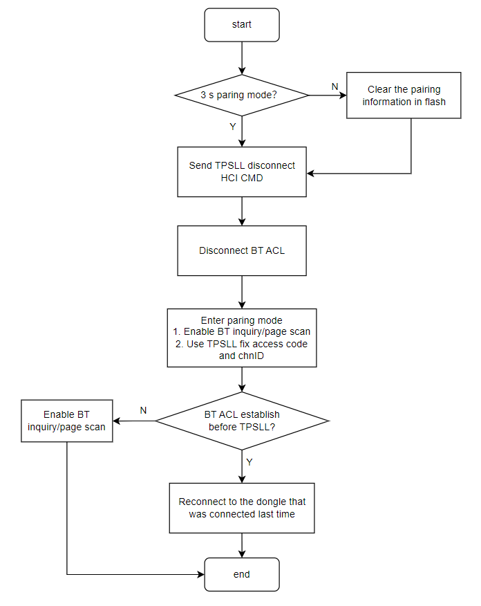
According to the flow described above, the implementation principles and function interfaces are introduced as follows:
- Initialization: The entire Bluetooth Audio SDK adopts a modular design. Before invoking underlying components, the upper-layer application first initializes the corresponding modules.
static void tlkapp_host_init(void)
{
tlkmw_host_init();
tlksys_task_regEvtCB(TLKSYS_TASKID_HOST,TLKSYS_TASK_EVT_HOST_HCI,tlkapp_host_hci_handler);
#if (TLK_STK_BT_ENABLE)
tlkapp_host_addModule(tlkapp_host_bt_getModule());
#endif
...
#if (TLK_STK_BT_TPSLL_ENABLE)
tlkapp_host_addModule(tlkapp_host_tph_getModule());
#endif
#if (TLK_STK_TPD_ENABLE)
tlkapp_host_addModule(tlkapp_host_tpd_getModule());
#endif
...
}
As shown in the code above, the BT/TPSLL Headset reference design registers the headset functional module by enabling the TLK_STK_BT_TPSLL_ENABLE macro.
TlkAppHostModule_t* tlkapp_host_tph_getModule(void)
{
static const TlkAppHostModuleCfg_t cfgs = {
.hostType = TLKSYS_MSG_HOST_TYPE_TPH,
.init = tlkapp_host_tph_init,
.handler = tlkapp_host_tph_handler,
.input = tlkapp_host_tph_msgHandle,
};
static TlkAppHostModule_t module = {
.cfgs = &cfgs,
};
return &module;
}
As shown in the code above, the registration of the headset module mainly consists of a hostType identifier and three callback functions:
hostType = TLKSYS_MSG_HOST_TYPE_TPH
Function: Declares the identity code of this module (TLKSYS_MSG_HOST_TYPE_TPH) to the host thread. All system threads (host, system, audio, lemgr, and user) use this identifier for message routing. The receiver only processes event packets whose hostType matches its own and handles them through tlkapp_host_tph_msgHandle(). In essence, this identifier acts as the module's address on the global message bus, ensuring that the initialization, execution, and communication of the TPH component are isolated from other services.
static void tlkapp_host_tph_init(void)
Function: Initializes the upper-layer application interfaces of the headset, including state machine initialization, multi-core communication initialization, and pairing parameter initialization.
static void tlkapp_host_tph_handler(void)
Function: Drives the state machine and manages transitions between pairing and reconnection states.
int tlkapp_host_tph_msgHandle(uint16 msgID, uint08 *pData, uint16 dataLen)
Function: Processes messages and is tightly coupled with hostType. Different events, most of which are triggered by key operations, are processed according to the message type. Different key combinations generate different messages and trigger corresponding event handling procedures.
int tlkapp_host_tph_msgHandle(uint16_t msgID, uint8_t *pData, uint16_t dataLen)
{
(void) msgID;
(void) pData;
(void) dataLen;
switch(msgID){
case TLKSYS_TPH_MSGID_3S_PAIR:
tlkmdi_bt_tph_pair_start(false);
break;
case TLKSYS_TPH_MSGID_10S_PAIR:
tlkmdi_bt_tph_pair_start(true);
break;
case TLKSYS_TPH_MSGID_SEND_KEY:
return tlkapp_host_tph_recvSendKeyDeal(pData,dataLen);
default:
return -TLK_ENOSUPPORT;
}
return TLK_ENONE;
}
- Entering Pairing Mode: Double-clicking or triple-clicking the pairing key enters pairing mode. Through the key scanning module (described in detail in the SDK Common Components section), the pairing message is routed to this module, which then invokes the pairing function to enter pairing mode.
void tlkmdi_bt_tph_pair_start(bool isRefactory)
The parameter isRefactory indicates the link establishment mode. A value of true represents 10-second pairing, while false represents 3-second pairing. Although several link establishment modes are provided by this reference design, the current headset implementation only uses TPH_HOST_DONGLE_SETUP_MODE_CC_HEADSET.
typedef enum
{
TPH_HOST_HEADSET_SETUP_MODE_IDLE,
TPH_HOST_HEADSET_SETUP_MODE_NORMAL,
TPH_HOST_HEADSET_SETUP_MODE_3S,
TPH_HOST_HEADSET_SETUP_MODE_10S,
TPH_HOST_DONGLE_SETUP_MODE_NORMAL,
TPH_HOST_DONGLE_SETUP_MODE_PAIRING,
TPH_HOST_DONGLE_SETUP_MODE_CC_HEADSET,
} tph_headset_setup_mode_for_host_e;
Once either pairing mode successfully establishes a connection with the dongle, the system sequentially triggers the TPSLL_EVTID_DONGLE_MAC_UPDATE and TPSLL_EVTID_DONGLE_CONNECT events. Their callback functions are responsible for saving dongle pairing information, writing the peer MAC address to the TPSLL controller, updating the dongle connection status, and synchronizing prompt tones and LED indications.
static int tlkmdi_bt_tph_dongle_macUpdateHandler(uint8_t *pData, uint16_t dataLen)
static int tlkmdi_bt_tph_dongle_connectHandler(uint8_t *pData, uint16_t dataLen)
- State Machine Transitions (State Transition): This state machine is the core scheduler for pairing and reconnection in the BT/TPSLL Headset reference design and adopts a run-to-completion model. tlkmdi_bt_tph_pairing_handler() is invoked during each system loop iteration. As long as any state handler returns true, the scheduler immediately re-enters and continues execution until no further state transitions occur, ensuring that all continuous processing steps are completed within a single scheduling cycle.
int tlkmdi_bt_tph_pairing_handler(void)
- State Overview
| State Macro | Description |
|---|---|
| TLKMDI_TPSLL_PAIRING_ASYNC_DISCONNECTED | The dongle link has been disconnected |
| TLKMDI_TPSLL_PAIRING_BT_DSICON_WAITING | Waiting for the BT ACL link to disconnect |
| TLKMDI_TPSLL_PAIRING_BT_DISCONNECTED | The BT ACL link has been disconnected, and the device enters discoverable/pairing mode |
| TLKMDI_TPSLL_PAIRING_CONNECT_WAITING | Scanning/paging has started, and the system is waiting for a dongle connection |
| TLKMDI_TPSLL_IDLE | Idle state after power-on or reconnection failure |
- Operating Principle
The "single-step atomic" design requires each tlkmdi_bt_tph_nowPSM_xxx() function to perform only one operation, such as issuing an HCI command or updating a state variable, and then return true to request immediate rescheduling. Returning false, or entering a state outside the scope of state machine scheduling, immediately stops the state machine and transitions it into the IDLE state until it is triggered again.
In practical applications, abnormal reconnection scenarios can be classified into the following categories:
- Abnormal Disconnection Between the Headset and Dongle: When the headset and dongle are disconnected because of unknown errors or out-of-range conditions, both devices initiate reconnection and remain in the reconnection state until reconnection succeeds or the user manually triggers pairing.
- Abnormal Disconnection Between the Headset and Mobile Phone: When the headset and mobile phone are disconnected because of unknown errors or out-of-range conditions, the headset automatically initiates reconnection.
The following interfaces are mainly involved:
static int tlkmdi_bt_tph_dongle_disconnHandler(uint8_t *pData, uint16_t dataLen)
Function: In the disconnection event callback, updates prompt tones and LED indications and triggers different operations according to the current state machine state.
void tlkmdi_bt_tph_dongle_reconnStart(void)
Function: Initiates the reconnection procedure between the headset and the dongle.
(2) Dongle Software Modules
This module has already been introduced in the BT/TPSLL TWS section. Its principles and mechanisms are identical to those of the TWS reference design and therefore will not be described again.
LE example Demo
Overview
The BLE Example project adopts a unified configuration and modular management framework, enabling developers to quickly verify functionalities, evaluate features, and create different single-BLE application examples. The project uses the app_example.h file to configure different application examples and implement user-layer functionalities.
Supported Hardware
Currently, the project supports the following hardware platforms:
| MCU Series | Board Model |
|---|---|
| TL721x | C1TXA104_V1.1(CODEC1-V2) C1T315A20 C1T315A20_V2 |
| TLSR952x | C1T266A20_V1.3 |
| TL751x | C1T368A20_V1_1 |
| TL322x | C1T371A20_V1_1 C1T379A20_V1_0 |
Directory Structure
vendor/ble_example/
├── app_example.h # Project management
├── app_config.h # Common project configurations
├── app_create_new_demo/ # Application example directory
│ ├── app_create_new_demo.c # Application example source code
│ ├── app_create_new_demo_cfg.h # Application-specific configurations
│ └── README.md # Application documentation
├── app_key.c # Key handling functions
├── app_key.h
└── main.c # Project entry
(1) main.c
main.c is the entry point of the project and mainly performs the following tasks:
-
System initialization, including the initialization of basic system resources such as system timers, system events, and system tasks.
-
System startup, including the initialization of the Bluetooth protocol stack, starting the main loop of the Bluetooth protocol stack, and launching other system tasks.
-
Entering the main system loop, where system events, including timer events and other system events, are continuously processed.
As shown in the code below, different application examples are selected through the APP_DEMO_SELECT macro to implement different functionalities.
int INIT(APP_DEMO_SELECT)(void);
void tlkapp_host_le_init(void)
{
ble_stack_init();
INIT(APP_DEMO_SELECT)();
}
int START(APP_DEMO_SELECT)(void);
void tlkapp_host_le_start(void)
{
START(APP_DEMO_SELECT)();
}
int main(void)
{
tlksys_init();
tlksys_start(tlkapp_create_allTasks);
#if (!TLK_CFG_RTOS_ENABLE)
while (1) {
#if (BLE_CONTROLLER_INITIAL_EN)
tlksdk_main_loop();
#endif
tlksys_handler();
}
#endif
return 0;
}
(2) app_key.h and app_key.c
app_key.h and app_key.c implement key processing functions. Users can register key callback functions according to their requirements. When a key is pressed, the corresponding callback function is invoked.
The default Key ID definitions are as follows:
| Key ID | Description | Key ID | Description |
|---|---|---|---|
| 0 | Key 1 click | 4 | Key 1 double click |
| 1 | key 2 click | 5 | Key 2 double click |
| 2 | Key 3 click | 6 | Key 3 double click |
| 3 | Key 4 click | 7 | Key 4 double click |
Users can modify the key definitions as required and can also implement custom key processing functions in app_key.c.
/**
* @brief Register a callback function for a specific key.
*
* @param[in] key_id Key ID.
* @param[in] callback Callback function to be called when the key is pressed.
*
* @return void
*/
void app_key_register_callback(uint8_t key_id, void (*callback)(void));
(3) app_config.h
app_config.h defines the common configurations of the project, including basic system configurations, basic Bluetooth protocol stack configurations, and general application configurations. Under normal circumstances, users do not need to modify this file.
(4) app_example.h
app_example.h provides a unified management framework for the entire project. Users can select different application examples according to their requirements, and each application example can define its own specific configurations to support different application scenarios.
The core implementation is shown in the following code snippet. The file provides three macros—START, INIT, and IS_DEMO_SELECTED—and defines dedicated macros for each application example, such as APP_BLE_NEW_DEMO, APP_BLE_ADV, and APP_BLE_ACL.
#define START(...) EXPAND(START_(__VA_ARGS__))
#define INIT(...) EXPAND(INIT_(__VA_ARGS__))
#define IS_DEMO_SELECTED(...) (GET_DEMO_ID(APP_DEMO_SELECT) == GET_DEMO_ID(__VA_ARGS__))
//
#define APP_BLE_NEW_DEMO app_new_demo, 1
// Simple BLE demo
#define APP_BLE_ADV app_adv, 100
#define APP_BLE_ACL app_acl, 101
// develop can not commit this select to gitlab.
#define APP_DEMO_SELECT APP_BLE_NEW_DEMO
- INIT: Initialization function. This function is called during system initialization and is mainly used to configure application-specific Bluetooth protocol stack settings.
- START: Startup function. This function is called during system startup and is mainly responsible for starting the Bluetooth controller and launching the selected application example.
- IS_DEMO_SELECTED: Determines whether a specific application example has been selected. Based on APP_DEMO_SELECT and the specified application example macro, it determines whether the corresponding demo is enabled. This mechanism is primarily used by common features shared across multiple application examples. For example, tlkusb_debug_shell_hook is an SDK common feature that may be required by multiple demos and therefore uses this macro for conditional inclusion.
- APP_BLE_NEW_DEMO: Application example macro that defines a new application example. It mainly consists of the demo name and a unique ID. The ID is used by IS_DEMO_SELECTED and must remain unique.
- APP_DEMO_SELECT: Specifies the currently selected application example. In main.c, the corresponding application example is compiled and executed according to this macro.
The START, INIT, and IS_DEMO_SELECTED macros are implemented through macro expansion. For implementation details, please refer to the source code or consult AI-based code analysis tools.
#if __has_include(CFG_PATH(APP_DEMO_SELECT))
#include CFG_PATH(APP_DEMO_SELECT)
#endif
#define STRINGIFY_HELPER(x) #x
#define STRINGIFY(x) STRINGIFY_HELPER(x)
#define START(...) EXPAND(START_(__VA_ARGS__))
#define INIT(...) EXPAND(INIT_(__VA_ARGS__))
#define IS_DEMO_SELECTED(...) (GET_DEMO_ID(APP_DEMO_SELECT) == GET_DEMO_ID(__VA_ARGS__))
#define CAT(a, b) a##b
#define EXPAND(x) x
#define EVAL(x) EXPAND(x)
#define TOSTRING(x) STRINGIFY(x)
#define CFG_PATH_(x, id) TOSTRING(EVAL(CAT(x/x,_cfg.h)))
#define CFG_PATH(...) EXPAND(CFG_PATH_(__VA_ARGS__))
#define INIT_(x, id) EVAL(CAT(x, _init))
#define START_(x, id) EVAL(CAT(x, _start))
#define GET_DEMO_ID_(x, id) id
#define GET_DEMO_ID(...) GET_DEMO_ID_(__VA_ARGS__)
(5) app_create_new_demo/
The app_create_new_demo/ directory provides several application examples that can be used as templates for creating custom BLE applications. Developers can create different application examples according to their requirements and implement their own functionalities.
Note
- If a demo requires a dedicated configuration file, the folder name must be identical to the demo macro name, and the configuration file name must end with _cfg.h. Refer to the implementation in app_example.h for details.
#include "stack/ble/ble.h"
#include "../app_example.h"
int INIT(APP_BLE_NEW_DEMO)(void)
{
tlk_printf("Hello, Telink BLE Demo initialized!");
return 0;
}
void START(APP_BLE_NEW_DEMO)(void)
{
tlk_printf("Hello, Telink BLE Demo started!");
}
Each demo must implement two functions, INIT() and START(). INIT() is called during system initialization. START() is called after the system startup is complete. For example, the APP_BLE_NEW_DEMO example simply prints initialization and startup information.
Create a New Application Demo
(1) Register the Demo in app_example.h
Define the Demo Macro:
Add a new demo macro definition in the Demo definition section of app_example.h:
#define APP_BLE_MY_DEMO app_my_demo, 500
Format Description:
APP_BLE_MY_DEMO: Macro name of the demo (uppercase naming is recommended).app_my_demo: Actual demo name (match the folder name).500: Unique demo ID (make sure it does not conflict with existing demo IDs).
Demo ID Allocation Rules:
- Generic BLE Demo: 100-199
- LE Audio Demo: 200-299
- Customer-specific Demo: 1000-1099
Select APP_BLE_MY_DEMO:
Modify the APP_DEMO_SELECT macro to point to the newly created demo:
#define APP_DEMO_SELECT APP_BLE_MY_DEMO
(2) Create the app_my_demo Folder
Create a folder named app_my_demo under vendor/ble_example
vendor/ble_example/app_my_demo/
Note
- The folder name is recommended to consist of lowercase letters and underscores.
- The folder name will be used as the demo identifier.
(3) Create New Files
Create the following files in the newly created app_my_demo folder:
Main Implementation File (Required)
- File name:
{demo_name}.c - Example:
app_my_demo.c - Purpose: Implements the main functionality of the demo.
Configuration File (Optional)
- File name:
{demo_name}_cfg.h - Example:
app_my_demo_cfg.h - Purpose: Configures protocol stack parameters and demo-specific options.
Documentation File (Optional)
- File name:
README.md - Purpose: Documents the demo functionality and usage instructions.
Implement Basic Functions
The following two functions must be implemented in the main source file of the demo:
#include "stack/ble/ble.h"
#include "../app_example.h"
// Initialization Function
int INIT(APP_BLE_MY_DEMO)(void)
{
// Initialize resources required by the demo
tlk_printf("My Demo initialized!");
return 0; // Return 0 on success
}
// Startup Function
void START(APP_BLE_MY_DEMO)(void)
{
// Entry point of the demo
tlk_printf("My Demo started!");
// Start the demo here, such as enabling scanning or advertising
}
Function Description:
INIT()Function: Called during system initialization and used to initialize resources required by the demo.- Return value:
0indicates success, any non‑zero value indicates failure
- Return value:
START()Function: Called after initialization is complete; this is the main entry point for the demo.
Macro Expansion Mechanism:
INIT(APP_BLE_MY_DEMO)is automatically expanded toapp_my_demo_init()START(APP_BLE_MY_DEMO)is automatically expanded toapp_my_demo_start()
Compiling and Running
After completing the steps above, you can compile and run the newly created APP_BLE_MY_DEMO:
(1) Ensure that APP_DEMO_SELECT in app_example.h points to the new demo
(2) Compile the project
(3) Download the firmware to the device
(4) Run the app and verify its functionality
Description of the Included Sample Demos
The project provides numerous sample demos to help users quickly test and use the software. Below is a description of the features of each demo:
BLE New Demo:
Provides an empty BLE application template that can be used to verify the basic functionality of the platform and chip. It is equivalent to a classic "Hello World" example.
BLE ADV Demo:
Implements traditional broadcast functionality and can be used to verify the effectiveness of traditional broadcasts.
BLE ACL Demo:
Implements BLE ACL functionality; this all-in-one BLE device can establish master-slave communication with a smartphone.
BLE ACL Peripheral Demo:
Implements BLE ACL Peripheral functionality and can be used to verify the functionality of BLE Peripheral devices.
BLE ACL Central Demo:
Implements BLE ACL Central functionality and can be used to verify the functionality of BLE Central devices.
BLE OTA Demo:
Implements BLE OTA functionality and can be used to verify BLE OTA upgrade capabilities.
BLE SMP Demo:
Implements BLE SMP functionality and can be used to verify BLE SMP encryption capabilities. This demo is an extension of BLE ACL and can verify different SMP encryption methods.
BLE Random Address Demo:
Implements BLE Random Address functionality and can be used to verify the functionality of BLE static random addresses, resolvable random addresses, and non-resolvable random addresses.
BLE HID Device Demo:
Implements BLE HID Device functionality and integrates BLE Keyboard and BLE Mouse; it can be used to verify the functionality of BLE HID devices.
BLE Scan Demo:
Implements BLE scan functionality, including traditional and extended scans, and can be used to verify BLE scan capabilities.
BLE SPP Server Demo:
Implements BLE SPP server functionality and can be used to verify BLE SPP server capabilities.
BLE SPP Client Demo:
Implements BLE SPP client functionality and can be used to verify BLE SPP client capabilities.
BLE SSDP Demo:
This demo implements the functionality of BLE SSDP (Simple Service Discovery Protocol) and can be used to verify BLE SSDP functionality. It has the same functionality as the BLE SPP Client Demo, but calls different APIs.
BLE iOS ANCS Demo:
This demo implements the functionality of BLE iOS ANCS (Apple Notification Center Service). The application provides a method to determine whether the device is an iOS device and allows users to subscribe to iOS notifications.
LE Audio Unicast Server Demo:
This demo implements the functionality of an LE Audio Unicast Server. It can be used to verify LE Audio unicast functionality and enables LE Audio playback with LE Audio-compatible smartphones.
LE Audio Unicast Client Demo:
This demo implements the functionality of an LE Audio Unicast Client and can be used to verify LE Audio unicast capabilities. It can work with an LE Audio Unicast Server to enable LE Audio playback, including music playback, two-way calls, and single-microphone functionality.
LE Audio Source Demo:
Implements the functionality of an LE Audio Source. As a standard LE Audio unicast client, it can play audio—including music and two-way calls—via a host computer in conjunction with standard LE Audio devices.
LE Audio Auracast(Broadcast) Source Demo:
Implements the functionality of an LE Audio Auracast (Broadcast) Source and can be used to verify LE Audio broadcast capabilities.
LE Audio Auracast(Broadcast) Sink Demo:
This demo implements the functionality of an LE Audio Auracast (Broadcast) Sink. It can be used to verify LE Audio broadcast reception capabilities and can be tested in conjunction with an LE Audio Auracast (Broadcast) Source.
LE Audio Device Demo:
This demo implements the functionality of an LE Audio Device and includes both Unicast Server and Auracast (Broadcast) Sink capabilities. It can be used with LE Audio-enabled smartphones to demonstrate all LE Audio features.
LE Audio Path
The LE Audio Path (hereinafter referred to as the LEA audio path) is implemented based on the current SDK’s audio path architecture, primarily to test whether LE Audio functions are working properly and to provide a reference implementation.
The primary design objectives of the LEA audio path are to provide an audio path architecture that is highly compatible, relatively feature-complete, highly scalable, and highly reliable. Audio metrics such as audio link latency are not included in the general design objectives; therefore, the design objectives of the LEA audio path are primarily focused on meeting the requirements of audio applications. The development of LE Audio-related projects requires optimizing the audio path design to meet the needs of audio applications.
(1) Architecture Design
The LE Audio architecture is divided into three parts:
-
Audio Path Tasks: Including Unicast Client(tlkmdi_lea_uc.c),Unicast Server(tlkmdi_lea_us.c),Broadcast Source(tlkmdi_leg_bms.c) and Broadcast Sink(tlkmdi_leg_bmr.c).
-
Common Audio Path: Including data processing for both audio input (Audio Input) and audio output (Audio Output).
-
Audio Driver Module: Mainly encapsulates audio drivers, including audio input and audio output.
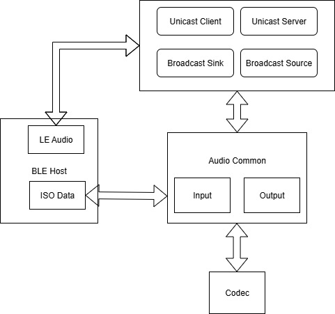
The architecture of LE Audio is shown in the figure above. Audio Common is responsible for audio input and output processing, including LC3 codec initialization, audio data encoding and decoding, and synchronized audio playback processing.
The Codec module encapsulates and abstracts unified audio interfaces for different audio input and output methods, such as UAC, Codec, A2DP In, and Sine Wave.
Specific audio task modules are developed based on the audio path framework of the current SDK. The SDK currently supports four typical LE Audio tasks: Unicast Client, Unicast Server, Broadcast Source, and Broadcast Sink.
(2) Codec Module
The logic block diagram of the Codec module is shown below. It mainly instantiates different audio inputs into unified audio interfaces and provides interfaces for Codec opening, closing, audio data acquisition, and audio data transmission.
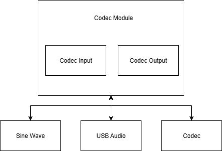
Opening the Codec Module:
The initialization interfaces of the Codec module are mainly divided into Input and Output parts, corresponding to audio input and audio output, respectively.
-
Input Stream Initialization: The is_input_stream_init field indicates whether the audio input stream is initialized. true indicates that the Input Stream is initialized, while false indicates that it is not initialized. input_sample_rate indicates the audio input sample rate and directly uses the parameters defined by the LE Audio specification. input_location indicates the audio input location. Currently, only left-channel audio, right-channel audio, and stereo audio configurations are supported.
-
Output Stream Initialization: The is_output_stream_init field indicates whether the audio output stream is initialized. true indicates that the Output Stream is initialized, while false indicates that it is not initialized. output_sample_rate indicates the audio output sample rate and directly uses the parameters defined by the LE Audio specification. output_location indicates the audio output location. Currently, only left-channel audio, right-channel audio, and stereo audio configurations are supported.
/**
* @brief LE Audio Codec configuration structure.
*/
struct lea_codec_config {
bool is_input_stream_init;
bool is_output_stream_init;
uint8_t input_sample_rate;
uint32_t input_location;
uint8_t output_sample_rate;
uint32_t output_location;
};
/**
* @brief Initialize LE Audio codec stream.
* @param[in] config - pointer to the codec configuration structure.
* @return none.
*/
void lea_codec_stream_init(struct lea_codec_config *config);
The audio sample rate parameters currently support only 8 kHz, 16 kHz, 24 kHz, 32 kHz, and 48 kHz. The specific sample rate definitions are as follows:
// Audio Frame Frequency (for codec parameter)
enum lea_select_sampling_freq {
LEA_SELECT_SAMPLING_FREQ_MIN, /** < Minimum value for audio sampling frequency selection */
LEA_SELECT_SAMPLING_FREQ_8000_HZ = 1, /** < 8000 Hz */
LEA_SELECT_SAMPLING_FREQ_11025_HZ = 2, /** < 11025 Hz */
LEA_SELECT_SAMPLING_FREQ_16000_HZ = 3, /** < 16000 Hz */
LEA_SELECT_SAMPLING_FREQ_22050_HZ = 4, /** < 22050 Hz */
LEA_SELECT_SAMPLING_FREQ_24000_HZ = 5, /** < 24000 Hz */
LEA_SELECT_SAMPLING_FREQ_32000_HZ = 6, /** < 32000 Hz */
LEA_SELECT_SAMPLING_FREQ_44100_HZ = 7, /** < 44100 Hz */
LEA_SELECT_SAMPLING_FREQ_48000_HZ = 8, /** < 48000 Hz */
LEA_SELECT_SAMPLING_FREQ_88200_HZ = 9, /** < 88200 Hz */
LEA_SELECT_SAMPLING_FREQ_96000_HZ = 10, /** < 96000 Hz */
LEA_SELECT_SAMPLING_FREQ_176400_HZ = 11, /** < 176400 Hz */
LEA_SELECT_SAMPLING_FREQ_192000_HZ = 12, /** < 192000 Hz */
LEA_SELECT_SAMPLING_FREQ_384000_HZ = 13, /** < 384000 Hz */
LEA_SELECT_SAMPLING_FREQ_MAX, /** < Maximum value for audio sampling frequency selection */
};
The audio output location parameters currently support only LEA_LOCATION_FRONT_LEFT, LEA_LOCATION_FRONT_RIGHT, and LEA_LOCATION_FRONT_LEFT | LEA_LOCATION_FRONT_RIGHT. The specific definitions are as follows:
/** < LE Audio Location Definitions */
enum lea_location_flag {
LEA_LOCATION_NONE = 0x0000,
LEA_LOCATION_FRONT_LEFT = 1U << 0, /** < Front Left */
LEA_LOCATION_FRONT_RIGHT = 1U << 1, /** < Front Right */
LEA_LOCATION_FRONT_CENTER = 1U << 2, /** < Front Center */
LEA_LOCATION_LOW_FREQUENCY_1 = 1U << 3, /** < Low Frequency Effects 1 */
LEA_LOCATION_BACK_LEFT = 1U << 4, /** < Back Left */
LEA_LOCATION_BACK_RIGHT = 1U << 5, /** < Back Right */
LEA_LOCATION_FRONT_LEFT_OF_CENTER = 1U << 6, /** < Front Left of Center */
LEA_LOCATION_FRONT_RIGHT_OF_CENTER = 1U << 7, /** < Front Right of Center */
LEA_LOCATION_BACK_CENTER = 1U << 8, /** < Back Center */
LEA_LOCATION_LOW_FREQUENCY_2 = 1U << 9, /** < Low Frequency Effects 2 */
LEA_LOCATION_SIDE_LEFT = 1U << 10, /** < Side Left */
LEA_LOCATION_SIDE_RIGHT = 1U << 11, /** < Side Right */
LEA_LOCATION_TOP_FRONT_LEFT = 1U << 12, /** < Top Front Left */
LEA_LOCATION_TOP_FRONT_RIGHT = 1U << 13, /** < Top Front Right */
LEA_LOCATION_TOP_FRONT_CENTER = 1U << 14, /** < Top Front Center */
LEA_LOCATION_TOP_CENTER = 1U << 15, /** < Top Center */
LEA_LOCATION_TOP_BACK_LEFT = 1U << 16, /** < Top Back Left */
LEA_LOCATION_TOP_BACK_RIGHT = 1U << 17, /** < Top Back Right */
LEA_LOCATION_TOP_SIDE_LEFT = 1U << 18, /** < Top Side Left */
LEA_LOCATION_TOP_SIDE_RIGHT = 1U << 19, /** < Top Side Right */
LEA_LOCATION_TOP_BACK_CENTER = 1U << 20, /** < Top Back Center */
LEA_LOCATION_BOTTOM_FRONT_CENTER = 1U << 21, /** < Bottom Front Center */
LEA_LOCATION_BOTTOM_FRONT_LEFT = 1U << 22, /** < Bottom Front Left */
LEA_LOCATION_BOTTOM_FRONT_RIGHT = 1U << 23, /** < Bottom Front Right */
LEA_LOCATION_FRONT_LEFT_WIDE = 1U << 24, /** < Front Left Wide */
LEA_LOCATION_FRONT_RIGHT_WIDE = 1U << 25, /** < Front Right Wide */
LEA_LOCATION_LEFT_SURROUND = 1U << 26, /** < Left Surround */
LEA_LOCATION_RIGHT_SURROUND = 1U << 27, /** < Right Surround */
LEA_LOCATION_RESERVED = ((1U << 28) | (1U << 29) | (1U << 30) | (1U << 31)) /** < bit28 ~ bit29 */
};
Closing the Codec Module:
The Codec module closing interface is mainly used to release resources occupied by the Codec module.
/**
* @brief Deinitialize LE Audio codec stream.
* @return none.
*/
void lea_codec_stream_deinit(void);
(3) Setting the Codec Output Volume
The Codec module provides an interface for setting the output volume, which is mainly used to configure the audio output volume.
/**
* @brief Set output volume.
* @param[in] volume - volume value to set.
* @return none.
*/
void lea_codec_set_output_volume(uint8_t volume)
Definitions of Different Codec Instances:
The Codec module defines several different instances by default, corresponding to different audio input and output methods. The SDK currently supports Codec (corresponding to different hardware Codec drivers on different chips or modules), USB Audio (USB audio devices, requiring UAC functionality to be enabled in the demo), and Sine Wave (generates audio signals for testing audio playback functionality and supports input only).
#define LE_AUDIO_CODEC_TYPE_NONE 0x00
#define LE_AUDIO_CODEC_TYPE_CODEC 0x01
#define LE_AUDIO_CODEC_TYPE_USB_AUDIO 0x02
#define LE_AUDIO_CODEC_SAMPLE_SINE_WAVE 0x03
#ifndef LE_AUDIO_CODEC_INPUT_TYPE
#define LE_AUDIO_CODEC_INPUT_TYPE LE_AUDIO_CODEC_TYPE_NONE
#endif
#ifndef LE_AUDIO_CODEC_OUTPUT_TYPE
#define LE_AUDIO_CODEC_OUTPUT_TYPE LE_AUDIO_CODEC_TYPE_NONE
#endif
Users can modify the definition of LE_AUDIO_CODEC_INPUT_TYPE to change the Input type and modify the definition of LE_AUDIO_CODEC_OUTPUT_TYPE to change the Output type as needed.
Input-Related Instance Interfaces:
The audio input interface clears all currently unprocessed input data and discards the pending data.
/**
* @brief Clean input buffer.
* @return none.
*/
void lea_codec_input_clean_buffer(void);
Enable and disable audio input.
/**
* @brief Initialize input stream.
* @return none.
*/
void lea_codec_input_stream_init(void);
/**
* @brief Deinitialize input stream.
* @return none.
*/
void lea_codec_input_stream_deinit(void);
Determine the number of unprocessed audio samples currently available. If sufficient data exists, write the data into the Left and Right audio data buffers, respectively.
The sample count is related only to the audio sample rate and is independent of the audio sample depth and the number of audio channels.
/**
* @brief Get input audio data.
* @param[out] left_data - pointer to left channel audio data buffer.
* @param[out] right_data - pointer to right channel audio data buffer.
* @param[in] sample_num - number of samples per channel to read.
* @return true if data is successfully read, false otherwise.
*/
bool lea_codec_input_get_audio_data(int16_t *left_data, int16_t *right_data, uint16_t sample_num);
Output-Related Instance Interfaces:
Enable and disable audio output.
/**
* @brief Initialize output stream.
* @return none.
*/
void lea_codec_output_stream_init(void);
/**
* @brief Deinitialize output stream.
* @return none.
*/
void lea_codec_output_stream_deinit(void);
Set the audio output data by writing a specified number of samples into the audio output buffer. Left Data represents the left-channel audio data, Right Data represents the right-channel audio data, and Sample Num represents the number of samples.
/**
* @brief Set output audio data.
* @param[in] left_data - pointer to left channel audio data.
* @param[in] right_data - pointer to right channel audio data.
* @param[in] sample_num - number of samples per channel.
* @return none.
*/
void lea_codec_output_set_audio_data(int16_t *left_data, int16_t *right_data, uint16_t sample_num);
(4) Common Input and Output Instance Interface
Only when LE_AUDIO_CODEC_INPUT_TYPE and LE_AUDIO_CODEC_OUTPUT_TYPE select the same audio instance, and the audio task enables both input and output simultaneously, a common initialization interface is provided to accommodate Codec instances that do not support separate initialization for input and output.
/**
* @brief Initialize both input and output streams.
* @return none.
*/
void lea_codec_in_output_stream_init(void);
/**
* @brief Deinitialize both input and output streams.
* @return none.
*/
void lea_codec_in_output_stream_deinit(void);
(5) Audio Common Module
This module mainly abstracts audio application scenarios into two directions: audio input and audio output. From different perspectives or dimensions, audio input and audio output may appear as mirrored counterparts.
Note
- In the current SDK, the unified logic is as follows: capturing raw audio from an external Codec, encoding it with the LC3 encoder, and transmitting it through the LE Audio protocol is defined as audio input; receiving encoded data through the LE Audio protocol, decoding it with the LC3 decoder, and playing it through the external Codec is defined as audio output.
Four typical audio scenarios are supported:
- Broadcast Source: A broadcast source that only captures and transmits audio. Therefore, it only provides audio input functionality.
- Broadcast Sink: A broadcast receiver that only receives and plays BIS audio. Therefore, it only provides audio output functionality.
- Unicast Client: A unicast client. In the music playback scenario, it only provides audio input functionality for connected devices. In the bidirectional call scenario, it provides both audio input and audio output functionality. In the one-way microphone audio capture scenario, it only provides audio output functionality.
- Unicast Server: A unicast server whose logic is exactly the opposite of the Unicast Client. For example, in the music playback scenario, it only provides audio output functionality.
The logic diagram of the Audio Common module is shown below:
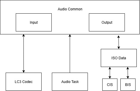
Different Audio Tasks configure the audio functions and parameters for the current audio scenario through a set of APIs. Based on the configuration, the Audio Common module initializes the corresponding LC3 encoders/decoders and receives or transmits encoded audio data through the ISO Data module.
The structure definition of the LE Audio parameters is as follows:
blocks: Number of LC3 encoder blocks. Currently, only 1 is supported.
location: Audio location information used to identify the audio position. Currently, only left channel (0x01), right channel (0x02), and stereo (0x03) are supported.
samplingFrequency: Audio sampling frequency.
frameDuration: LC3 encoder frame duration. Currently, only 10 ms (0x01) and 7.5 ms (0x02) are supported.
frameOctets: LC3 encoder frame size, in bytes.
iso_handle: Handle of the ISO Data module, used to identify the current ISO Data handle.
presentationDelay: Playback delay, in microseconds. Currently, it is only used for output.
struct lea_config { // refer to struct lea_bmr_config,
uint8_t blocks;
uint32_t location;
uint8_t samplingFrequency;
uint8_t frameDuration;
uint16_t frameOctets;
uint16_t iso_handle;
uint32_t presentationDelay;
};
Input Interfaces:
Initialize the configuration information related to Input, which is mainly used internally by the Audio Common module.
/**
* @brief Initialize LE Audio input configuration cache.
* @return none.
*/
void lea_input_config_initial(void);
Configure and release the configuration information related to Input. This must be completed before calling lea_set_input_config(). It is mainly used to allocate the number of LC3 encoders/decoders and the required memory.
/**
* @brief Configure LC3 encoder workspace for all input locations.
* @param[in] location - bitmap of LE Audio locations.
* @return 0 on success, negative value otherwise.
*/
int lea_set_input_all_location(uint32_t location);
/**
* @brief Release LC3 encoder workspace allocated for input.
* @return 0 on success, negative value otherwise.
*/
int lea_release_input_location(void);
/**
* @brief Program input sampling count and interval based on BAP config.
* @param[in] frequency - LC3 sampling frequency selector.
* @param[in] duration - LC3 frame duration selector.
* @return none.
*/
void lea_set_input_sample_config_bap(uint8_t frequency, uint8_t duration);
Enable and disable the Input function.
/**
* @brief Enable audio input path and reset acquisition timer.
* @param[in] get_time - reference timestamp (optional).
* @return none.
*/
void lea_open_input(uint32_t get_time);
/**
* @brief Disable audio input path and clear ASE state.
* @return none.
*/
void lea_close_input(void);
Initialize and release the configuration of a specific ISO channel.
/**
* @brief Store ASE specific input configuration and start LC3 encoder.
* @param[in] p_config - pointer to ASE configuration.
* @return none.
*/
void lea_set_input_config(const struct lea_config *p_config);
/**
* @brief Remove stored input configuration for specific ISO handle.
* @param[in] iso_handle - ISO connection handle.
* @return none.
*/
void lea_release_input_config(uint16_t iso_handle);
Output Interfaces:
The Output interfaces are identical to the Input interfaces and have a simple mirrored relationship.
(6) Audio Task Module
The Audio Task module currently supports four typical LE Audio scenarios, with the corresponding source files listed below:
-
Broadcast Source: (tlkmdi_le_bms.c) Broadcast Media Sender(BMS) It only transmits music and does not receive audio.
-
Broadcast Sink: (tlkmdi_le_bmr.c) Broadcast Media Receiver(BMR) It only receives audio and does not transmit audio.
-
Unicast Client: (tlkmdi_le_uc.c) Unicast Client. Based on the LE Audio protocol, it supports connecting to TWS and Headset devices for music playback, bidirectional calls, and other scenarios.
-
Unicast Server: (tlkmdi_le_us.c) Unicast Server. Based on the LE Audio protocol, it supports connecting to mobile phones or standard UC devices for music playback, bidirectional calls, and other scenarios.
Based on the LE Audio protocol, it supports connecting to mobile phones or standard UC devices for music playback, bidirectional calls, and other scenarios.
Single Controller
Overview
This section mainly describes how to use the Bluetooth controller in the Bluetooth Audio SDK and explains how to verify its functionality using BlueZ.
Configuring the Bluetooth Controller
In the app_config.h file under the vendor/bluetooth_controller directory, you can configure the UART pins and baud rate used by the Bluetooth controller. Currently, this project is only supported on the TLSR952X platform.
#define TLKHW_TYPE TLKHW_TLSR9528A_EVK_C1T266A20
#define HCI_TR_RX_PIN GPIO_FC_PC7
#define HCI_TR_TX_PIN GPIO_FC_PC6
#define HCI_TR_BAUDRATE (1000000)
#define LE_HOST_SEND_HCI_MODE LE_HOST_SEND_HCI_MODE_NONE
Configuration Description:
TLKHW_TYPE: Configuration DescriptionHCI_TR_RX_PIN: Specifies the UART RX pin.HCI_TR_TX_PIN: Specifies the UART TX pin.HCI_TR_BAUDRATE: Specifies the UART baud rate.LE_HOST_SEND_HCI_MODE: Specifies the HCI data transmission mode. Use the default setting.
BlueZ Verification
(1) Connecting the Controller
Connect the controller to the PC through the UART interface:
ls /dev/ttyUSB* # Check whether the USB-to-UART device is recognized by the PC
Install cutecom to verify communication between the UART and the controller:
sudo apt install cutecom
sudo cutecom # Running without sudo does not provide permission to access the serial port
After launching cutecom, configure the baud rate and connect to the ttyUSB* device obtained in the previous step. Set both the receive and transmit modes to HEX, then send any HCI command to verify whether the controller executes it correctly. For example:
- HCI_RESET: 01 03 0c 00
- HCI_READ_LOCAL_NAME: 01 14 0c 00
Attach the UART interface to HCI and set it as the default Bluetooth device:
hciconfig # View the current HCI devices
sudo hciconfig hci0 down # Disable the current HCI device
sudo modprobe -r btusb # Unload the USB Bluetooth driver. To re-enable the USB Bluetooth device, use: sudo modprobe btusb
Method 1 (Non-blocking):
sudo hciattach /dev/ttyUSB0 any 1000000 # Attach the USB-to-UART device obtained in the first step to the HCI interface using the specified baud rate
Note
- With this method, starting and stopping require separate commands. After Bluetooth is disabled, the serial port remains occupied. To change the baud rate or perform other serial port operations, unplug and reconnect the serial device.
Method 2 (Supports quick exit):
sudo btattach -N -B /dev/ttyUSB0 -S 1000000
Note
- Press Ctrl+C to exit. The serial port will be released after exiting.
hciconfig # Check whether the HCI device is successfully attached and whether its status is UP. If not, perform debugging.
Important: After the controller is connected successfully, do not enable or disable Bluetooth through the PC's Bluetooth settings. Otherwise, the built-in Bluetooth adapter of the PC may be enabled instead. Use the hciconfig up/down commands to enable or disable Bluetooth.
(2) Debugging
Install Wireshark:
sudo add-apt-repository ppa:wireshark-dev/stable # Add the PPA repository
sudo apt update
ls /etc/apt/sources.list.d # Locate the Wireshark repository added in the previous step
sudo vim /etc/apt/sources.list.d/wireshark-dev-ubuntu-stable-noble.sources
# Replace http://ppa.launchpad.net with http://launchpad.proxy.ustclug.org
sudo apt install wireshark
wireshark # Launch Wireshark
Capture Bluetooth Logs:
sudo btmon -w <filename> # Collect Bluetooth log information and save it to a file
Enable the Bluetooth Device:
sudo hciconfig hci0 up
Analyze Logs and Perform Functional Testing:
(1) Open the captured Bluetooth log in Wireshark for analysis.
(2) Enable Bluetooth from the PC's Bluetooth settings, then perform device discovery, pairing, and connection.
(3) Verify functions such as music playback and file transfer.
TPSLL audio dongle
Overview
This section mainly describes the TPSLL Audio Dongle reference design. Since this functionality cannot operate independently and must be used together with either the BT/TPSLL Headset reference design or the BT/TPSLL TWS reference design, it has already been described in detail in the corresponding sections of the BT/BLE Headset Reference Design and the BT/TPSLL TWS Reference Design. It will not be repeated here.
Recording Card
This section introduces the Recording Card project using TL751x as an example.
Hardware Introduction
The physical appearance of the Telink TL751x Recording Card development board is shown below. Please contact your FAE for purchasing information and the complete schematic.
Development board model: TL7519H-ML9118A C1T368A87_V1_2—2026-03-12
The following provides a brief introduction to each module on the development board (only the parts currently used by the SDK), allowing users to quickly become familiar with the hardware.
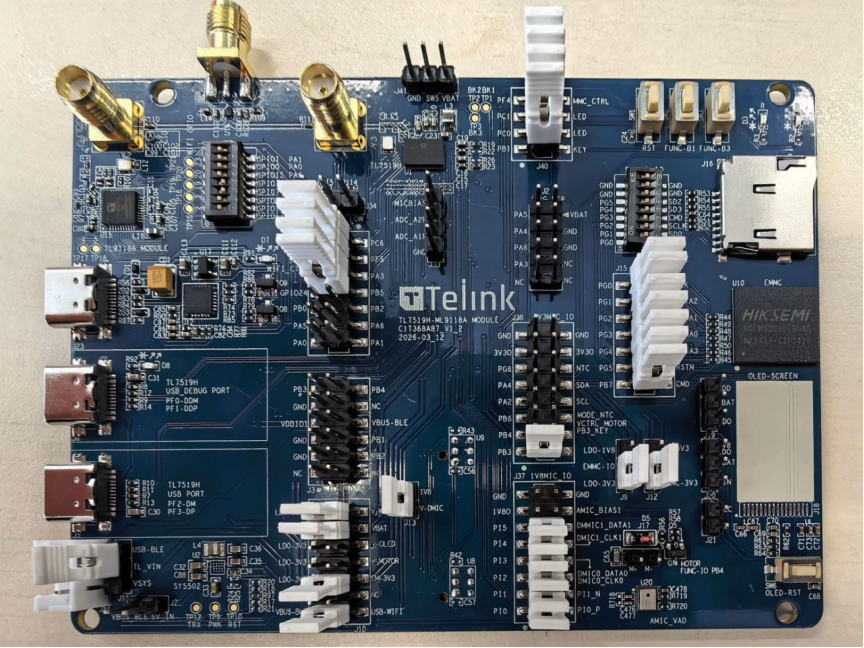
(1) USB Interface
The USB interfaces of the development board are shown below:
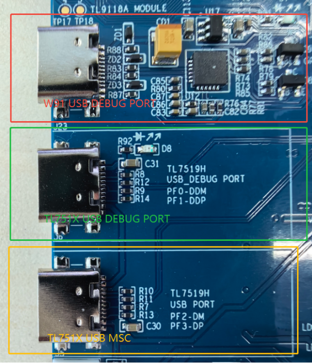
As shown above, from top to bottom, the USB interfaces provide the following functions:
1) The USB interface marked by the red box is connected to the Wi-Fi chip through a USB-to-UART bridge and directly interfaces with TLSR9118. It is used for Wi-Fi firmware download and log output.
2) The green box indicates the USB1 interface of the TL751x, which is used for TL751x USB log output.
3) The yellow box indicates the USB0 interface of the TL751x, which is used for USB Mass Storage Device (U-Disk) functionality and file operations.
-
The button marked by the gray box is the reset button for the TL751x.
-
The button marked by the yellow box is connected to pin PB3 and is defined as Key1 (key1).
-
The button marked by the green box is connected to pin PB1 and is defined as Key2 (key2).
LED Definitions:
-
The LED marked by the blue box is connected to pin PC0 and is defined as LED_BLUE.
-
The LED marked by the red box is connected to pin PC1 and is defined as LED_RED.
-
The usage of the keys and LEDs in the SDK will be described in later sections. This section only provides a basic hardware introduction.
(2) SDIO Interface
The TL751x supports the SDIO interface, and the development board provides two types of storage device interfaces.
- eMMC Device (Default): The development board is equipped with an onboard eMMC storage device. The connection method is shown below: turn off the DIP switch marked by the green box, install all jumper caps in the red box, and connect emmc_3v3 to 3v3 at the gray box. The storage device in the yellow box will then be powered and can communicate with the TL751x.
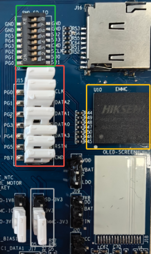
- SD Card: To use an SD card, follow the wiring shown below. Turn on the DIP switch marked by the green box, remove all jumper caps in the red box, and connect SD_3v3 to 3v3 at the gray box. The SD card in the yellow box (inserted separately) will then be powered and can communicate with the TL751x.
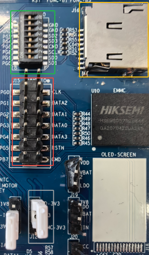
The software configuration will be described in later sections.
(3) Wi-Fi Module Communication Interface and Configuration
To enable Wi-Fi functionality, configure the DIP switches as shown below. Communication between the chips is primarily performed through UART and SPI.
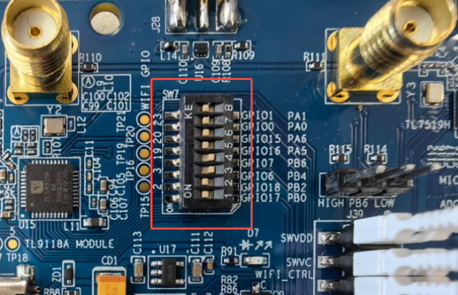
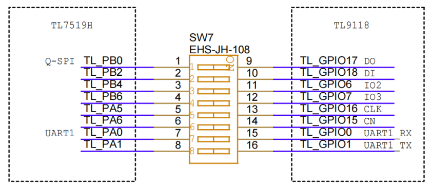
(4) Antenna Hardware
The development board supports two antenna configurations:
-
Independent Antennas (Default): The Bluetooth chip and the Wi-Fi chip each use their own dedicated antenna. Remove the two 0 \(\Omega\) resistors at positions R110 and R111.
-
Shared Antenna: The Bluetooth chip and the Wi-Fi chip share a single antenna using time-division multiplexing. Solder 0 Ω resistors at R110 and R111 to enable the shared antenna configuration.
The locations of R110 and R111 are highlighted by the red box in the figure below.
In the independent antenna configuration, connect whip antennas to the two connectors marked by the yellow boxes. The left connector is for the Wi-Fi antenna, and the right connector is for the Bluetooth antenna. In the shared antenna configuration, only connect a whip antenna to the connector marked by the green box.
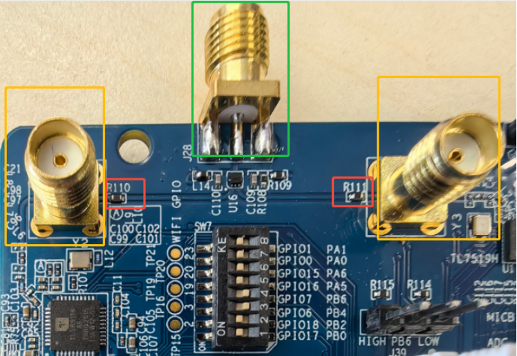
(5) MIC Expansion Board
To use the multi-microphone feature, an external MIC expansion board (C1TXA87_V1_0) is required.
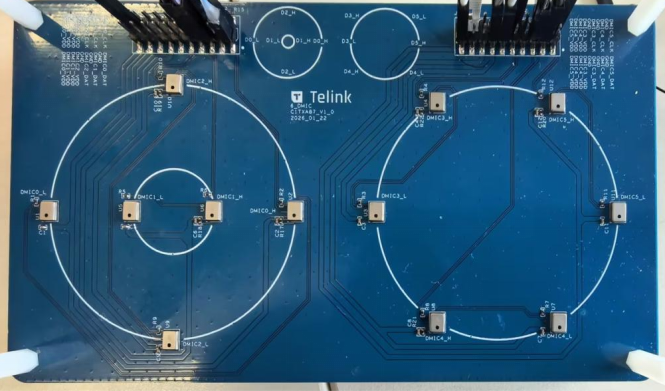
Firmware Compilation and Flashing
(1) Compilation and Flashing Without Boot
TL7519H compilation:
The recording card project uses the bootloader by default. If you are only in the development and validation stage and temporarily cannot use the bootloader to start the project (this may cause RTC and other boot-dependent functions to work abnormally), perform the following steps:
1) Set the TLK_MW_USER_CTRL_ENABLE macro to 0 in app_config
2) Compile the recording_card project
-
The merge_bin.sh script merges and packages the D25F and N22 firmware into:
recording_card_n22_controller_120.bin
-
Program
recording_card_n22_controller_120.bindirectly to address 0x00000000. -
Select the TL751x chip, choose the firmware file, click SWS, then Activate, and finally Download.
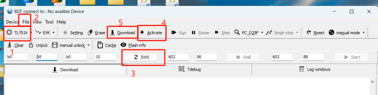
Alternatively, program recording_card.bin to address 0x100000 and controller.bin to address 0x00100000. The merge script essentially combines the two firmware images and fills the gap with 0XFF, reducing two programming operations into one.
TL7519 DSP Firmware Flashing (Important) (Required if DSP functionality is used)
Use the BDT tool, select Tool, choose TWS Tool from the drop-down menu, set the address to 0x00200000, click Browser to select the corresponding DSP binary file, check the option, and click Download.
The DSP firmware is located in thedsp/bin/directory of the SDK. Select the appropriate firmware according to your application. Refer to the Audio Path section for details.
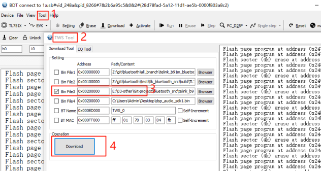
Note
- The DSP supports packaged firmware download. When using the boot startup mode, the shell script automatically packages the DSP firmware. If the non-boot mode is used, the DSP firmware must still be programmed manually at address
0x00200000.
(2) Compilation and Flashing with Boot
If the default bootloader startup method is used, perform the following steps:
1) Make sure the following two macros are enabled by default:
#define TLK_MW_USER_CTRL_ENABLE (1)
#define TLK_MW_OTA_ENABLE (1 && TLK_MW_USER_CTRL_ENABLE)
2) Compile the project to generate the d25f firmware.
3) After the firmware is generated, execute the shell/ota/main_rc_751x_ota.sh script (make sure the file paths in the script are correct). This generates recording_card_ota_firmware.bin in the same directory, which can be used directly for OTA.
4) Program the bootloader firmware to address 0.
5) Program recording_card_ota_firmware.bin to address 0x12000.
Steps 3) through 5) can also be replaced by running main_rc_751x.sh, which packages the bootloader and application firmware into a single image. Simply program the generated firmware to address 0.
If only the Wi-Fi firmware needs to be upgraded, execute the main_recard_ota_wifi script to generate the required Wi-Fi OTA binary file (make sure the file paths are correct).
SDK Features
(1) BLE Features
Users can experience the features through the TelinkRecordCard APP.
Settings:
First, open the Setting page and make sure Auto Request MTU is enabled, and the MTU value is greater than 203. Set Opus Decode Setting to a sampling rate of 16 kHz with a channel count of 1.
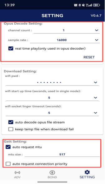
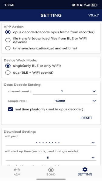
App Actions:
-
Opus Decoder provides a demo: APP controls the device to record audio. The device transmits the recorded audio to the APP over BLE for decoding, and the APP saves the recording as an audio file.
-
File Transfer provides a demo: Users obtain the device file list and download files through BLE or Wi-Fi.
-
Timer sync provides a demo: APP synchronizes the device time over BLE.
Connection Setup:
After power-on, the device starts BLE advertising by default. The default advertising name is Xyris.
Switch to the ADV page in the APP, configure the filter (by device name or MAC address), click Refresh, and select the target device to establish the connection.
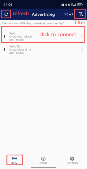
Real-Time Recording (Opus Decoder) Page:
As shown below, users can click Start in the APP to begin recording and Stop to end recording. During recording, the APP plays the audio stream in real time. After recording stops, users can click Save to store the recorded audio.
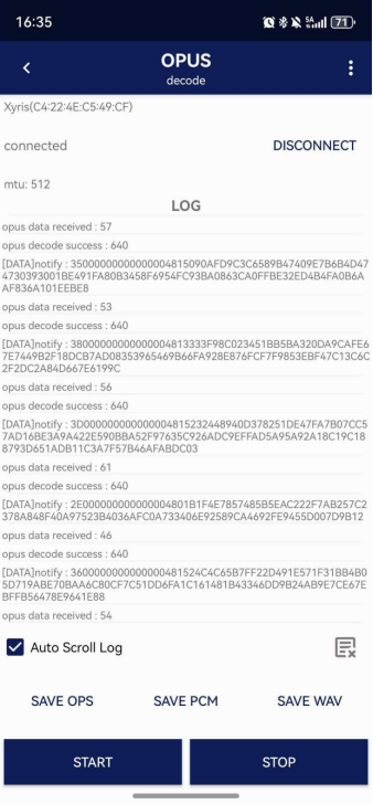
File Download (File Transfer) Page:
As shown below, users can retrieve the file list from the device and perform file renaming, deletion, and download operations.
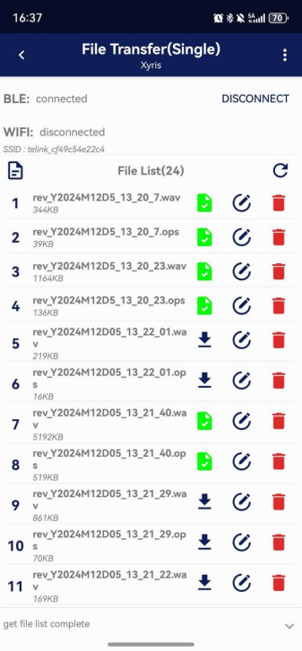
(2) Key Functions
The key functions are defined as follows. The configuration code is located in app_rc_ui_key.c and app_rc_ui_key_plan0.c
| Key Mode | Single Click | Double Click | Triple Click | Quadruple Click | Long Press and Release |
|---|---|---|---|---|---|
| Key1 | Start/Stop Recording | Start/Stop Recording | Enable DSP | Enable WAV File Writing | |
| Key2 | Enable Wi-Fi | Disable Wi-Fi | Disable DSP | Disable WAV File Writing | Enable/Disable USB Mass Storage Mode |
(3) LED Functions
The red LED indicates the recording status, while the blue LED indicates the BLE status. The configuration code is located in app_rc_ui_led.c.
| LED | Off | Solid On | Breathing | Slow Blink |
|---|---|---|---|---|
| Red | Powered Off | Ready (Not Recording) | Recording | / |
| Blue | BLE Disabled | BLE Connected | / | BLE Advertising (Not Connected) |
(4) File System
The SDK provides a set of file read/write interfaces based on FatFs and abstracts diskio to facilitate user customization. The implementation is located in the tlkmw/file directory. Users can configure diskio in tlkmw_fs_diskio.h. Several diskio implementations are provided under tlkmw/file/drc as references. The following example shows the configuration for eMMC.
static sdmmc_pin_config_t sdmmc_emmc_pin_config = {
.sdmmc_clk_pin = GPIO_FC_PG0,
.sdmmc_cmd_pin = GPIO_FC_PB7,
.sdmmc_rst_pin = GPIO_FC_PG5,
.sdmmc_ds_pin = GPIO_NONE_PIN,
.sdmmc_dat0_pin = GPIO_FC_PG3,
.sdmmc_dat1_pin = GPIO_FC_PG2,
.sdmmc_dat2_pin = GPIO_FC_PG1,
.sdmmc_dat3_pin = GPIO_FC_PG4,
.sdmmc_dat4_pin = GPIO_NONE_PIN,
.sdmmc_dat5_pin = GPIO_NONE_PIN,
.sdmmc_dat6_pin = GPIO_NONE_PIN,
.sdmmc_dat7_pin = GPIO_NONE_PIN,
};
SDK encapsulates the eMMC interface driver and defines the global variable tlkmw_fs_diskio_t. The file system can be mounted by providing this global variable to the underlying file system.
const tlkmw_fs_diskio_t gTlkmwFsDiskIoEmmc = {
.init = tlkmw_fs_drv_emmc_init,
.sleep = tlkmw_fs_drv_emmc_sleep,
.awake = tlkmw_fs_drv_emmc_awake,
.write = tlkmw_fs_drv_emmc_write,
.read = tlkmw_fs_drv_emmc_read,
.getSectorSize = tlkmw_fs_drv_emmc_get_sector_size,
.getSectorNum = tlkmw_fs_drv_emmc_get_sector_num,
};
If an SD card is used instead, enable TLK_CFG_FS_SDCARD_DISKIO_ENABLE in app_config and redefine the global variable tlkmw_fs_diskio_t to use the corresponding SD card interface.
(5) U Disk Function
The device supports USB Mass Storage (MSC) functionality. When connected to a computer through the USB1 port, it is enumerated as a USB storage device, allowing users to directly access and manage files on the computer. By default, the USB Mass Storage operates in read-only mode (configurable via the TLK_USB_MSC_READ_ONLY macro). (If read-only mode is disabled, do not format the storage device on the computer. Otherwise, the FAT partition format selected by the host may not match the MCU local file system, resulting in file system corruption.)
The current USB Mass Storage mode uses manual enable/disable control and is disabled by default. Users can enable or disable USB Mass Storage mode through the UI. Mutual exclusion protection is implemented between USB Mass Storage mode and local file operations. When recording or file transfer is in progress, USB Mass Storage mode cannot be enabled. Conversely, when USB Mass Storage mode is enabled, recording and local file operation requests will be rejected.
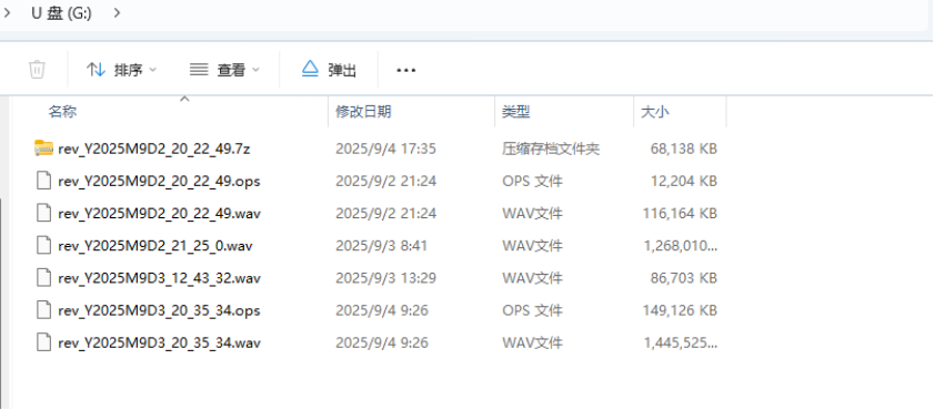
(6) OTA Function
OTA can be verified using the TelinkBootOTA app.
Usage procedure: Copy recard_ota_firmware.bin to a folder on the mobile phone, connect the app, select the firmware to be upgraded, and click Start.
(7) Audio Path and Multi-Microphone BBF Function
Audio Path Overview:
External sound is captured by a microphone or microphone array and converted into digital audio with a sampling rate of 16 kHz and a bit depth of 16 bits. The captured signal is first enhanced by Blind Beamforming (BBF) to improve the target speech signal (BBF is not supported in the single-microphone configuration). The enhanced signal is then processed by Neural Network Noise Suppression (NN_NS) to reduce environmental noise. After that, Automatic Gain Control (AGC) automatically adjusts the audio level. Finally, the audio is encoded using OPUS for local storage or RF transmission. In addition, the data of the entire audio processing chain can be extracted through the SPI interface for analysis.
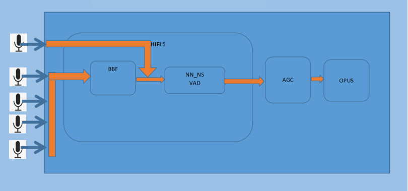
A brief description of the audio path is as follows:
- BBF (Blind Beamforming) is a beamforming technique that enhances the target speech signal and suppresses noise by using information collected from a microphone array, even when the signal model and source signal are not precisely known. Its primary function is to combine data from multiple channels, suppress noise and interference from undesired directions, and enhance signals arriving from the target direction.
The TL751x recording card solution supports 2-MIC, 4-MIC, and 6-MIC BBF algorithms, all implemented on the DSP. The following figure illustrates the principle of blind beamforming.
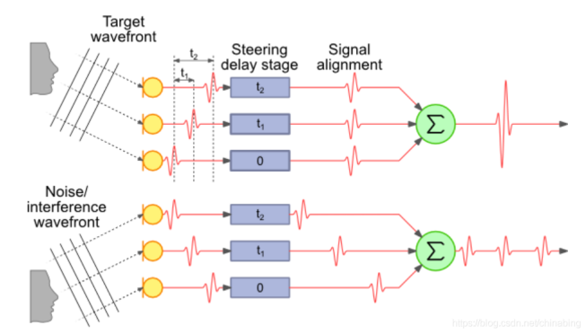
-
NN_NS (NN-based Noise Suppression) is a neural network-based noise suppression algorithm. It learns the nonlinear relationship between speech and noise through supervised training, enabling more accurate estimation of speech characteristics while suppressing background noise and preserving the naturalness and clarity of speech. In the TL751x recording card solution, the NN_NS algorithm is implemented on the DSP.
-
VAD (Voice Activity Detection) is a speech endpoint detection technology. Its primary function is to accurately detect the start and end points of speech in noisy environments, effectively separating silence from actual speech. During silent periods, it helps save valuable computing resources, storage space, and transmission bandwidth.
-
AGC (Automatic Gain Control) automatically adjusts the audio gain to maintain a consistent output volume, preventing speech from becoming too loud or too quiet due to changes in the distance between the speaker and the microphone. This algorithm is implemented on the D25F processor. The following figure shows the AGC effect.
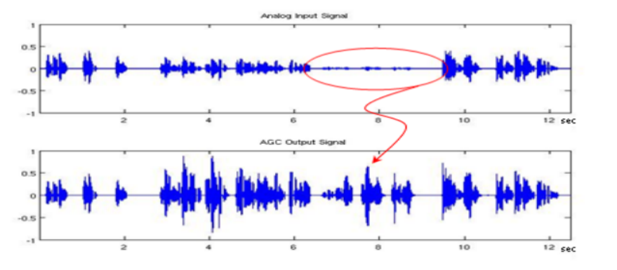
Single-Microphone / Multi-Microphone Solutions:
The EVB hardware uses the single-microphone recording solution by default. To use the multi-microphone solution, several hardware settings must be confirmed.
Hardware Configuration for the Single MIC:
In the single-microphone solution, the default microphone mounted on the EVK board is used. Before use, verify the following hardware configuration:
| Name | Pin 0 | Pin 1 | Status |
|---|---|---|---|
| Power | J13_1 |
J13_2 |
Shorted |
DMIC1_CLK1 |
J37_9 |
J37_10 |
Shorted |
DMIC1_DATA1 |
J37_11 |
J37_12 |
Shorted |
As shown in the following figure:
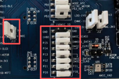
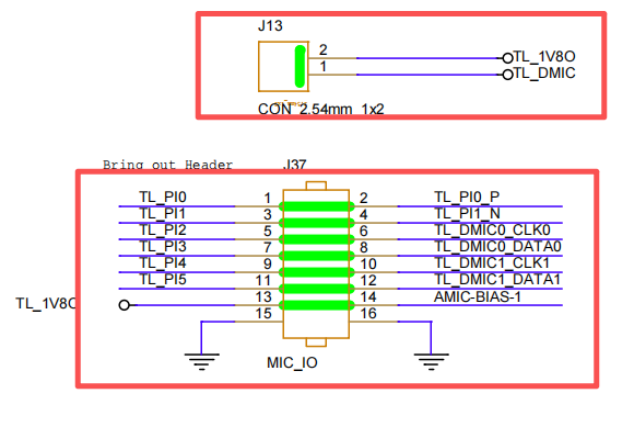
Multi-MIC Hardware Configuration:
For the multi-MIC solution, an external MIC expansion board is required. Corresponding hardware settings must also be made on the recording card mainboard. Configure the recording card EVK as shown in the table below:
| Name | Pin 0 | Pin 1 | Status |
|---|---|---|---|
| Power | J13_1 |
J13_2 |
Disconnected |
DMIC0_CLK0 |
J37_5 |
J37_6 |
Disconnected |
DMIC0_DATA0 |
J37_7 |
J37_8 |
Disconnected |
DMIC1_CLK1 |
J37_9 |
J37_10 |
Disconnected |
DMIC1_DATA1 |
J37_11 |
J37_12 |
Disconnected |
TL_PB4 |
J38_3 |
J38_4 |
Disconnected |
TL_PB6 |
J38_5 |
J38_6 |
Disconnected |
The wiring between the recording card mainboard and the MIC expansion board is shown below.
2MIC BBF Recording Card Mainboard and Multi-MIC Expansion Board Wiring:
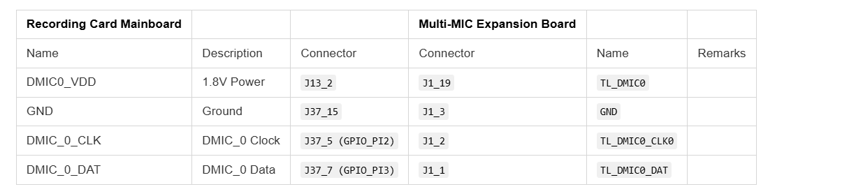
4MIC BBF Recording Card Mainboard and Multi-MIC Expansion Board Wiring:
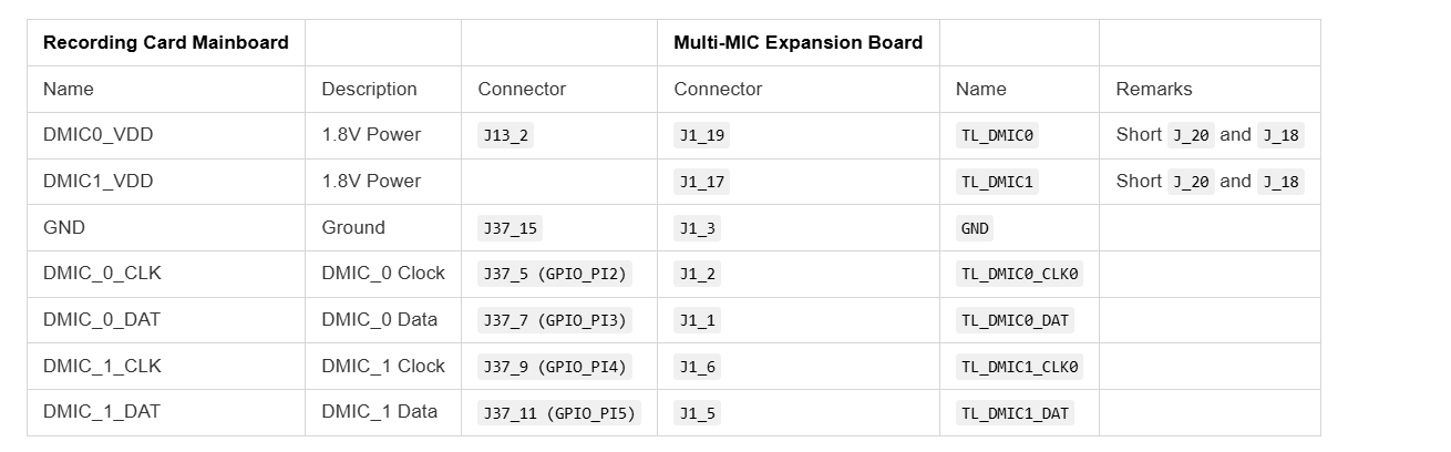
6MIC BBF Recording Card Mainboard and Multi-MIC Expansion Board Wiring:
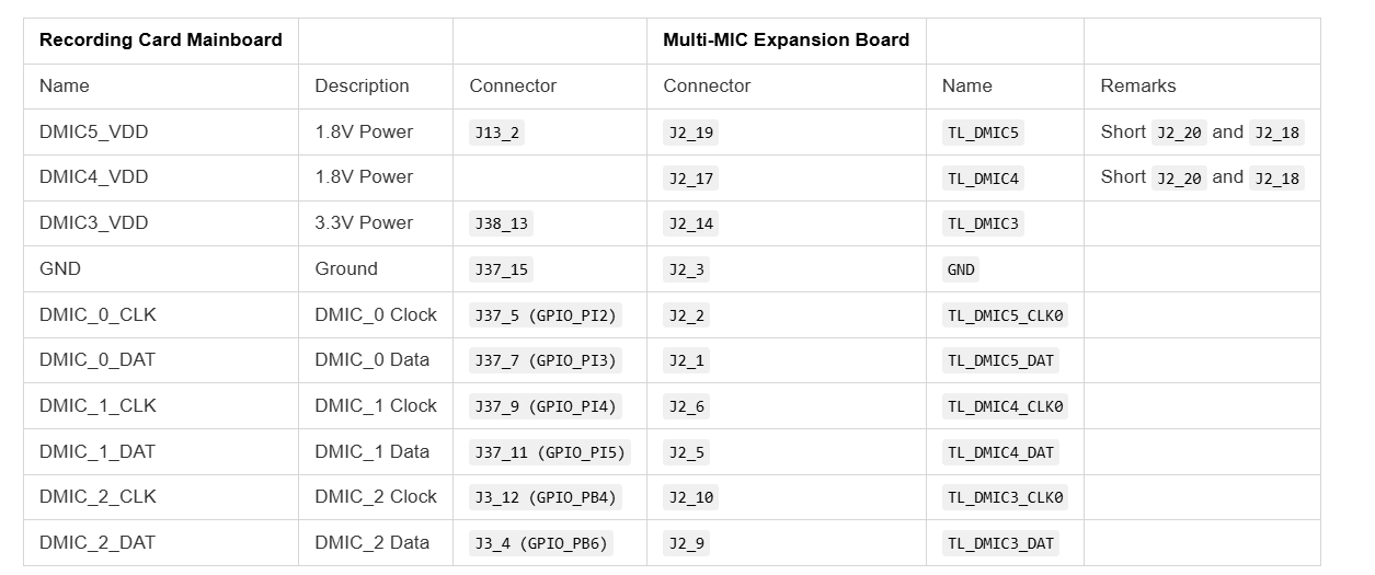
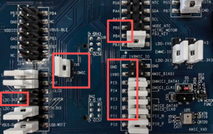
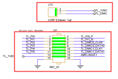
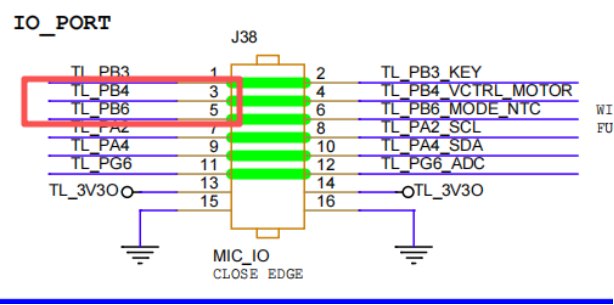
Software Configuration:
Single-MIC or multi-MIC recording can be configured through the following macro definitions and settings. The example below shows the configuration for 6-MIC recording. Note:The hardware configuration and software configuration must match exactly.
///disable and CHN for BBF
#define TLKALG_BBF_DIS 0
#define TLKALG_BBF_2CH_EN 2
#define TLKALG_BBF_4CH_EN 4
#define TLKALG_BBF_6CH_EN 6
///BBF
#define TLKALG_BBF_ENABLE TLKALG_BBF_6CH_EN ///config dis or CHN
Functional Usage:
After power-on (a complete power cycle is recommended to ensure proper initialization), according to the UI key mapping, triple-click KEY0 to test either single-MIC recording (with the NN-NS algorithm) or multi-MIC recording (with the BBF and NN-NS algorithms). Triple-click KEY1 to disable the corresponding BBF and NN-NS algorithm functions.
(8) Wi-Fi Fast File Transfer
Please contact your FAE for the Wi-Fi firmware and SDK.
The SDK supports two modes: shared antenna mode and independent antenna mode:
- In independent antenna mode, BLE and Wi-Fi connections can coexist. The mobile APP uses the BLE link to notify the device which file to download, and then receives the file data over the Wi-Fi link. After the Wi-Fi connection is established, tapping Download in the APP UI transfers the file via the Wi-Fi link.
- In shared antenna mode, only one of the BLE or Wi-Fi connections can remain active at a time. The original BLE command channel is transparently forwarded through the Wi-Fi link. The APP provides a switch button that allows users to switch to the Wi-Fi link for fast file transfer.
(9) BT Headset Audio Path
This feature is customized for specific customers. If you do not require this functionality, please ignore this section.
This SDK provides a demo for connecting to a BT headset. Coexistence between Classic Bluetooth and Bluetooth Low Energy timing is currently not supported. Please ensure that only one over-the-air link is active during operation (i.e., the conventional recording mode and BT mode cannot coexist); otherwise, unexpected behavior may occur. The BT link is used as follows:
-
Configure
TLK_RC_CFG_BT_CENTRAL_STREAMto 1 inapp_config.hto enable the BT Central role, then compile and burn the firmware. -
Use the USB shell to establish a connection with the BT headset (see
tlkusb_debug_shell_hookfor the implementation):a. Enter
11 01 00 00to disable BT SCAN. (This reduces bandwidth allocation and speeds up device discovery.)b. Put the BT headset into pairing mode, then enter
11 02 04on the device to start BT INQUIRY for headset discovery.c. After the target headset appears in the log, enter
11 03to stop BT INQUIRY.d. Enter
11 04to print the list of discovered devices.e. Enter
11 05 XXto connect to the desired device in the discovered device list, where XX is the device index (refer to the list printed in Step d).


As shown in the example, entering 11 05 02 connects to AirPods Pro (device index 2).
If the headset has already been paired with the development board, Steps a–e are unnecessary. Simply enable SCAN (automatically enabled for 120 seconds after power-on or enabled manually), open the headset charging case, and wait for the headset to initiate automatic reconnection.
- Use the USB shell to trigger the A2DP/SCO demo (see
tlkusb_debug_shell_hookfor the implementation):
Enter 11 07 to start the A2DP music demo, and enter 11 08 to stop it. In A2DP mode, the headset receives a sine-wave audio stream transmitted by the recording card. Users can modify the tlkmdi_a2dp_out_read_samples function to replace the sine-wave source with their own audio stream processing logic.
Enter 11 09 to start the SCO voice demo, and enter 11 0a to stop it. In SCO voice mode, the device mixes the audio received from the headset microphone with a sine-wave signal and loops the mixed audio back to the headset for playback. Users can customize the mixing logic and its invocation point in the tlkmdi_record_fill_spk_data_to_uac function according to product requirements.
(10) BT Mobile Phone Audio Path
This feature is customized for specific customers. If you do not require this functionality, please ignore this section.
This SDK provides a demo for connecting to a BT mobile phone. Coexistence between Classic Bluetooth and Bluetooth Low Energy timing under high-bandwidth scenarios is currently not supported and may cause unexpected behavior. The BT mobile phone link is used as follows:
-
Configure
TLK_RC_CFG_BT_PERIPHERAL_STREAMto 1 inapp_config.hto enable the BT Peripheral role, then compile and burn the firmware. -
Within 120 seconds after power-on, the chip automatically enables page scan/inquiry scan. The mobile phone can discover and connect to the device via the Bluetooth settings interface, establishing both the ACL link and the HFP profile connection.
-
When there is an incoming or active call on the mobile phone, an SCO connection is established with the device. The device Speaker plays the audio from the remote side, while the MIC captures audio and transmits it to the remote device. The PCM data played by the Speaker can be obtained through the
bt_audio_get_spk_data_cbcallback, and the MIC data can be obtained through thebt_audio_get_mic_data_cbcallback.
Note
- Since the recording card development board does not expose a Speaker interface, this demo has been adapted for the standard TL751x EVK: C1T368A20. Enabling
TLK_RC_CFG_BT_PERIPHERAL_STREAMautomatically selects this development board. (Please ignore all wiring instructions described in the previous sections.)
Code Architecture
(1) Code Architecture
As shown in the figure below, the project directory consists of the app_recording_card directory, the ble directory, and several other files.
The app_recording_card directory contains the logic code for the recording card, while the ble directory contains all BLE-related logic. These two modules are architecturally separated and run as two independent threads.
The project macros are configured in app_config.h, and main.c contains the main function and MCU platform configuration.
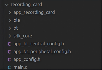
app_recording_card Directory:
The structure of the app_recording_card directory is shown below:
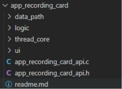
As shown in the figure, the app_recording_card directory contains the data_path, logic, thread_core, ui, and API directories/files.
-
The
readme.mdfile describes some terminology and the UI logic. -
The
app_recording_card_apiprovides related APIs for the key UI and BLE CMD. -
The
data_pathdirectory abstracts various data paths, including the recording input stream (stream in), BLE upload stream (stream out), Wi-Fi upload stream (stream out), and file read stream. in indicates that the input stream is writable, while out indicates that the output stream is readable. -
The
logicdirectory mainly contains the application logic, including recording start/stop and data stream transmission. -
The
thread_coredirectory contains the core code of the thread, including thread definitions and asynchronous message processing logic. -
The
uidirectory contains UI logic such as key handling and OLED (currently not enabled).
BLE Directory:
The structure of the BLE directory is shown below:
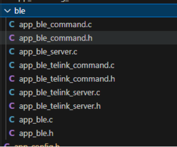
app_ble.cconfigures BLE advertising data, including the device name, SN, and other information.app_ble_telink_server.cmainly handles commands and responses for communication with the Telink Opus Decode APP.app_ble_telink_command.cprocesses commands from the Telink APP, such as querying the Opus file list, reading file information, deleting files, and so on.app_ble_server.cmainly handles commands and responses for communication with the Xyris APP.app_ble_command.cprocesses commands from the Xyris APP and currently implements the commands supported by the APP.
BT Directory:
app_bt.c is responsible for registering BT-related callback functions and configuring startup hooks.
(2) Design Concept
The project adopts a multithreaded concurrent architecture. Different threads communicate asynchronously through a message/event mechanism, reducing coupling while ensuring thread safety. The overall software architecture is shown in the following figure.
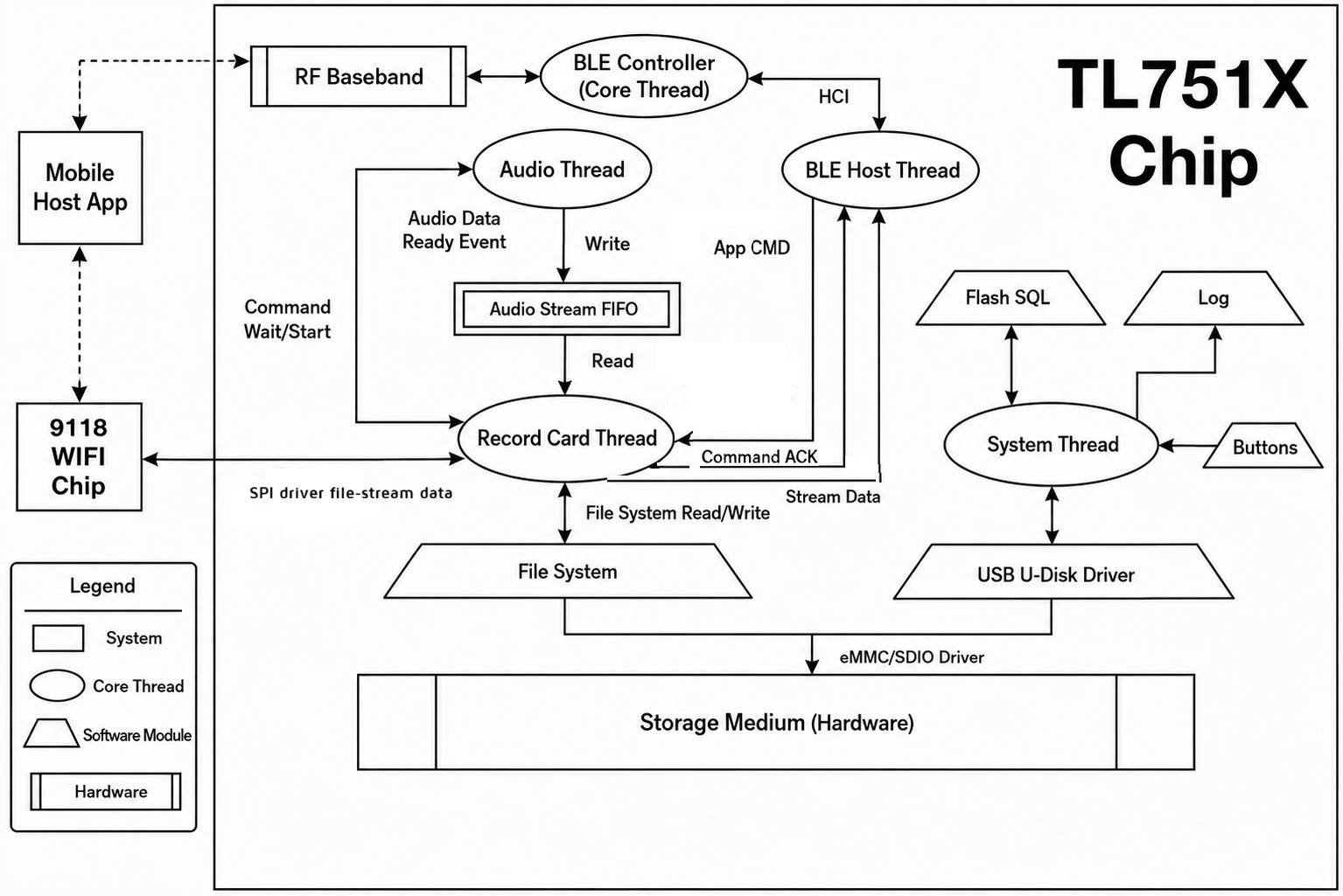
-
The
audiothread is responsible for recording, audio noise suppression, and data encoding. It asynchronously receives recording start/stop commands from the recording card thread. When the system is not recording, this thread remains blocked. During recording, it periodically encodes the recorded audio, pushes the encoded data into a shared FIFO, and wakes up the recording card thread to distribute the data (saving it to the file system or uploading it to the mobile APP via BLE). -
The
systhread is mainly responsible for log output, key handling, SQL storage, and USB-related modules. -
The
ble controllerthread/core is responsible for BLE link management and packet transmission/reception at the lower layer. At the software level, it communicates only with theble hostthread. -
The
ble hostthread is responsible for application-level data exchange with the mobile APP. It decodes commands from the APP, repackages them as CMD messages, and sends them to the recording card thread through a message queue for processing. After the recording card thread finishes processing the command asynchronously, it sends a CMD ACK back to theble hostthread, which repackages the response and forwards it to the mobile APP. This thread also receives real-time recording data distributed by the recording card thread and reports it to the mobile APP. -
The recording card thread mainly performs the following tasks:
- Receives commands from the BLE host thread, such as starting recording, reporting the Opus file list, and deleting files, processes them asynchronously, and returns a CMD ACK.
- Receives key UI events from the sys thread to control recording start and stop.
- Wakes up the audio thread to start real-time recording, reads data from the audio stream FIFO, and distributes the data (saving it to the file system or uploading it via BLE in real time).
- Uploads recorded files through either the BLE or Wi-Fi path (forwarded through SPI).
tlkapp.c contains the thread creation logic:
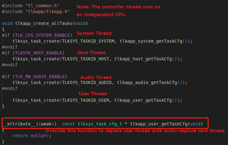
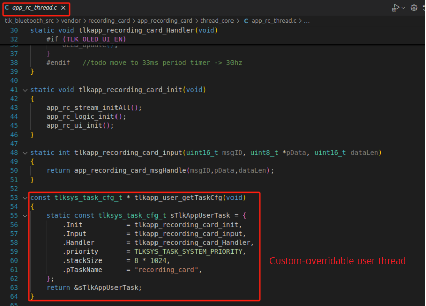
(3) Overview of the Message Passing Mechanism
To ensure thread safety, avoid various critical-section bugs, and reduce code coupling, the ble host thread does not directly execute the recording card business logic after receiving commands from the APP. Instead, it encapsulates the commands into messages and sends them to the recording card thread asynchronously through a message queue (mailbox). After processing is completed, the recording card thread returns the corresponding CMD ACK. To improve code decoupling, facilitate low-power integration, and simplify code merging into the SDK for secondary development, users are strongly recommended to follow this design pattern in their own development.
All API functions called from outside the thread send messages.
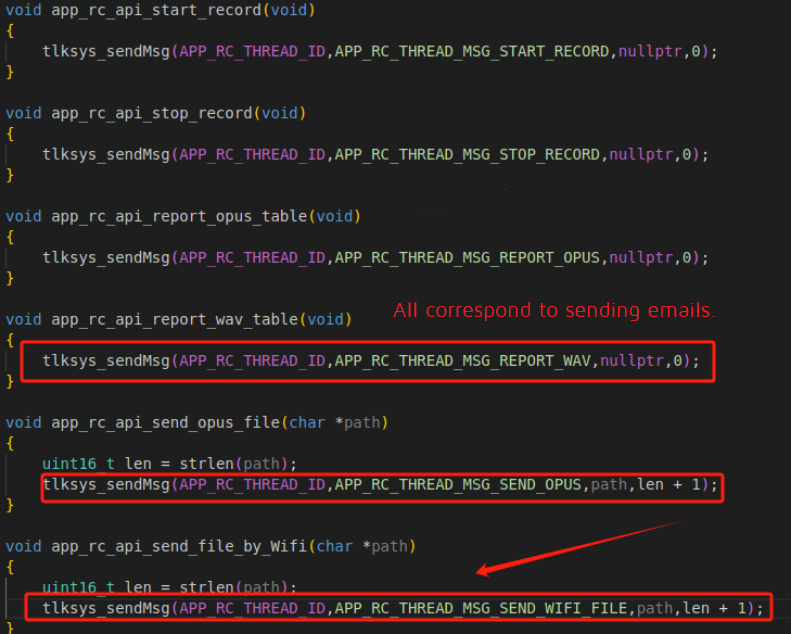
After receiving a message, the thread executes the corresponding application logic.
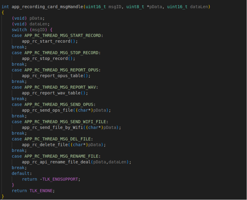
BT Interphone
Overview
This chapter introduces the BT Interphone reference design in the Bluetooth Audio SDK. BT Interphone is an audio application designed for Bluetooth intercoms and Bluetooth helmet headsets. Based on the Telink SDK, it provides Classic Bluetooth audio, Mesh intercom, and dual-connection management. It supports simultaneous connections to a mobile phone (A2DP/HFP) and a headset, enabling music playback, phone calls, and intercom communication between devices.
The main features are as follows:
-
Classic Bluetooth Features:
- Supports BT pairing, reconnection, role switching, and other link management functions
- Supports Secure Simple Pairing (SSP) and Adaptive Frequency Hopping (AFH)
- Supports dual Classic Bluetooth connections (two mobile phones simultaneously, or one mobile phone and one headset)
- Supports A2DP SNK music playback (SBC/AAC decoding)
- Supports HFP HF/AG call functionality
- Supports AVRCP media control
- Supports SPP data transmission
- Supports SPP data transmission
-
LE Features:
- Supports BLE ACL Peripheral connection
-
Interphone Features:
- Supports Mesh network intercom (requires the TL721x platform)
- Supports the I2S audio data path
- Supports DSP audio processing (such as NN noise suppression)
- Supports switching among Music, Call, and Mesh audio modes
- Supports the Sidetone feature
Directory Structure
bt_interphone
├── app_acl_peripheral.c // BLE ACL Peripheral initialization and connection management
├── app_audio.c // Audio task creation and PCM data callback registration
├── app_ble.c // BLE stack initialization and HID/Headset registration
├── app_ble_headset.c // BLE Unicast Server Headset initialization
├── app_ble_hid.c // BLE HID volume control
├── app_bt.c // BT ACL/Profile connection, disconnection, and reconnection handling
├── app_config.h // Project configuration file
├── app_config_ex.h // Extended configuration file
├── app_emi_bqb.c // EMI/BQB test functions
├── app_key_led_config.c // Key configuration file
├── app_product_test.c // Production test functions
├── app_usb_shell.c // USB debugging shell command processing
└── main.c // Project entry
BT Host
The BT Host implementation of BT Interphone is based on the complete BT Host interface described in the btble headset chapter, covering key events such as ACL and Profile connection/disconnection. On top of this, BT Interphone adds the following features:
- Register ACL connection, encryption, and disconnection callbacks:
static void app_btmgr_aclConnectCB(uint16_t handle, uint8_t status, uint8_t *pBtAddr, uint8_t dtype, uint8_t hfp_ChId)
This function is the application-layer callback invoked when an ACL connection is established. BT Interphone supports simultaneous connections to two different types of devices (such as a mobile phone and a headset), and dynamically adjusts the scan strategy according to the connected device type.
static void app_btmgr_aclEncryptCB(uint16_t handle, uint8_t status, uint8_t *pBtAddr, uint8_t dtype, uint8_t hfp_ChId)
This function is the callback invoked when link encryption is completed. After encryption, it initiates SDP service discovery and appends the corresponding Profiles based on the device type.
static void app_btmgr_aclDisconnCB(uint16_t handle, uint8_t reason, uint8_t *pBtAddr, uint8_t dtype)
This function is the callback invoked when an ACL connection is disconnected. Upon disconnection, it releases the audio scheduler resources and triggers reconnection if the ACL link is lost due to a timeout.
- Dynamically append Profiles based on the device type:
static void app_btmgr_appendProfile(uint16_t aclHandle)
This function dynamically appends A2DP, HFP, AVRCP, HID, and other Profiles according to the connected device type (mobile phone, PC, or headset). For mobile phones and PCs, it appends the A2DP SNK and HID Server Profiles. For previously paired devices, it appends HFP and other Profiles based on the stored RFC Channel information.
- Remote device name filtering:
#if (TLK_CHECK_REMOTE_DEV)
void tlkmdi_btacl_getRemoteNameChange(uint8_t *pData)
This feature filters remote devices based on their Bluetooth names and modifies the device type for specified names (such as "X5 9TWMCC"). It can be used, for example, to identify sports cameras.
- Power-on reconnection and scan control:
void tlkapp_host_bt_taskStartHook(void)
This function is called when the BT Host task starts. If the last paired device was a mobile phone or a similar device, it initiates reconnection. If the last paired device was a headset or a similar device, it enters Page Scan mode and waits for an incoming connection.
LE Host
The LE Host of BT Interphone includes the following functional modules:
- BLE ACL Peripheral:
void app_ble_acl_peripheral_init(void);
void app_ble_acl_peripheral_start(void);
Initializes the BLE ACL Peripheral function, configures the advertising parameters, starts advertising, and supports BLE device connection and pairing.
BLE stack initialization is implemented in app_ble.c :
void tlkapp_host_le_init(void)
This function initializes the BLE stack, sets the MAC address, and registers the ACL Peripheral, HID, and other services.
Interphone Module
The Interphone module is located in the tlkmw/audio/interphone/ directory and is the core functional module of BT Interphone.
(1) Module Initialization
int tlkmdi_interphone_init(void);
This function initializes the Interphone module, including:
- Initializing the Link Manager (Bluetooth music link management)
- Initializing the Mesh Manager (Mesh intercom management)
- Initializing the HF Manager (call management)
- Initializing the audio buffer
- Initializing the I2S interface
- Initializing the audio algorithms
(2) Audio Mode Control
Interphone supports three audio modes:
- MESH Mode: Mesh network intercom
void tlkmdi_interphone_mesh_control(uint8_t isStart);
Starts/stops the Mesh intercom function and controls the enable state of the I2S TX/RX DMA.
- MUSIC Mode: Bluetooth music playback
void tlkmdi_interphone_bt_music_control(uint16_t handle, uint8_t isStart);
Starts/stops Bluetooth music playback and supports SBC and AAC decoding.
- AG Mode: Call mode
void tlkmdi_interphone_voice_control(uint16_t acl_handle, uint8_t is_start, uint8_t codec);
Starts/stops the call function and supports CVSD and mSBC encoding/decoding.
(3) Operation Interface
bool tlkmdi_interphone_operate(uint16_t handle, uint8_t opcode, uint8_t *pdata, uint16_t dataLen);
This function provides the operation interface for Interphone and supports the following operation codes:
TLKAUD_OPCODE_VOLUME_INC: Increase volumeTLKAUD_OPCODE_VOLUME_DEC: Decrease volumeTLKAUD_OPCODE_TRIGGER_CUSTOMIZED_PLAYPAUSE: Toggle Play/Pause
Key Functions
| KEY | Single Click | Double Click | Triple Click | Long Press |
|---|---|---|---|---|
| KEY1 | Play/Pause Music | Next Track | Enter Pairing Mode | |
| KEY2 | Answer the Most Recent Incoming Call | Previous Track | ||
| KEY3 | Volume+ | Volume- | Trigger Siri | |
| KEY4 | End Call |
Configuration Files
(1) Key Configurations in app_config.h
#define TLK_BT_MULTIPNT_ENABLE (1) // Enable dual connections
#define TLK_STK_BTACL_NUMB 2 // Number of ACL connections
#define TLK_STK_BTSCO_NUMB 2 // Number of SCO connections
#define TLK_INTERPHONE_ENABLE 1 // Enable Interphone
#define TLK_CHECK_REMOTE_DEV 1 // Enable remote device name filtering
#define TLK_APP_REMOTE_NAME_DATA "X5 9TWMCC" // Target device name for filtering
// BT Profile Configuration
#define TLK_STK_BT_ENABLE 1
#define TLKBTP_CFG_A2DP_ENABLE 1
#define TLKBTP_CFG_A2DPSNK_ENABLE 1
#define TLKBTP_CFG_HFP_ENABLE 1
#define TLKBTP_CFG_HFPHF_ENABLE 1
#define TLKBTP_CFG_HFPAG_ENABLE 1
#define TLKBTP_CFG_AVRCP_ENABLE 1
#define TLKBTP_CFG_SPP_ENABLE 1
// LE Audio Configuration
#define TLK_STK_BLE_ENABLE 1
#define TLK_MW_LEA_US_MUSIC_ENABLE 1
#define TLK_MW_LEA_US_VOICE_ENABLE 1
// Interphone I2S Configuration
#define TLKMW_INTERPHONE_EN 1
#define TLKMW_FIFO_IRQ_EN 1
#define TX_FIFO_IRQ_ENABLE 1
#define INTERPHONE_I2S_FIFO FIFO3
#define TLK_PCM_DATA_WR_EN 1
(2) Extended Configurations in app_config_ex.h
#define TLK_CFG_BT_EX_PAIRING_MODE_ENABLE 1 // Enable extended pairing mode
Audio Task Creation
Create the Interphone audio task in app_audio.c :
void app_audio_create_interphone_task(void)
{
tlkapp_audioScheduler_taskInfo_t info = {
.audioType = TLKAPP_AUDIO_SCHEDULER_AUDIO_TYPE_MUSIC,
.optype = TLKAUD_TYPE_INTRTPHONE,
.priority = tlkapp_audioScheduler_getDefaultPriority(TLKAUD_TYPE_INTRTPHONE),
.state = TLKAPP_AUDIO_SCHEDULER_TASK_STATE_IDLE,
};
uint32_t taskID = 0XFFFF + ((uint32_t)TLKAUD_TYPE_INTRTPHONE << 16);
tlkapp_audioScheduler_updateTask(taskID, info, 0);
}
Audio Path Verification
(1) Bluetooth Audio Verification
Single Bluetooth Connection Verification:
- Mobile Phone Music and Call Verification
Connect a mobile phone and verify that both music playback and phone calls work correctly, ensuring normal uplink and downlink audio.
- Headset Call Verification
Connect a Bluetooth headset (or another development board), then send the USB command 11 01 09 to start a call. Verify that audio can be heard on both sides.
Dual Bluetooth Connection Verification:
- Music Preemption Verification
Connect two mobile phones. Phone A starts playing music first, then Phone B starts playing music. The music from Phone B preempts Phone A. After music playback on Phone B is paused, playback automatically resumes on Phone A.
- Call Non-Preemption Verification
Phone A initiates a call first, followed by Phone B. The call from Phone B does not preempt the call from Phone A. After the call on Phone A ends, the system automatically switches to the call on Phone B.
- Call Preempts Music Verification
Phone A starts playing music, then Phone B initiates a call. The incoming call preempts music playback, giving priority to call audio.
(2) Mesh Audio Verification
By shorting the I2S ADC and DAC pins (PI3 and PI4), you can hear your own voice. The audio path is: MIC -> NN -> I2S OUT = I2S IN -> SPK.
Use the following USB commands to join or leave a Mesh network:
| Function | USB Command |
|---|---|
| Join Mesh Network | 11 10 24 |
| Leave Mesh Network | 11 10 25 |
(3) Sidetone Verification
Use the following USB commands to enable or disable the Sidetone function. When enabled, you can hear your own voice:
| Function | USB Command |
|---|---|
| Enable Sidetone | 11 10 20 |
| Disable Sidetone | 11 10 21 |
(4) Prompt Tone Verification
Program the tone files into Flash at the addresses specified in the Tone Download section. Prompt tones can then be heard during events such as Bluetooth connection and disconnection.