BLE/Zigbee/Thread Radio Co-Processor Getting Started
Overview
This document is intended to help you quickly complete firmware flashing and functional verification of the BLE/Zigbee/Thread (BZT) Radio Co-Processor (RCP) example. With this document, you will become familiar with the configuration of the BZT concurrent RCP, and use it to control devices based on three different protocols: Bluetooth Low Energy (BLE), Zigbee, and Matter over Thread.
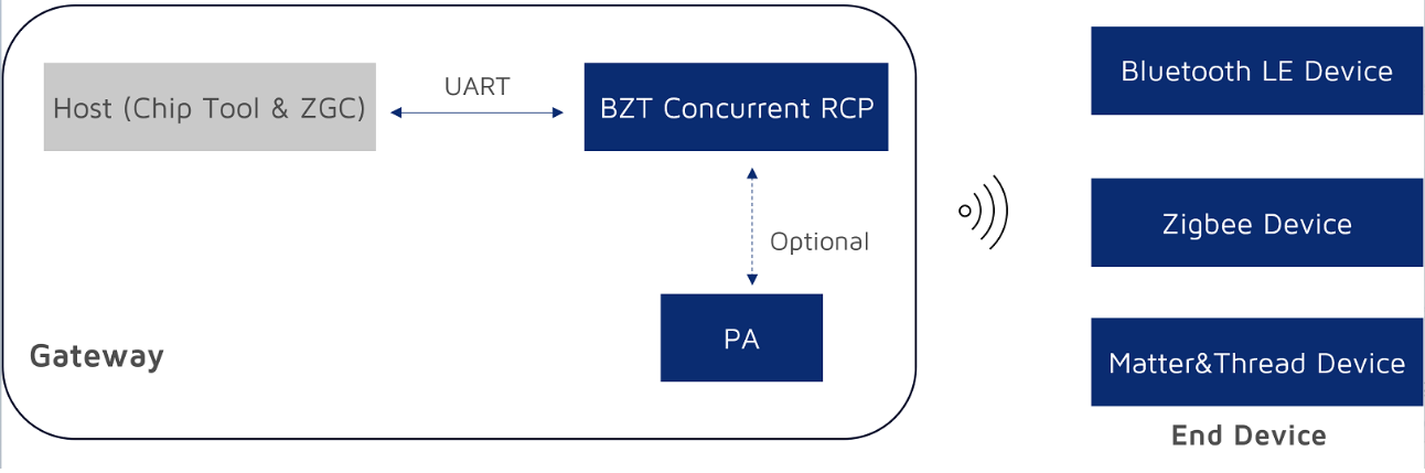
Hardware and software preparation
Hardware checklist
| Hardware type | Model/specification | Quantity | Description |
|---|---|---|---|
| PC | Linux computer with Ubuntu 24.04 LTS | 1 | Serves as the development host. |
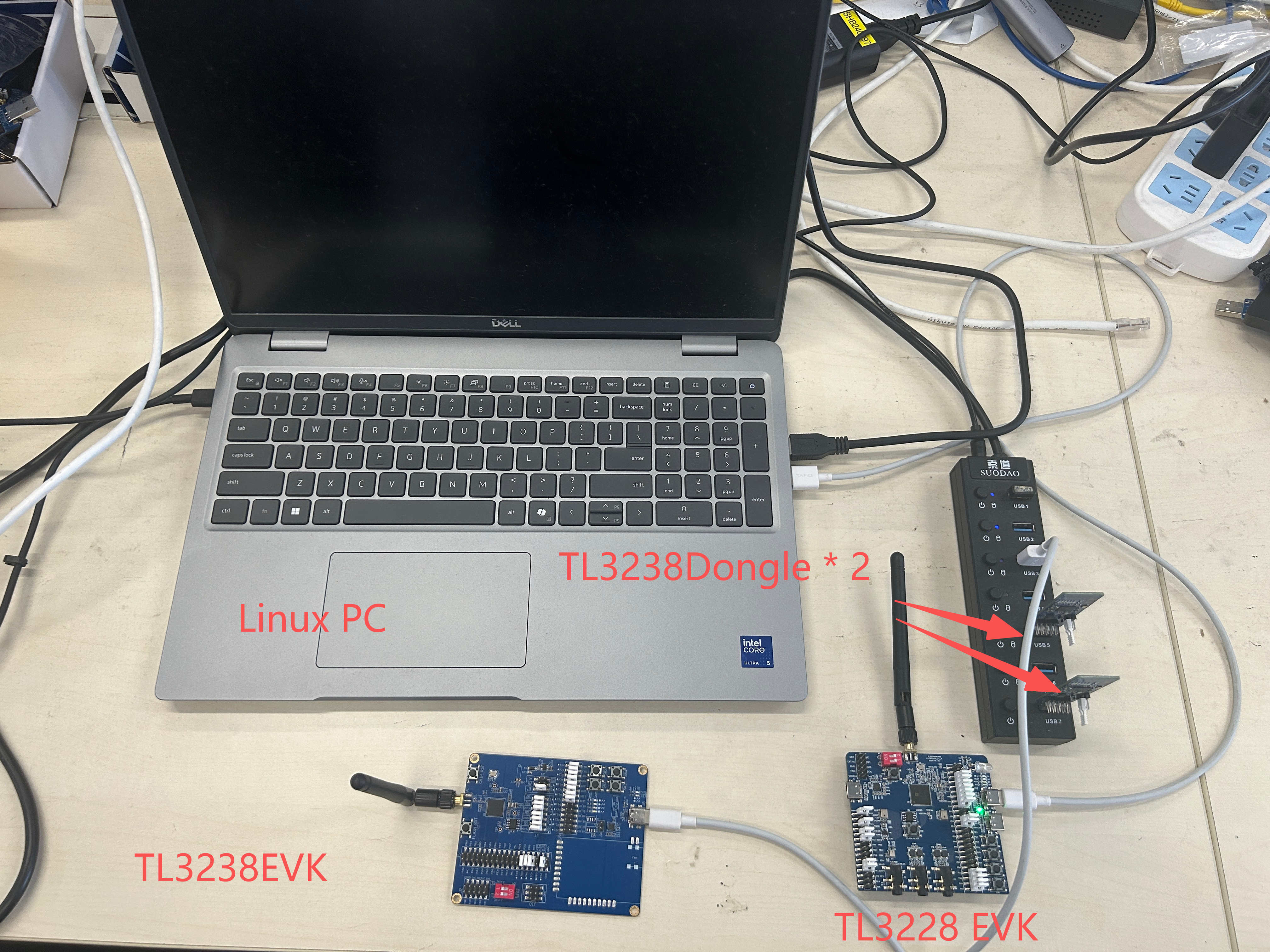
| Development board | TL322x development board | 1 | TL3228x development board, used to flash the RCP firmware. |
| TL323x development board | 1 | TL3238x development board, used as the Matter device network test node. | |
| TL3238 Dongle | 2 | One as the Zigbee device network test node; one as the BLE device network test node. | |
| Telink programmer | Programmer V5 | 1 | Used to flash firmware to the development boards. |
| Cable | USB Type-C cable | Several | Connects the PC to the programmer, providing the flashing channel. Connects the PC to the development board for power supply and log output. |
| Dupont wires | Several | Connect the programmer to the debugging/flashing interface of the development boards. |
The development boards can be purchased from DigiKey. The programmers will be available at a later date. Any questions, please feel free to contact us.
Note
Make sure that the antenna is installed on all development boards before use to ensure proper wireless communication.
Software and firmware checklist
| Software type | Name | Description |
|---|---|---|
| Flashing tool | Telink BDT for Linux | Dedicated flashing and debugging software for programming firmware to the development boards. |
| Precompiled firmware | ot-zb-ble-rcp_322x_usb.bin |
RCP firmware, flashed to the TL3228x development board, with the OpenThread/Zigbee/BLE protocol stacks integrated. |
sampleLight_tl323x.bin |
Zigbee light control firmware, flashed to the TL3238 Dongle. | |
zigbee_ble_sampleGW_tl323x.bin |
BLE firmware, flashed to the TL3238 Dongle. | |
merged_lighting_tl323x_fd_1fd000.bin |
Matter application firmware, flashed to the TL3238x development board. It must be used together with the factory data in the factory_data_1141_8005_0x1fd000/1141_8005 directory.The application firmware is flashed starting at address 0x0, and the factory data is flashed starting at address 0x1fd000. |
|
| Factory data | factory_data_1141_8005_0x1fd000 |
Flashed together with the Matter application firmware (provided along with the precompiled firmware). |
Note
Click Download to get the precompiled firmware, factory data, and the Linux package of the ZGC tool used to control the Zigbee gateway.
Installing BDT
Complete the BDT installation on the Linux system by following the steps below:
-
Install the dependencies required by BDT.
sudo apt update sudo apt install -y libgtk-3-dev libusb-1.0-0-dev -
Create the BDT tool directory.
mkdir -p ~/tools/telink-bdt -
Download Telink BDT for Linux to the
~/Downloadsdirectory, and unzip the BDT_Linux.zip package.cd ~/Downloads unzip BDT_Linux.zip -d ~/tools/telink-bdt/The extracted
BDT_Linuxdirectory contains two tool packages: TGui-BDT and Telink-BDT. -
Unzip TGui-BDT.
cd ~/tools/telink-bdt/BDT_Linux/ tar -xzf TGui-BDT-Linux-V1.0.2.tar.gz -C ~/tools/telink-bdt/ -
Launch TGui-BDT.
cd ~/tools/telink-bdt/TGui-BDT-Linux-V1.0.2/
sudo ./TGui
Once launched, you can use TGui-BDT to flash firmware.
Flashing the firmware
Use BDT to flash the firmware.
Connecting the hardware
The two development boards and two Dongles are flashed with different firmware. Flash them one at a time: flash one board, then move on to the next.
Before flashing, connect the PC, the programmer, and the development boards or Dongles as follows:
- PC ↔ programmer (Programmer V5): Connect them with a USB Type-C cable. If the green indicator on the programmer stays lit, the programmer has been successfully recognized by the PC.
- Programmer ↔ target board: Connect them with Dupont wires:
- Power wires: VCC ↔ VCC; GND ↔ GND
- Data wire (single-wire SWM bus): Connect the SWM pin of the programmer to the SWS pin of the target board.
Flashing firmware
There are two types of firmware: RCP firmware and node device firmware, which need to be flashed to different boards.
| Firmware | Category | Target board |
|---|---|---|
ot-zb-ble-rcp_322x_usb.bin |
RCP firmware | TL3228x development board |
sampleLight_tl323x.bin |
Zigbee node device firmware | TL3238 Dongle |
zigbee_ble_sampleGW_tl323x.bin |
BLE node device firmware | TL3238 Dongle |
merged_lighting_tl323x_fd_1fd000.bin |
Matter node device firmware | TL3238x development board |
Flashing the RCP firmware
-
Select the chip series and firmware of the target board. The target board is the TL322x development board. In the chip drop-down menu on the left, select the target chip corresponding to your development board, e.g., TL322x, and then select the firmware binary to flash,
ot-zb-ble-rcp_322x_usb.bin.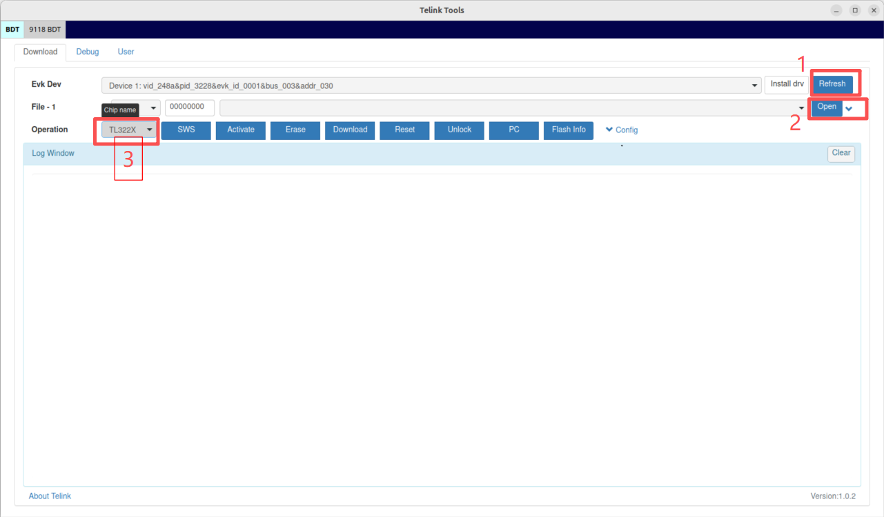
-
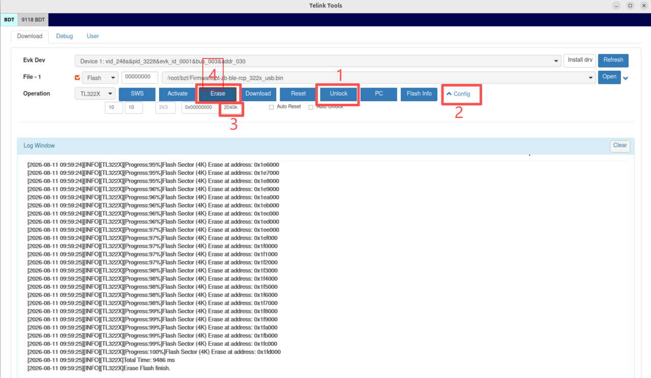
Erase the flash. Set the erase size to 2040 KB and then perform the flash erase operation. For development boards with 2 MB of external flash, the last 8 KB is reserved for SoC data, so the maximum erasable area is 2040 KB.
-
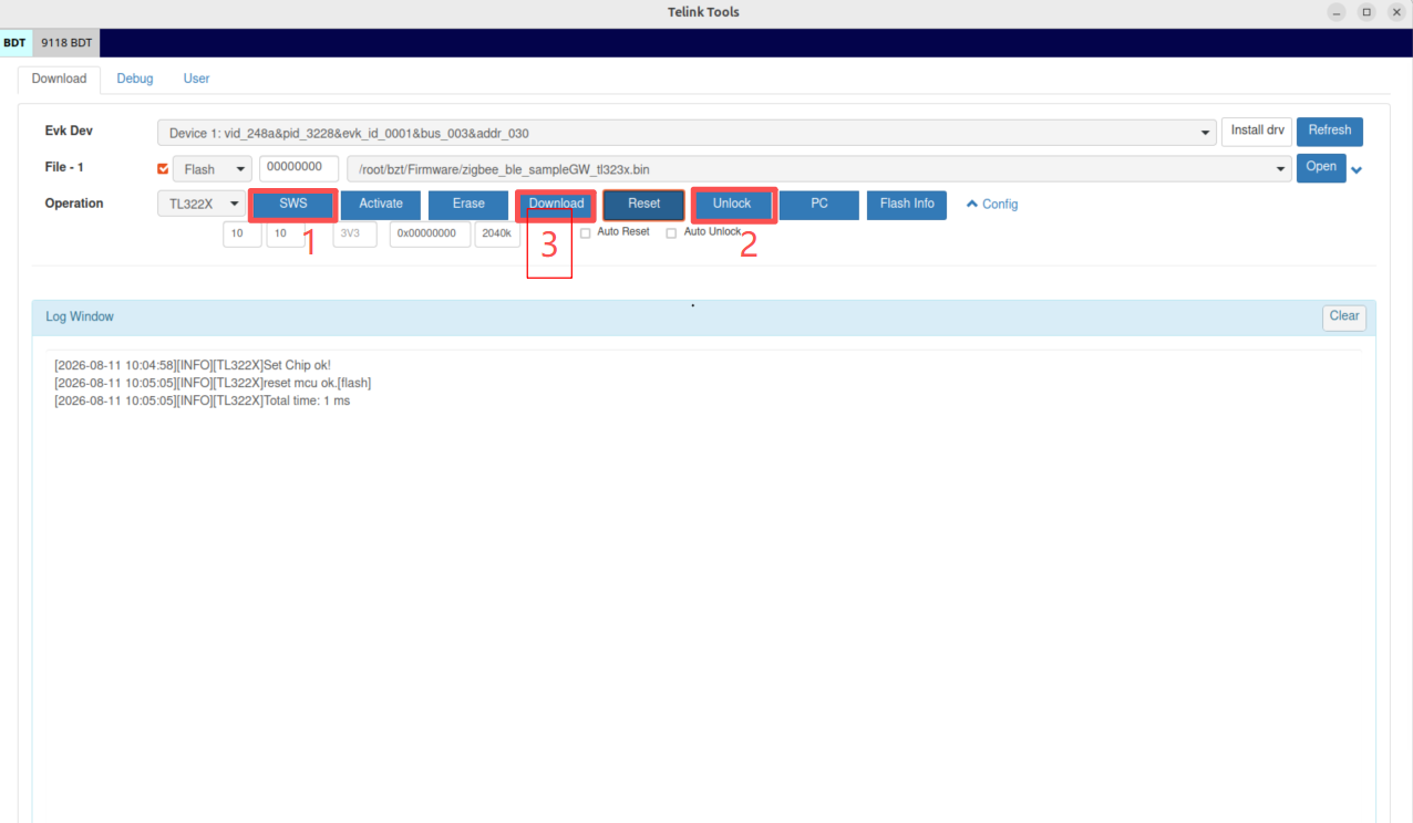
Verify SWS, unlock the flash, and download the firmware. First click SWS to confirm normal communication with the target device. Click Unlock to disable flash protection, and then click Download to flash the selected firmware to the device.
-
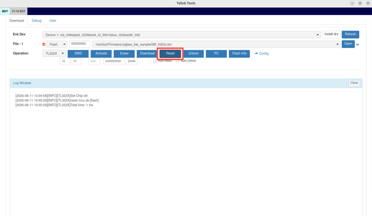
Reset the development board. After flashing is complete, power the development board back on (or press its Reset button) to start the new firmware.
Flashing the node device firmware
Flashing the BLE device
The target board is the TL3238 Dongle. See Connecting the Hardware for the hardware connections. Select the board type TL323x and the firmware zigbee_ble_sampleGW_tl323x.bin. For the detailed flashing steps, see Flashing the RCP Firmware.
Flashing the Zigbee device
The target board is the TL3238 Dongle. See Connecting the Hardware for the hardware connections. Select the board type TL323x and the firmware sampleLight_tl323x.bin. For the flashing steps, see Flashing the RCP Firmware.
Flashing the Matter over Thread device
The target board is the TL3238x development board. See Connecting the Hardware for the hardware connections, and select the board type TL323x.
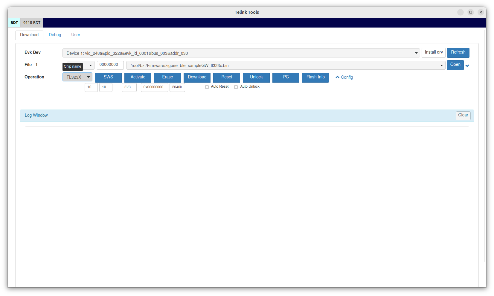
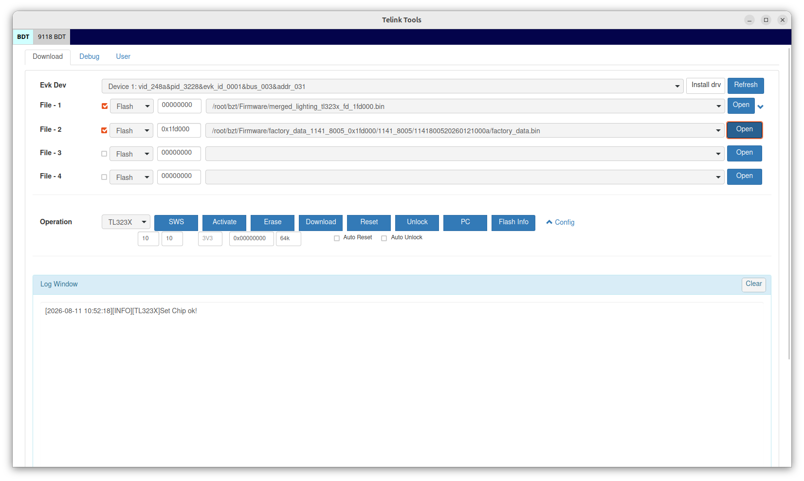
The Matter over Thread device requires two firmware images to be flashed to the target board. Click the expansion button next to Open on the menu bar.
- Select
merged_lighting_tl323x_fd_1fd000.bin, and set the flash address to0. - Open the
factory_data_1141_8005_0x1fd000/1141_8005directory, choose a folder, and locatefactory_data.bin. Set the flash address to0x1fd000.
After both firmware images are selected, click Download, and BDT will automatically flash both of them.
Verifying the example output
Host environment setup
Installing the OTBR service
Install the OTBR (OpenThread Border Router) service by following the steps in the official documentation. After installation, configure and start the OTBR service as follows:
-
Edit the configuration file to set the serial device and baud rate:
sudo nano /etc/default/otbr-agentIn the configuration file, find the following line (create it if it does not exist):
OTBR_AGENT_OPTS=""Change it to:
OTBR_AGENT_OPTS="-I wpan0 -B enp3s0 spinel+hdlc+uart:///dev/ttyACM0?uart-baudrate=115200"Note
/dev/ttyACM0is the device name. Adjust it according to the actual device name on your system. -
Restart the service:
sudo systemctl daemon-reload
sudo systemctl restart otbr-agent
sudo systemctl status otbr-agent
Installing chip-tool
The CHIP tool (chip-tool) is a Matter controller implementation. Its installation is very simple: just run the following command in a terminal:
sudo snap install chip-tool
For detailed usage instructions and more information about chip-tool, please refer to the official documentation.
Installing the ZGC tool
Zigbee Gateway Controller (ZGC) is a tool used to control Zigbee gateways. Its Linux version is provided as the package zgc_ble_controller_linux.tar.gz, together with the precompiled firmware. Complete the installation and initial configuration as follows:
- Unzip
zgc_ble_controller_linux.tar.gz. -
Run the installation command:
sudo python3 zgc_tool.py
Note
If you are running it for the first time, install the additional dependencies (bluez, python3) to complete the configuration:
sudo apt-get update
sudo apt-get install bluez python3 python3-pip libxcb-cursor0
Install the Python modules:
pip3 install csv pyserial PySide6 pandas
Commissioning and controlling the Matter device
This section describes how to start the Thread network through OTBR, and use chip-tool to commission and control the Matter device.
Starting OTBR
- Boot the host and connect the RCP device (TL3228x development board) to the host with a USB Type-C cable. Make sure the cable is inserted into the USB port at the upper right corner of the TL3228x development board.
-
Run the following command in a terminal to check whether the system has correctly recognized the two serial ports of the RCP. Under normal conditions, the output should contain two
ttyACMports:ls /dev/tty* -
Run the following command to confirm that the RCP is properly connected to the host. If the returned result does not contain
"Connection refused", the connection is successful:sudo ot-ctl stateIf the returned result contains
"Connection refused", see FAQ: RCP cannot communicate with the host. -
Run the following commands in sequence to configure and start the Thread network. Each command should return
Doneafter execution:sudo ot-ctl dataset set active 0e08000000000000000000030000144a0300000b35060004001fffe0020811111111222244440708fddead00beef00000510ffeeddccbbaa9988776655443322110003037365640102058b0410567138be961fa4dbf260cbbd420b39f00c0402a0f7f8 sudo ot-ctl ifconfig up sudo ot-ctl thread start -
Wait a moment, and then run the following command to check the gateway role. If it returns
leader, the network has been started successfully:sudo ot-ctl state -
Query the current channel of OTBR by entering the following command in the shell. The returned value should be 20. The subsequent Zigbee network configuration also needs to use the same channel.
sudo ot-ctl channelOTBR supports command-line control. For the detailed commands, see the OpenThread CLI official documentation. When using it, prepend
sudo ot-ctlto the commands.
Commissioning and controlling the Matter device
After the Thread network is running properly, commission and control the Matter device as follows.
- Power on the Matter device (TL3238x development board) to put it into the ready-to-commission state.
-
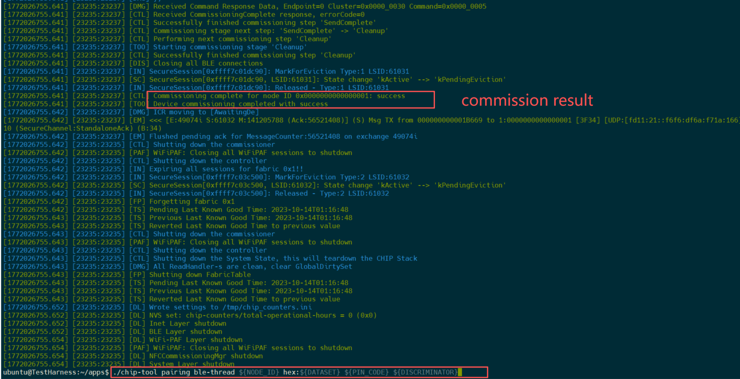
Use chip-tool to add the device to the network. Run the following command in a terminal:
chip-tool pairing ble-thread 1 hex:0e08000000000000000000030000144a0300000b35060004001fffe0020811111111222244440708fddead00beef00000510ffeeddccbbaa9988776655443322110003037365640102058b0410567138be961fa4dbf260cbbd420b39f00c0402a0f7f8 ${PIN_CODE} ${DISCRIMINATOR}Parameter description:
${PIN_CODE}and${DISCRIMINATOR}are variables that need to be replaced with the actual values. The actual values can be found in the firmware directoryFirmware\factory_data_1141_8005_0x1fd000\1141_8005\. Enter the folder wherefactory_data.binis located, and check thesummary.jsonfile:passcodecorresponds to${PIN_CODE}, anddiscriminatorcorresponds to${DISCRIMINATOR}.
-
After the device is successfully commissioned, you can control the Matter device with chip-tool. After running the following command, you should be able to observe the red, blue, and green LEDs on the TL3238x development board turning on or off:
chip-tool onoff toggle 1 1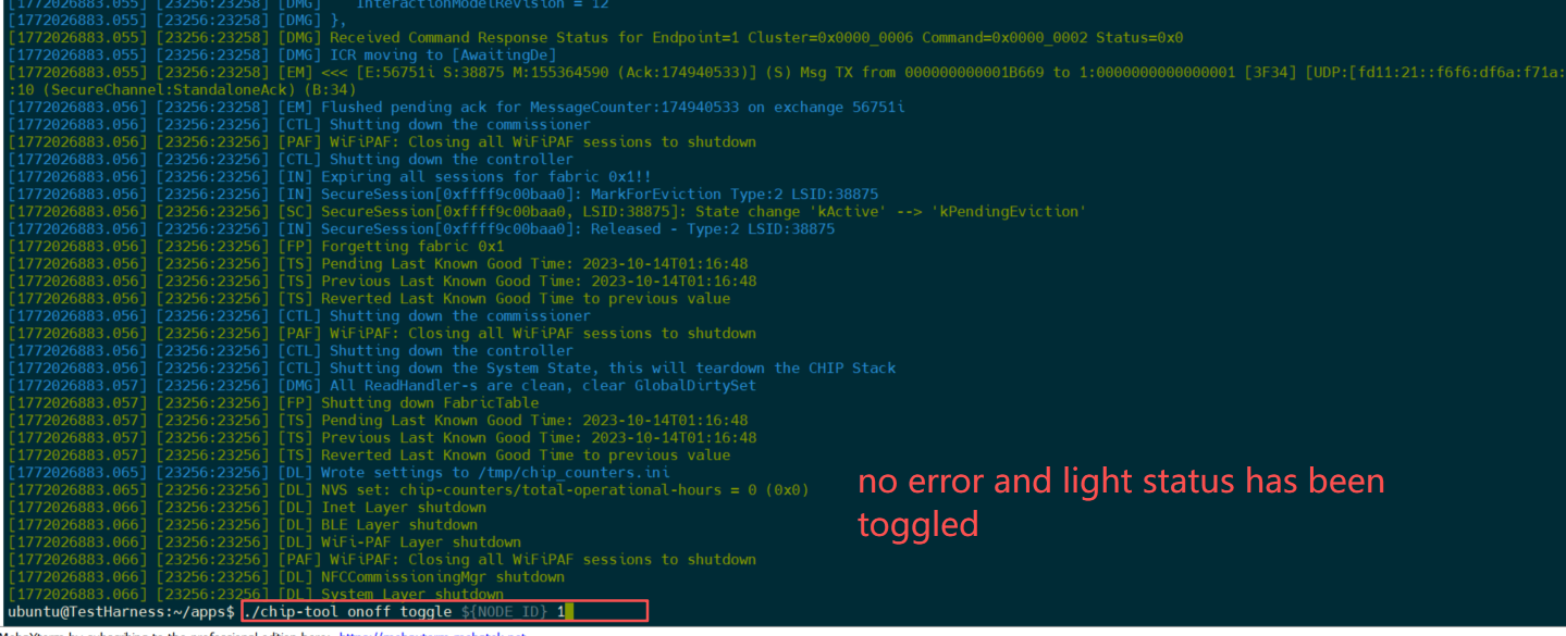
Commissioning and controlling Zigbee devices
This section describes how to start Zigbee with the ZGC tool, and commission and control the Zigbee device (TL3238 Dongle).
- Open a new command-line terminal on the host and run the following commands to enter the directory of the ZGC tool and start it:
cd bzt/tool/zgc_ble_controller_linux/ python3 zgc_tool.py - After the program starts, the ZGC GUI will pop up on the desktop. Configure it as follows:
- Port selection: Select the
ttyACMport with the larger number - Baud rate: Set it to
115200 - Function checkboxes:
- Check the "bleHci" option at the lower left
- Check the "scroll to bottom" option on the left
- Connection: Click the "Open" button to complete the serial connection.
- Port selection: Select the
-
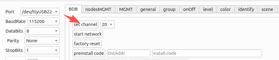
In the ZGC tool interface, click the "BDB" tab. The Zigbee network channel must be set to the same channel as the Matter network (e.g., channel 20) to ensure wireless communication compatibility.
-
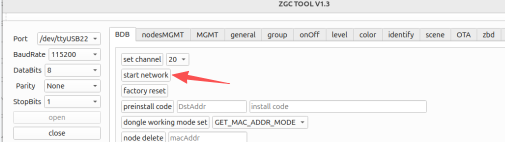
Click "start network", and ZGC will start the Zigbee network. Once it starts successfully, the green LED indicator on the RCP device (TL3228x development board) will light up, indicating that the network is running normally.
-
Power on the Zigbee device. After a moment, the green LED indicator on the device will light up, indicating that it has successfully joined the Zigbee network.
-
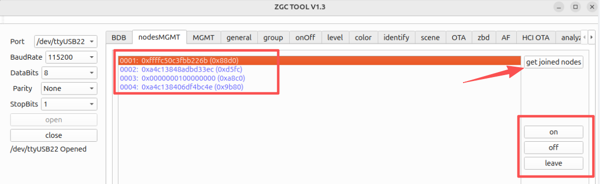
In the ZGC interface, select the "nodesMGMT" tab and then click "get joined nodes". The interface will list all device nodes that have joined the current network. Select a target device from the list, and then click the "on"/"off" buttons to control the blue LED indicator on the Zigbee device.
Connecting to the BLE device
This section describes how to use the ZGC tool to connect to the BLE device (TL3238 Dongle) over Bluetooth Low Energy (BLE).
- Open a new command-line terminal on the host and run the following commands to enter the directory of the ZGC tool and start it:
cd bzt/tool/zgc_ble_controller_linux/ python3 zgc_tool.py -
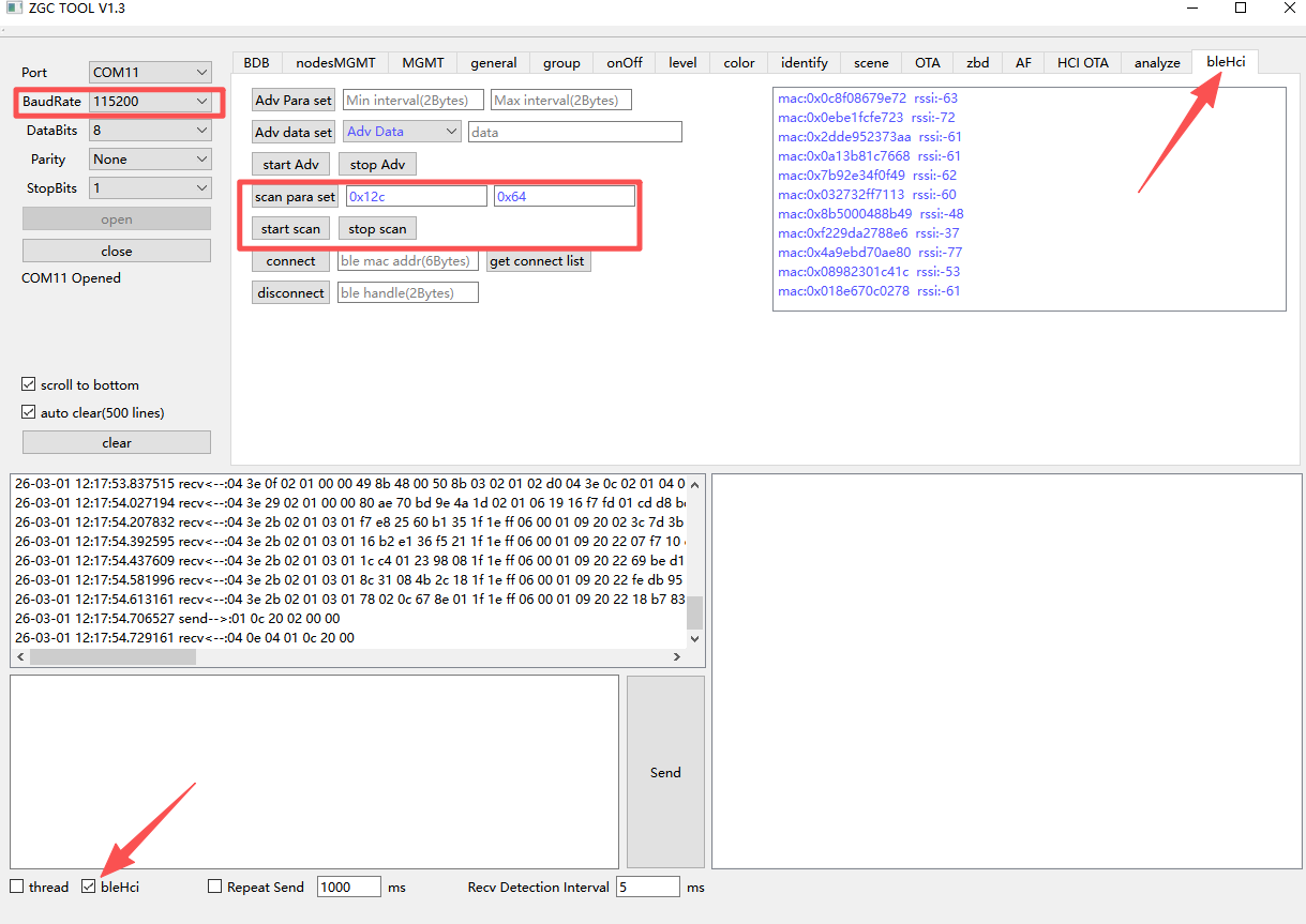
After the program starts, the ZGC GUI will pop up on the desktop. Configure it as follows:
- Port selection: Select the
ttyACMport with the larger number - Function checkboxes:
- Check the "bleHci" option at the lower left
- Check the "scroll to bottom" option on the left
- Connection: Click the "Open" button to complete the serial connection.
- Port selection: Select the
-
Power on the BLE device to put it into the discoverable state.
-
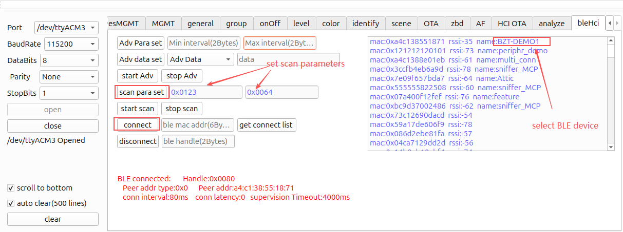
In the ZGC interface, select the "bleHci" tab on the right. Enter
0x0123and0x0064in the input boxes after "scan para set", and then click "scan para set" to complete the parameter configuration.Note
Make sure to complete Step 3 (powering on the device) before performing the parameter settings in this step, so that the device can be scanned properly.
-
Click "start scan" to start scanning. The receiving interface will display a large number of HCI command logs. After about 10 seconds, click "stop scan" to stop scanning.
-
In the scan results, find and select the device named "BZT-DEMO1", and then click the "connect" button. After the connection succeeds, the interface will display "BLE connected". If the connection fails, reselect the device and try to connect several more times. See FAQ: BZT Demo cannot connect to the BLE device.
FAQ
RCP cannot communicate with the host
Symptom: When OTBR is started, entering an OTBR control command returns the error "Connection refused".
Solution:
- Restart the RCP.
- Enter the following command in the shell to check whether two ttyACMx nodes are enumerated.
ls /dev/tty* - Open the
otbr-agentconfiguration file, check whether the spinel port number is the ttyACMx node with the smaller number, and update it to the actual node.sudo nano /etc/default/otbr-agent OTBR_AGENT_OPTS="-I wpan0 -B enp3s0 spinel+hdlc+uart:///dev/ttyACM0?uart-baudrate=115200" - Restart the OTBR service.
sudo systemctl daemon-reload
sudo systemctl restart otbr-agent
sudo systemctl status otbr-agent
BZT Demo cannot connect to the BLE device
Symptom: The ZGC tool cannot scan the BLE device's advertisements, making it impossible to connect to the BLE device.
Solution:
- Restart the BLE device.
- Make sure the scan parameters are set correctly, click start scan again, wait 10 seconds, and then click stop scan. Wait for the BLE device list on the right to refresh.
- Select the "BZT-DEMO1" device to connect.
Community and resources
| Resource | Description |
|---|---|
| Telink official forum | Technical communication and support |
| Telink official website | Product center |
| Telink documentation website | Documentation center |