Telink Low-Latency Audio Gamepad Getting Started
Overview
This document helps you quickly complete firmware flashing and functional verification of the low-latency audio gamepad example project. This example is based on the TL322x (RISC-V) SoC and uses the Telink eXtra Throughput and Reliability Link layer (TXTRLL) to implement a low-latency game controller solution, delivering up to 8 kHz HID report rate with optional LC3+ audio functionality.
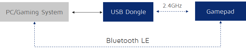
Verification modes
This solution supports three working modes; different verification scenarios are used to verify different modes:
| Working mode | Function combination | HID report rate | Description |
|---|---|---|---|
| HID Only | 2.4G HID | 8 kHz | 2.4G RF time slot is exclusively occupied; the most stable report rate |
| HID + BLE | 2.4G HID + BLE | Approx. 7.7–7.8 kHz | BLE is enabled, RF time slots are shared with 2.4G |
| HID + Audio + BLE | 2.4G HID + 2.4G Audio + BLE | Approx. 900 Hz | Audio and BLE operate simultaneously; report rate is affected by BLE preemption |
Verification scenarios overview
This document provides three verification scenarios. You can select a scenario based on the hardware you have:
- Scenario 1: TL322x development kit — verifies HID Only working mode.
- Scenario 2: TL322x PA Dongle development board — verifies HID + Audio + BLE working mode.
- Scenario 3: Telink gamepad reference design — verifies the three working modes in the table above.
The development kits and Telink programmers can be purchased from Mouser or DigiKey; Dongles and Telink gamepad reference design is reserved for deep cooperation projects. Interested partners are welcome to contact us for detailed consultation.
Note
Click here to download the pre-built firmware.
Each scenario includes the complete workflow of "Hardware and software preparation → Hardware connection → Firmware flashing → Verification." Scenarios 1 and 2 are flashed via BDT (see Appendix A); the physical prototype in Scenario 3 must be flashed via BDT for the first time, and subsequent firmware upgrades can use USB OTA.
Verification scenario 1: TL322x development kit verification
Applicable scenario: Use the officially sold TL322x development kit to verify the high report rate and pairing function of the XTRL 8K gamepad in only HID mode. This scenario disables Audio and BLE; 2.4G RF time slots are exclusively occupied, and the HID report rate is stable at 8 kHz.
In the kit, the TL322x development board emulates the Gamepad side, and the TL322x Dongle development board emulates the Dongle side.
Hardware and software preparation
Hardware checklist
| Hardware type | Model/specification | Quantity | Description |
|---|---|---|---|
| PC | Windows 10/11, Linux, or macOS | 1 | Used as the development host, running programming & debugging software, test software, etc. (Windows is used as an example in this document) |
| TL322x development kit | TL322x development board | 1 | Emulates the Gamepad (controller) side |
| TL322x Dongle development board | 1 | Emulates the Dongle (receiver) side | |
| Programmer V3 | 1 | Programmer used to flash firmware to the development boards. | |
| Antenna | 1 | Ensures normal wireless communication of the development boards | |
| USB Type-C cable | 1 | Connects PC to the Gamepad-side development board for power supply and data reporting. | |
| Cables | Dupont wires | Several | Connect the programmer to the debug/flash interface on the development boards. |
| Mini-USB cable | 1 | Connects PC to the programmer, providing the flashing channel. |
Software and firmware checklist
| Software/firmware | Name | Description |
|---|---|---|
| Flashing tool | Burning and Debugging Tool (BDT) | Dedicated programming & debugging software for flashing firmware to development boards. Download, installation, and usage instructions are provided in Appendix A. |
| Pre-built firmware | firmware_merged_gamepad_hid_only.bin |
HID-only firmware for the TL322x development board (Gamepad side) |
firmware_merged_dongle_hid_only.bin |
HID-only firmware for the TL322x Dongle development board | |
| Test tool | Mouse & keyboard report rate test software | Multi-function test software for verifying report rate and gamepad input. |
Hardware connection
Following Hardware connection between programmer and development board, perform the same hardware connection on each of the two development boards separately (flash one board at a time; complete one before moving to the other).
Firmware flashing
The two development boards are flashed with different firmware. For detailed flashing steps, refer to BDT flashing procedure.
Verification
Hardware reconnection
After flashing is complete, reconfigure the hardware connections for interoperability verification:
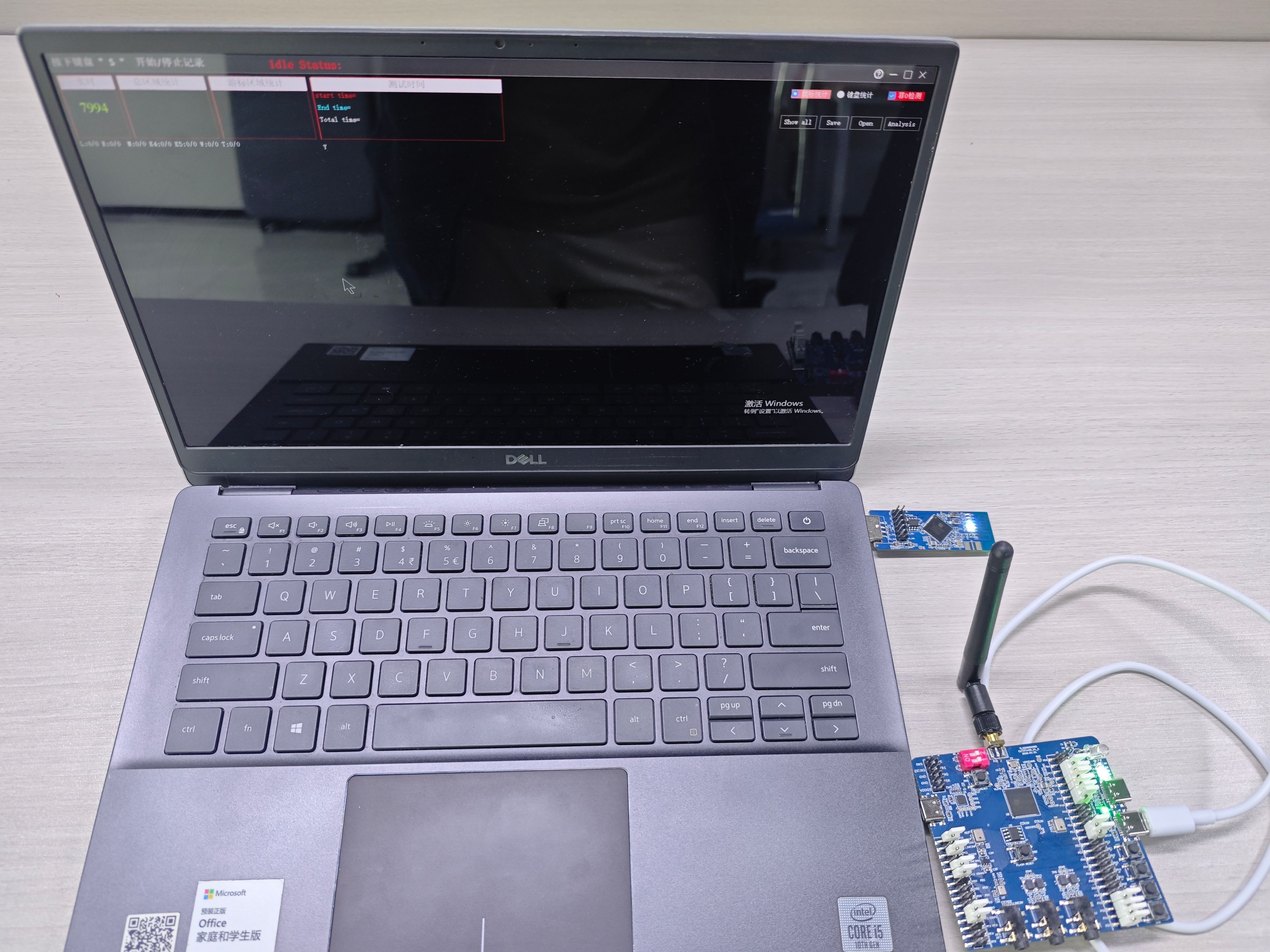
- TL322x Dongle development board: plug directly into a USB port on the PC.
- TL322x development board: only needs to be powered on via the programmer (or any 3.3V power supply); no PC connection required.
- Install the antenna: make sure the rubber duck antenna is properly attached to the TL322x development board; otherwise, poor wireless signal quality may cause pairing failure.
Pairing
- Power on both development boards. The devices automatically complete pairing within 5 seconds after power-on; no manual operation is required throughout the process.
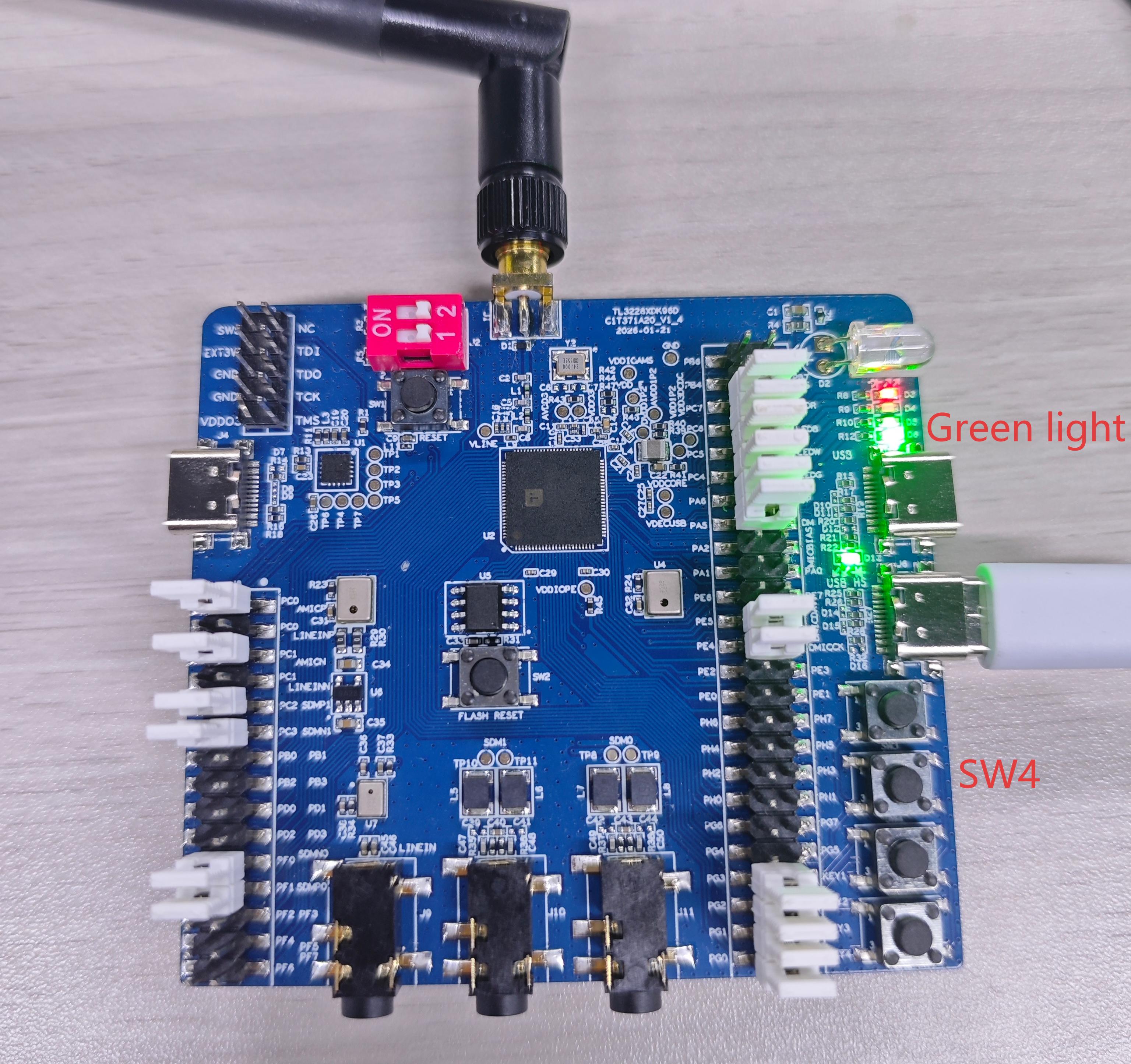
- During pairing, the green LED indicator blinks rapidly; after successful pairing, the white LED indicator remains solid on. If the white LED does not stay on, pairing has not succeeded; refer to the Pairing failure troubleshooting section.
- After the first successful pairing, subsequent use does not require re-pairing. After power-on, the TL322x development board (Gamepad side) automatically attempts to connect to the previously paired Dongle device for fast reconnection.
Note
After successful pairing, press the SW4 button on the Gamepad side to start/pause HID reporting. During reporting, the green LED remains solid on; during pause, the green LED turns off.
HID function verification
- On the PC, press
Win + R, typejoy.cpl, and open the Game Controllers panel to confirm the PC recognizes the gamepad device. -
Use the mouse & keyboard report rate test software to verify the report rate on the gamepad side. You may select any test software you are familiar with.
Note
When testing the report rate, close all other applications to avoid CPU resource contention that may affect test results.
-
Open the mouse & keyboard report rate test software on the PC. The real-time report rate of the gamepad is displayed. In HID Only working mode, the report rate is stable around 8 kHz.
Pairing failure troubleshooting
If the first pairing attempt fails or the gamepad device is not recognized on the PC, troubleshoot in the following order:
- Check the antenna: if the TL322x development board does not have an antenna installed, 2.4G signal transmit/receive quality is poor and pairing may fail. It is recommended to attach the rubber duck antenna to the development board.
- Check the distance: the two development boards should not be too far apart; a distance within 0.5 m is recommended.
- Check the PC environment: close applications consuming CPU/USB resources, then power cycle and re-pair.
Verification scenario 2: TL322x PA Dongle development board verification
Use the TL322x PA Dongle development board to verify all functions of the XTRL 8K gamepad when working in the 2.4G HID + 2.4G Audio + BLE mode. This scenario enables Audio and BLE; affected by BLE preemption, the HID report rate is approximately 900 Hz.
The two development boards emulate the gamepad side and dongle side respectively:
- The gamepad side supports 3.5mm headphone audio output and BLE;
- The dongle side connects to the PC via USB and reports HID and UAC audio devices.
Hardware and software preparation
Hardware checklist
| Hardware type | Model/specification | Quantity | Description |
|---|---|---|---|
| PC | Windows 10/11, macOS, or Linux | 1 | Used as the development host, running programming & debugging software, test software, etc. (Windows is used as an example in this document) |
| Development board | TL322x PA Dongle | 2 | One emulates the gamepad side, one emulates the dongle side; can be used to verify Audio / BLE / HID functions. |
| Telink Programmer | Programmer V3 | 1 | Used to flash firmware to the development boards. |
| Cables | Mini-USB cable | 1 | Connects PC to the programmer, providing the flashing channel. |
| Dupont wires | Several | Connect the programmer to the development boards. | |
| Headphones or speakers | 3.5mm wired headphones or speakers | 1 | Used for Audio function verification (plug into the headphone jack on the gamepad-side board, not the PC audio jack) |
| BLE scanning device | Android/iOS phone with nRF Connect app installed | 1 | Used for BLE verification |
Software and firmware checklist
| Software/firmware | Name | Description |
|---|---|---|
| Flashing tool | BDT | Dedicated programming & debugging software for flashing firmware to target development boards. Download, installation, and usage instructions are provided in Appendix A. |
| Pre-built firmware | firmware_merged_gamepad.bin |
Gamepad-side firmware |
firmware_merged_dongle.bin |
Dongle-side firmware | |
| Test tool | Mouse & keyboard report rate test software | Multi-function test software for verifying report rate and gamepad input |
| BLE scanning tool | nRF Connect app | Mobile BLE scanning/connection tool (Search and download from Android/iOS app stores) |
Hardware connection
Following Hardware connection between programmer and development board, perform the same hardware connection steps on each of the two development boards separately (flash one board at a time; complete one before moving to the other).
Firmware flashing
The two development boards are flashed with different firmware. For detailed flashing steps, refer to BDT flashing procedure.
Verification
Hardware reconnection
After flashing is complete, reconfigure the hardware connections for interoperability verification:
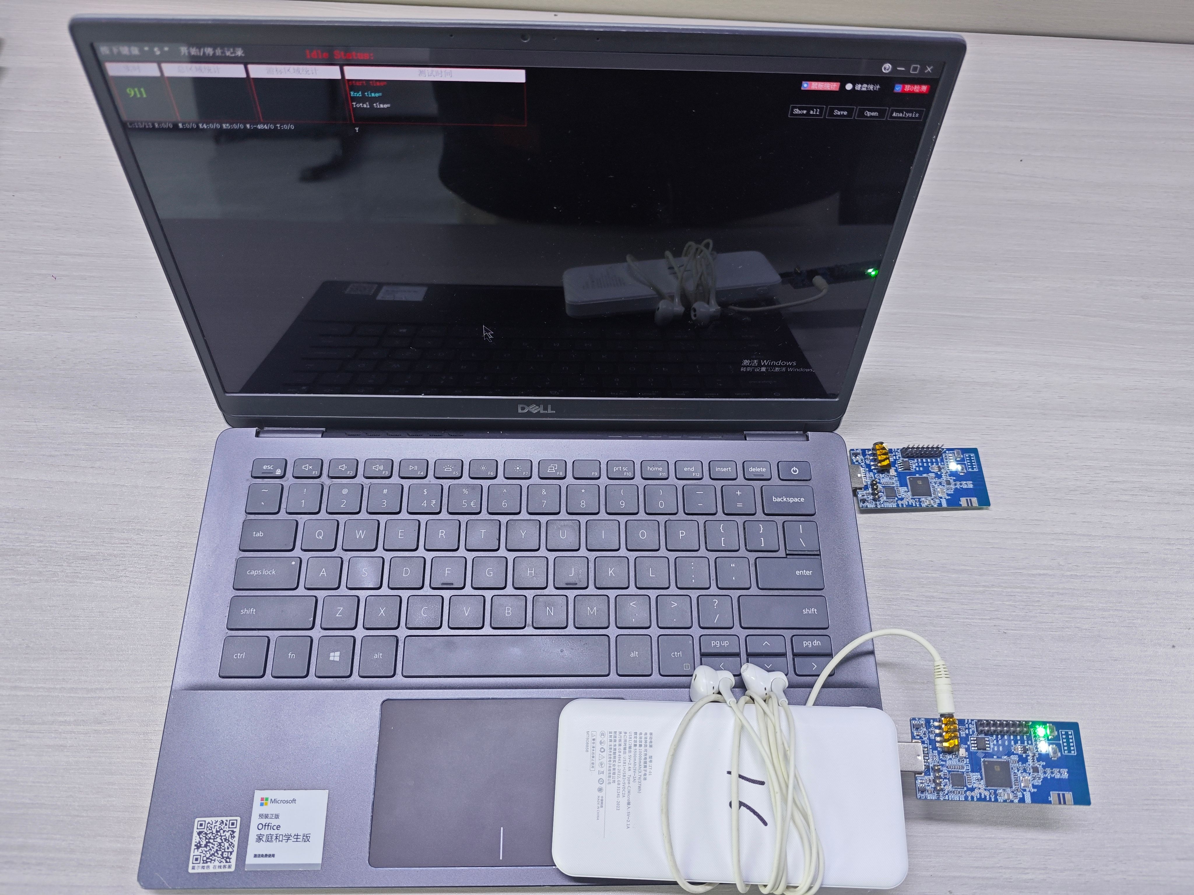
- Dongle-side development board: disconnect Dupont wires and plug directly into a USB port on the PC.
- Gamepad-side development board: power on via the programmer or 3.3V power supply.
- Audio connection (if verifying audio): plug 3.5mm headphones into the headphone jack on the gamepad-side development board (not the PC audio jack).
Pairing
- Power on both development boards. The devices automatically complete pairing within 5 seconds after power-on; no manual operation is required throughout the process.
- During pairing, the yellow LED indicator blinks rapidly; after successful pairing, the white LED on the development board remains solid on.
- After one successful pairing, subsequent power-ons use reconnection: after power-on, the gamepad side automatically attempts to connect to the previously paired dongle without re-pairing.
- After successful pairing, the gamepad HID device is recognizable on the PC.
Note
After successful pairing, press the SW2 button on the Gamepad side to start/pause HID reporting. During reporting, the green LED remains solid on; during pause, the green LED turns off.
HID function verification
- On the PC, press
Win + R, typejoy.cpl, and open the Game Controllers panel to confirm the PC recognizes the gamepad device. - Open the mouse & keyboard report rate test software, in the 2.4G HID + 2.4G Audio + BLE mode, the report rate is stable around 900 Hz. For detailed verification methods, refer to Scenario 1: HID function verification.
BLE verification
- Open nRF Connect on the phone.
- Tap Scan to start scanning and discover the BLE device of the XTRL 8K gamepad.
- Tap Connect to connect to the device.
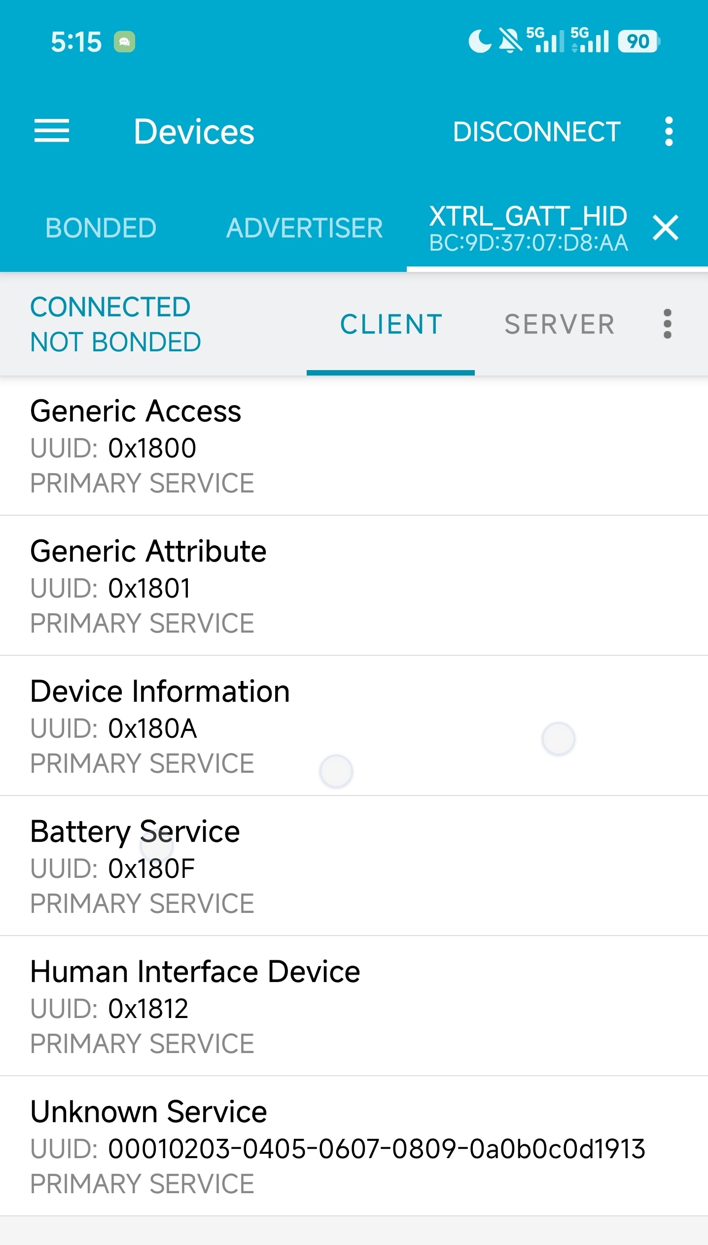
- After successful connection, view the GATT services and confirm that BLE GATT HID is functioning normally.
Audio function verification (LC3+ and USB UAC)
Audio data flow: PC → dongle (USB UAC audio input) → 2.4G wireless transmission → output from gamepad side to 3.5mm headphones
- Confirm that the dongle-side development board is connected to the PC via USB and the gamepad-side development board has been paired successfully.
- Plug 3.5mm headphones into the headphone jack on the gamepad-side development board (not the PC audio jack).
- On the PC, right-click the speaker icon in the taskbar → Playback Devices or Sound Settings, and check whether a new audio output device appears (the UAC device reported by the Dongle-side development board via USB).
- Select the audio device corresponding to the dongle-side development board as the default output.
- Play music or an audio test tone and confirm that audio data is transmitted wirelessly via 2.4G to the Gamepad side and can be heard from the headphones.
Verification scenario 3: Telink gamepad reference design verification
Using the Telink gamepad reference design, the following three working modes can be verified:
- HID Only: 2.4G RF time slots exclusively occupied; HID report rate stable at 8 kHz.
- HID + BLE: 2.4G HID and BLE online simultaneously; affected by BLE timing, HID report rate is approx. 7.7–7.8 kHz.
- HID + Audio + BLE: 2.4G HID, 2.4G Audio, and BLE online simultaneously; HID report rate is approx. 900 Hz.
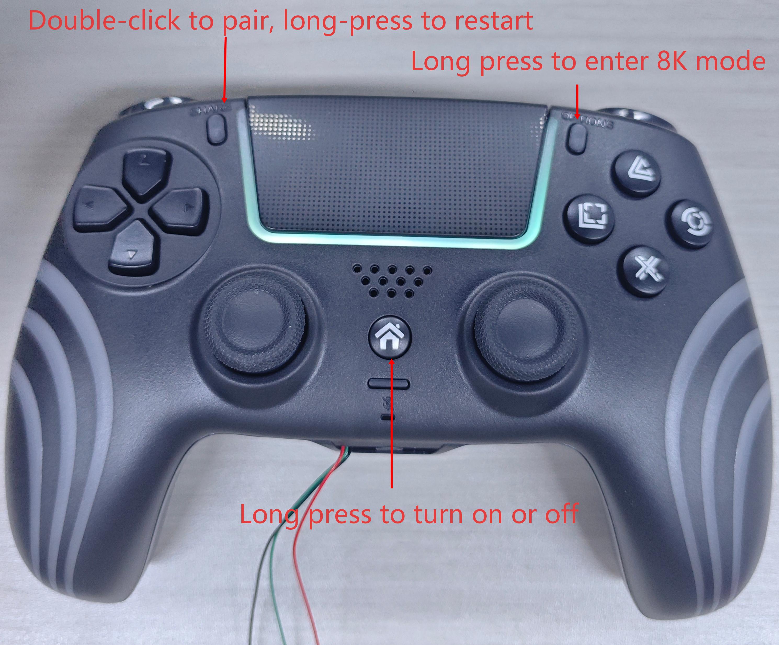
The pre-built firmware for the physical gamepad has BLE functionality integrated. The HID Only working mode verification method is the same as in Scenario 1; this chapter focuses on the other two working modes verification process. The physical gamepad is shown below:
Note
The functions of the three buttons in the photo are fixed actions in the pre-built firmware; triggering them executes the corresponding behavior.
Hardware and software preparation
Hardware checklist
| Hardware type | Model/specification | Quantity | Description |
|---|---|---|---|
| PC | Windows 10/11, macOS, or Linux | 1 | Used as the development host, running programming & debugging software, test software, etc. (Windows is used as an example in this document) |
| Physical gamepad prototype | Telink gamepad prototype | 1 | Gamepad side, used to verify Audio / BLE / HID functions |
| Dongle bundled with gamepad prototype | 1 | Dongle side, the wireless Dongle bundled with the gamepad | |
| Telink programmer | Programmer V3 | 1 | Used to flash firmware to the development boards. |
| Cables | Mini-USB cable | 1 | Connects PC to the programmer, providing the flashing channel. |
| Dupont wires | Several | Connect the programmer to the flashing target (development board / physical gamepad). | |
| USB Type-C cable | 1 | Connects PC to the physical gamepad for power supply and data reporting. | |
| Headphones/speakers | 3.5mm wired headphones or speakers | 1 | Used for Audio function verification (plug into the headphone jack on the gamepad, not the PC audio jack) |
| BLE scanning device | Android/iOS phone with nRF Connect app installed | 1 | Used for BLE verification |
Software and firmware checklist
| Software/firmware | Name | Description |
|---|---|---|
| Flashing tool | BDT | Dedicated programming & debugging software for flashing firmware to target development boards. Download, installation, and usage instructions are provided in Appendix A. |
| USB OTA upgrade package (for subsequent firmware upgrades only) | gamepad_ota package |
Used for subsequent firmware upgrades of the physical prototype; contains the upgrade script and the upgrade tool (see USB OTA upgrade method); no wire soldering is required. First-time flashing cannot use USB OTA and must be done via BDT. |
| Pre-built firmware | firmware_gamepad_8k.bin |
Physical gamepad-side firmware (used in HID only mode) |
firmware_dongle_8k.bin |
Dongle-side firmware (used in HID only mode) | |
firmware_gamepad.bin |
Physical gamepad-side firmware (used in HID + BLE or HID + Audio + BLE mode) | |
firmware_dongle.bin |
Dongle-side firmware (used in HID + BLE or HID + Audio + BLE mode) | |
| Test tool | Mouse & keyboard report rate test software | Multi-function test software for verifying report rate and gamepad input |
| BLE scanning tool | nRF Connect app | Mobile BLE scanning/connection tool (search and download from Android/iOS app stores) |
Hardware connection
Firmware writing for the physical prototype falls into two cases: the first-time flashing can only be done via BDT, while subsequent firmware upgrades can use USB OTA.
Complete the corresponding connection according to your actual situation:
Option A: BDT wire flashing (first-time flashing)
Following Hardware connection between programmer and development board, perform the same hardware connection steps on the gamepad prototype and the bundled Dongle development board separately (flash one at a time; complete one before moving to the other).
Option B: USB OTA upgrade (only for physical prototypes that have completed first-time flashing)
- Gamepad side: use a USB cable to connect the Gamepad's Type-C port to the PC.
- Dongle side: plug the Dongle directly into a USB port on the PC.
For details, see USB OTA upgrade method.
Firmware flashing
Option A: BDT wire flashing (must be used for first-time flashing)
A factory prototype has no OTA-capable upgrade program inside, so the first-time flashing cannot use USB OTA and must be completed via the programmer. For detailed flashing steps, refer to BDT flashing procedure.
Option B: USB OTA upgrade method (for physical prototypes)
This applies to firmware upgrades for the physical Gamepad and Dongle that have already completed first-time flashing; no wire soldering is required.
Note
The Gamepad and Dongle firmware cannot be flashed interchangeably: the two have different hardware, and flashing the wrong firmware will render the device unusable. If the wrong firmware has been flashed, re-flash it via the wired method (see BDT flashing procedure) before USB OTA can be used again.
Step 1: Prepare the upgrade files
The OTA upgrade package (the gamepad_ota folder) contains four files in total: one upgrade script, one firmware to be upgraded (example), and two upgrade tool support files.
| File | Description |
|---|---|
dfu_update.bat |
Upgrade script |
firmware_merged_gamepad.bin |
Firmware to be upgraded (example only; the firmware you plan to flash prevails) |
usb_dfu.exe |
USB OTA upgrade tool |
hidapi.dll |
Dependency library of the upgrade tool |
The firmware_merged_gamepad.bin in the table above is only an example firmware. During an actual upgrade, replace the firmware to be upgraded in the package with the firmware file (.bin) you plan to flash. There is no fixed requirement for the firmware file name, but it must correspond to the target device (Gamepad or Dongle).
Note
The firmware file name referenced in the upgrade script dfu_update.bat must be consistent with the file name of the firmware actually used for upgrading. After replacing the firmware, update the file name in the script accordingly.
Step 2: Connect the device and enter upgrade mode
- Connect the device to be upgraded (Gamepad or Dongle) to the PC.
- Press the reset/upgrade button on the device.
- Double-click the
dfu_update.batscript promptly to start the upgrade. Note: if no upgrade action is taken within 5 s after pressing the reset button, the device will automatically restart.
Step 3: Wait for the upgrade to complete
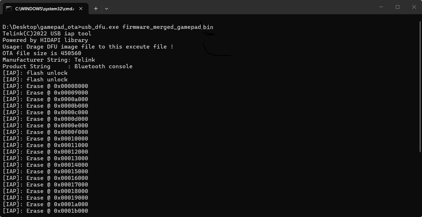
After the script runs, a command-line window pops up on the PC and the upgrade proceeds normally. The upgrade process completes Flash unlocking, page-by-page erasing, and firmware writing in sequence:
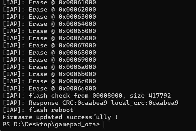
Wait for the upgrade process to finish. The command-line window displays Firmware updated successfully !, the device restarts automatically, and the upgrade is complete.
Verification
Hardware reconnection
After flashing is complete, reconfigure the hardware connections for interoperability verification:
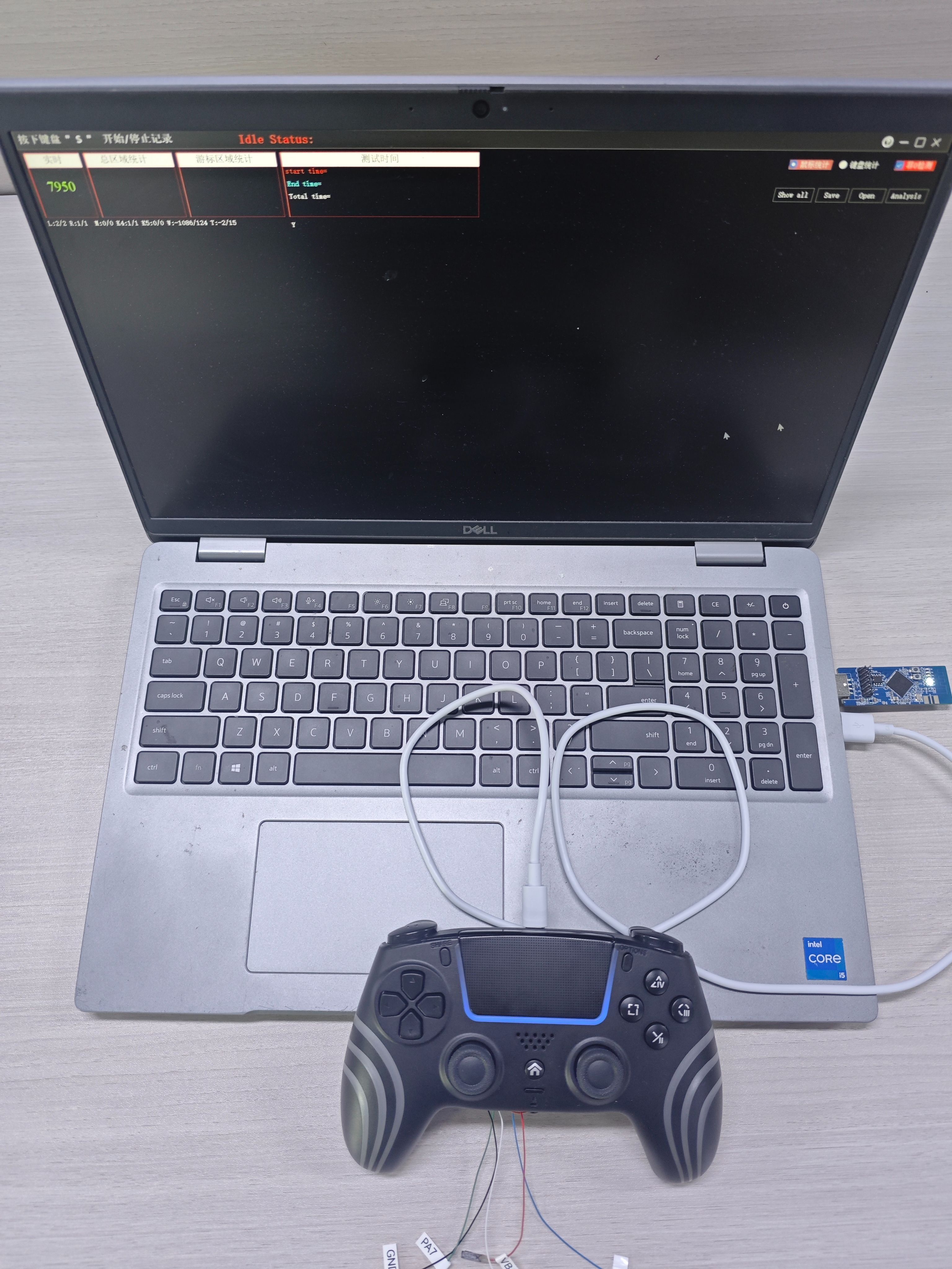
Pairing
- Power on the Dongle and the gamepad respectively. The devices automatically complete pairing within 5 seconds after power-on; no manual operation is required throughout the process.
- During pairing, the yellow LED on the Dongle board blinks rapidly, and the LED on the Gamepad alternates between purple and cyan; after pairing succeeds or times out, the yellow LED on the Dongle development board turns off. The white LED stays solid on when the Dongle is paired successfully.
- After one successful pairing, subsequent power-ons use reconnection: after power-on, the gamepad side automatically attempts to connect to the previously paired Dongle.
HID Only verification
The HID Only function verification method is the same as in Scenario 1; refer to Scenario 1: HID function verification:
- On the PC, press
Win + R, typejoy.cpl, and open the Game Controllers panel to confirm the PC recognizes the gamepad device. - Open the mouse & keyboard report rate test software; in HID Only mode, the report rate should be stable around 8 kHz.
Note
When testing the report rate, close other applications to avoid CPU resource contention that may affect test results.
HID + BLE verification
In HID + BLE mode, 2.4G HID and BLE are online simultaneously:
- HID function: On the PC, press
Win + R, typejoy.cpl, and open the Game Controllers panel to confirm the gamepad device is recognized; open the mouse & keyboard report rate test software to check the report rate, which should be approx. 7.7–7.8 kHz. - BLE function:
- Open the nRF Connect app on the phone.
- Tap Scan to start scanning and discover the BLE device of the XTRL 8K gamepad.
- Tap Connect to connect to the device.
- After successful connection, view GATT services and confirm BLE GATT HID is working normally.
HID + Audio + BLE verification
In HID + Audio + BLE mode, 2.4G HID, 2.4G Audio, and BLE are online simultaneously; for details refer to Scenario 2: HID + Audio + BLE mode verification:
- HID function: Open the mouse & keyboard report rate test software to check the report rate, which should be approx. 900 Hz.
- Audio function (LC3+ and USB UAC):
Audio data flow: PC → Dongle (USB UAC audio input) → 2.4G wireless transmission → output from the gamepad side to 3.5mm headphones
- Plug 3.5mm headphones into the headphone jack on the gamepad side (not the PC audio jack).
- On the PC, right-click the speaker icon in the taskbar → Playback Devices or Sound Settings, and check whether a new audio output device appears (the UAC device reported by the Dongle side via USB).
- Select the audio device corresponding to the Dongle side as the default output.
- Play music or an audio test tone and confirm that audio data is transmitted wirelessly via 2.4G to the gamepad side and can be heard from the headphones.
- BLE function: Open the nRF Connect app on the phone, then scan for and connect to the gamepad's BLE device via nRF Connect.
Mode switching
The gamepad reference design uses the Option button on the gamepad to switch between HID + BLE and HID + Audio + BLE modes. When switching, the LED indicator on the gamepad side provides feedback on the current mode through different lighting effects:
| Mode | Function combination | HID report rate | LED effect | Action |
|---|---|---|---|---|
| HID + BLE | 2.4G HID + BLE | Approx. 7.7–7.8 kHz | Cyan solid or blue blinking (press Option button to toggle lighting effect) | Automatically draws a square pattern on the PC after switching |
| HID + Audio + BLE | 2.4G HID + 2.4G Audio + BLE | Approx. 900 Hz | Cyan solid or blue blinking (press Option button to toggle lighting effect) | None |
Appendix A: Complete firmware flashing procedure
This appendix describes the complete firmware flashing procedure for all three verification scenarios; all scenarios reference this appendix for flashing.
A.1 BDT installation
BDT is a portable (installation-free) programming & debugging software provided by Telink, used to flash firmware to the target chip.
-
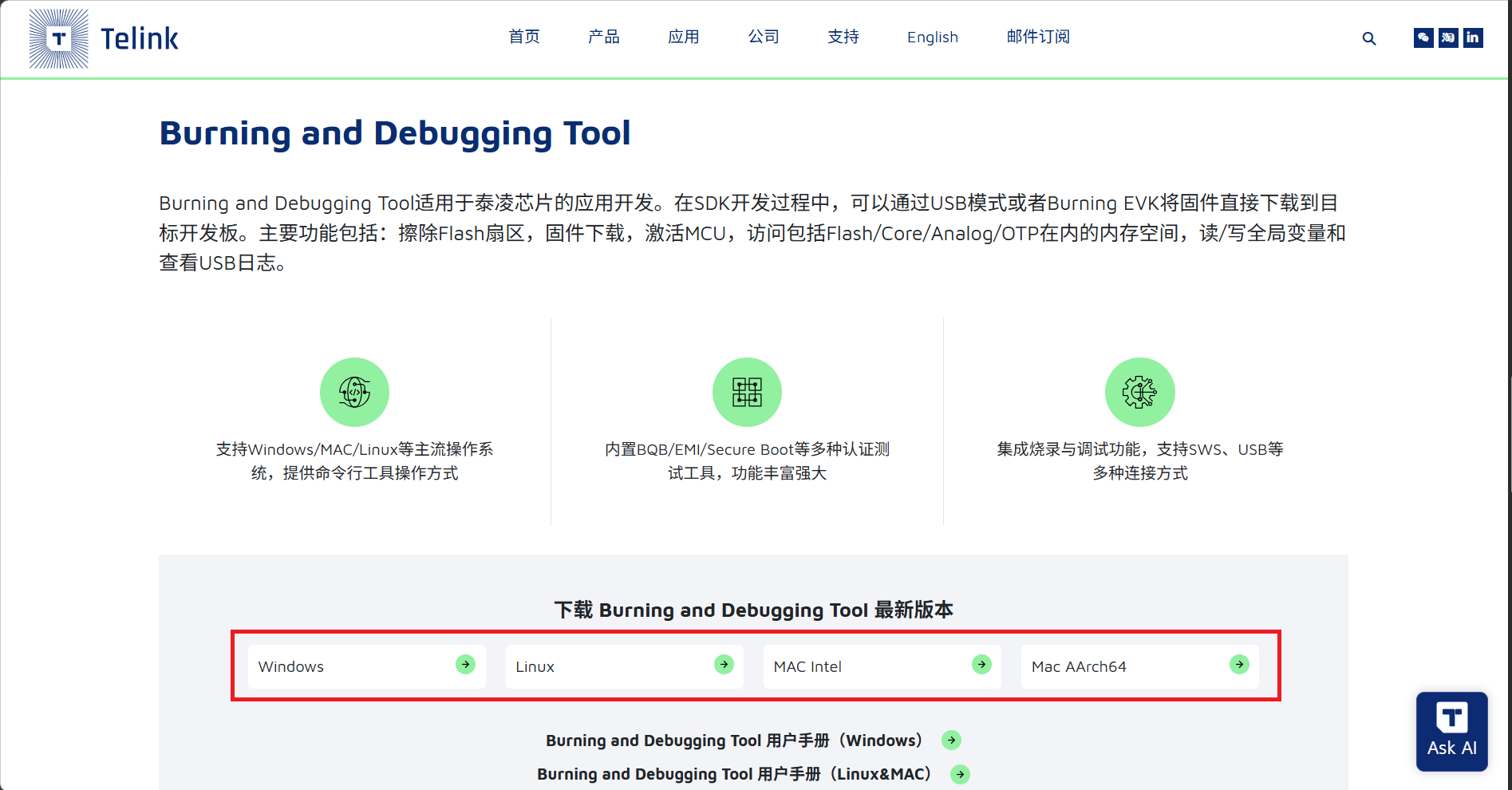
Download the BDT tool.
Visit the Telink Developer Center - Development Tools and download the tool package corresponding to your operating system.
-
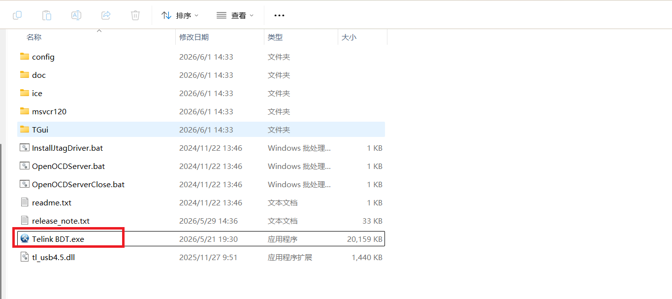
Extract the tool package. BDT is a portable tool; simply extract it to use. Using Windows as an example:
- Extract the downloaded package to a custom path, e.g.,
C:\Telink\BDT. - Navigate to the extracted release directory, e.g.,
C:\Telink\BDT\release_v5.9.2. - Double-click Telink BDT.exe to launch the tool.
- Extract the downloaded package to a custom path, e.g.,
-
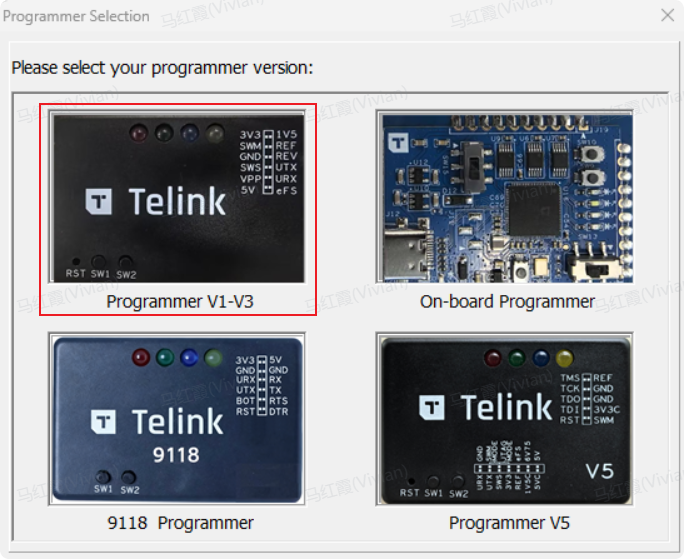
Select the programmer version and chip compatibility.
BDT supports multiple versions of programmers; you must select the version corresponding to the SoC model in use. The TL322x development boards referenced in this document use the Programmer V3:
A.2 Hardware connection between programmer and development board
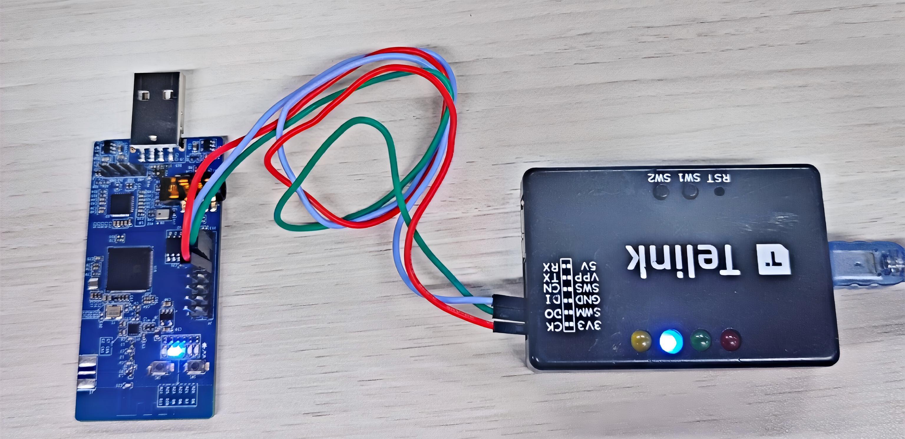
Before using BDT, connect the PC, programmer, and target board as follows:
- PC ↔ Programmer: connect using a USB cable. If the green LED on the programmer is solid on, the programmer has been successfully recognized by the PC.
-
Programmer ↔ Target board: connect using Dupont wires:
- Power lines: VCC ↔ VCC; GND ↔ GND
- Data line (single-wire SWM bus): connect the SWM pin on the programmer to the SWS pin on the target board.
A.3 BDT flashing procedure
This section describes the standard firmware flashing procedure using the Programmer V3 + BDT. BDT flashing for all verification scenarios follows this procedure.
Step 1: Connect the device
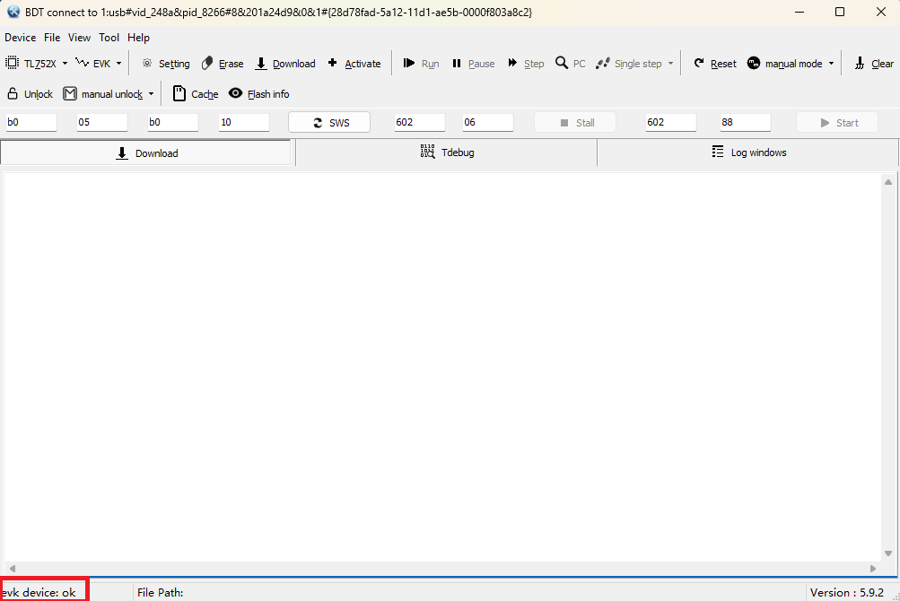
Open the BDT software. Before flashing firmware, ensure the tool has detected the programmer, as shown below.
- If BDT does not find a device, click Refresh to view available devices.
- If BDT discovers multiple devices, all devices are listed. After clicking Refresh, the first device is activated by default; you can also manually switch the target device in the list.
Step 2: Select the target chip
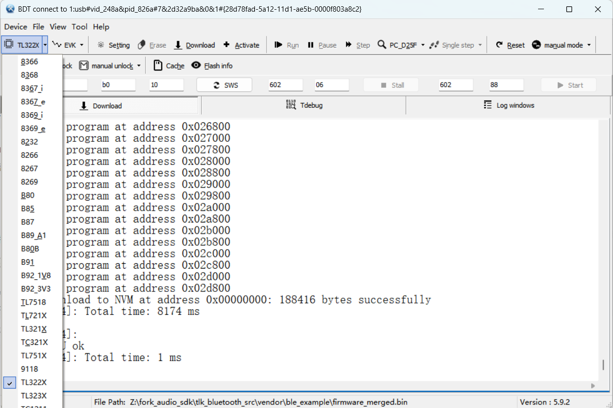
From the chip dropdown menu at the top, select the target chip corresponding to your development board, e.g., TL322x.
Step 3: Select the download mode
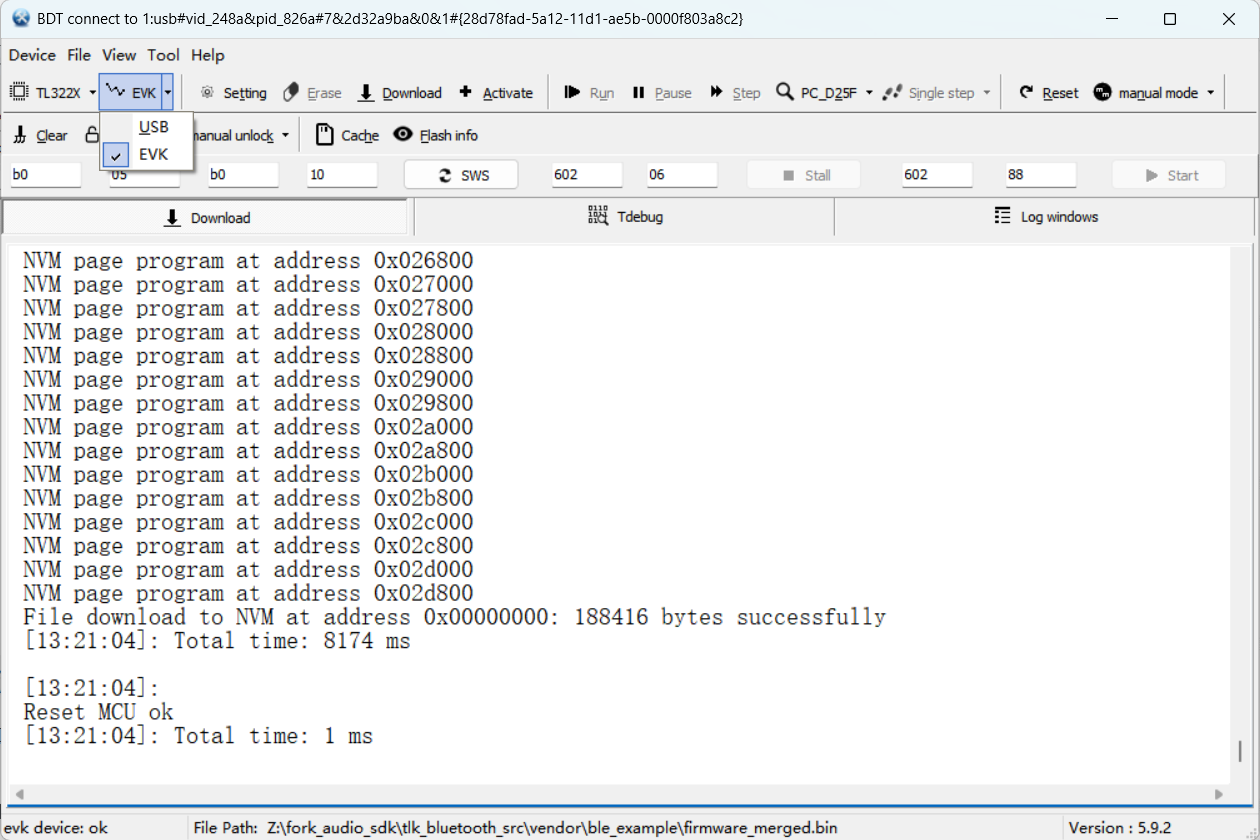
Select EVK as the download mode.
Step 4: Set the flash address
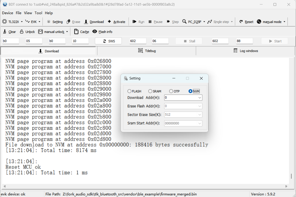
Click the Setting button to open the configuration window and switch to the NVM tab. Set the firmware start offset address in the Download Addr field; the default value is 0x000000.
Notes
Firmware in this scenario is flashed to NVM (not Flash). Simply select the NVM radio button in BDT's Setting dialog. If Flash is mistakenly selected, the old program will still run after download.
Step 5: Load the firmware file
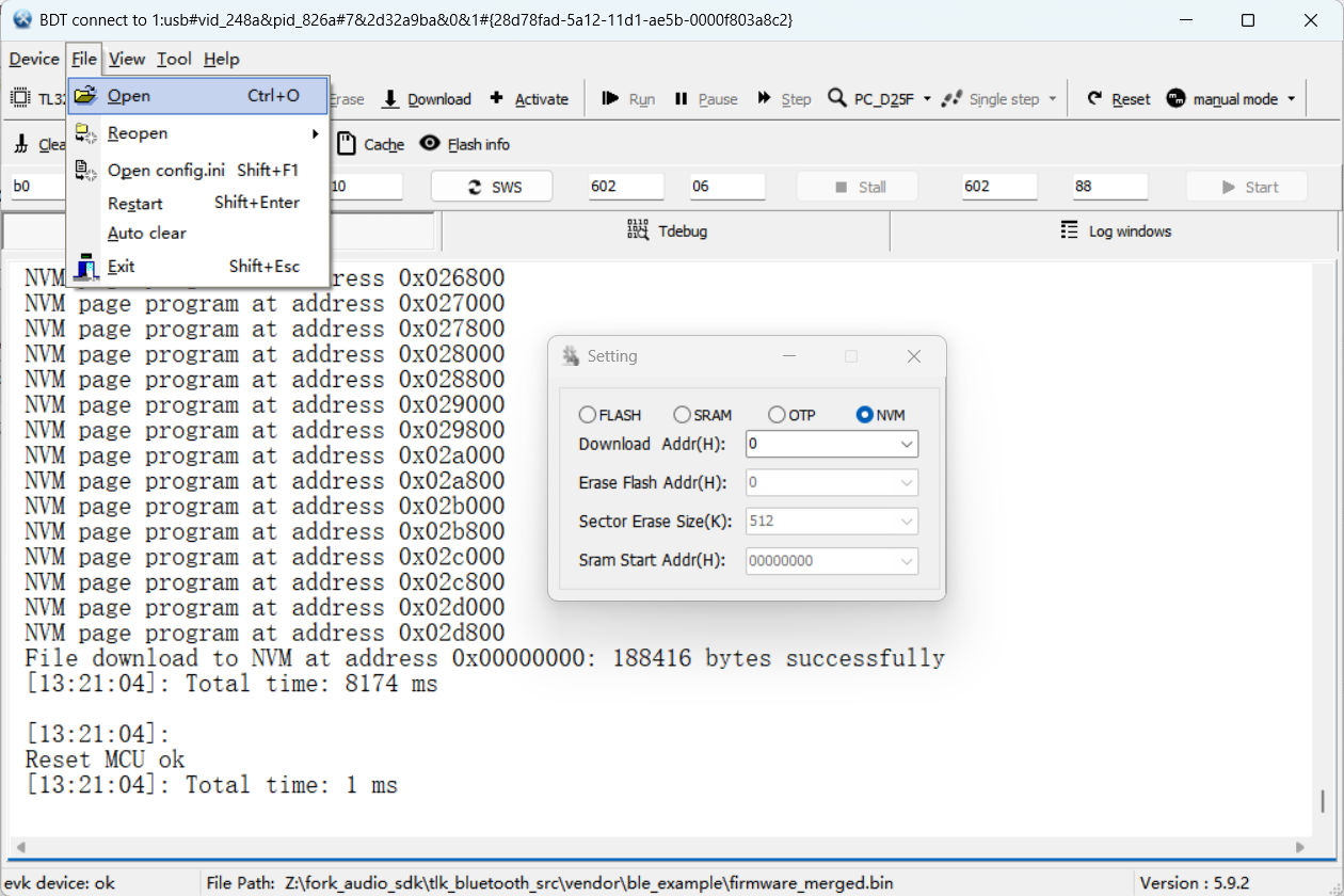
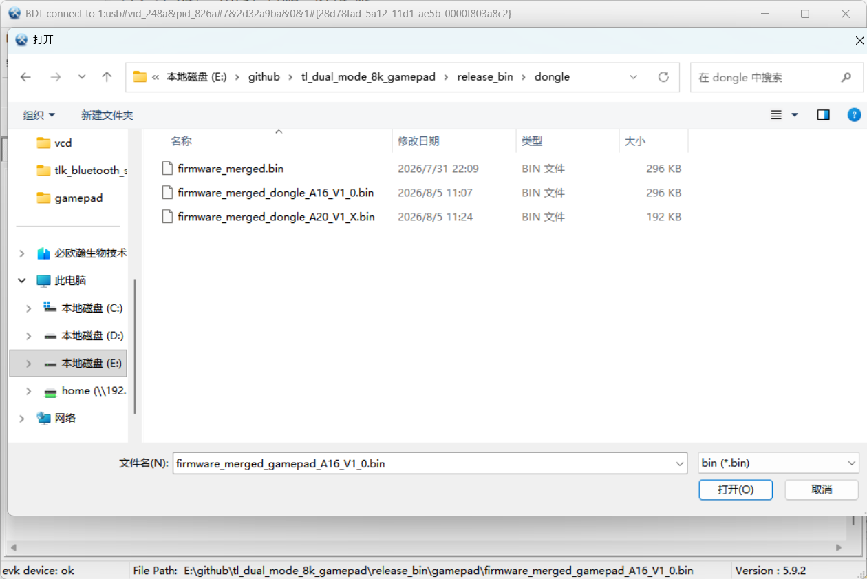
Click File → Open/Reopen in the menu bar and select the corresponding .bin firmware. After successful loading, the full file path is displayed at the bottom of the main interface.
Step 6: Check the connection status
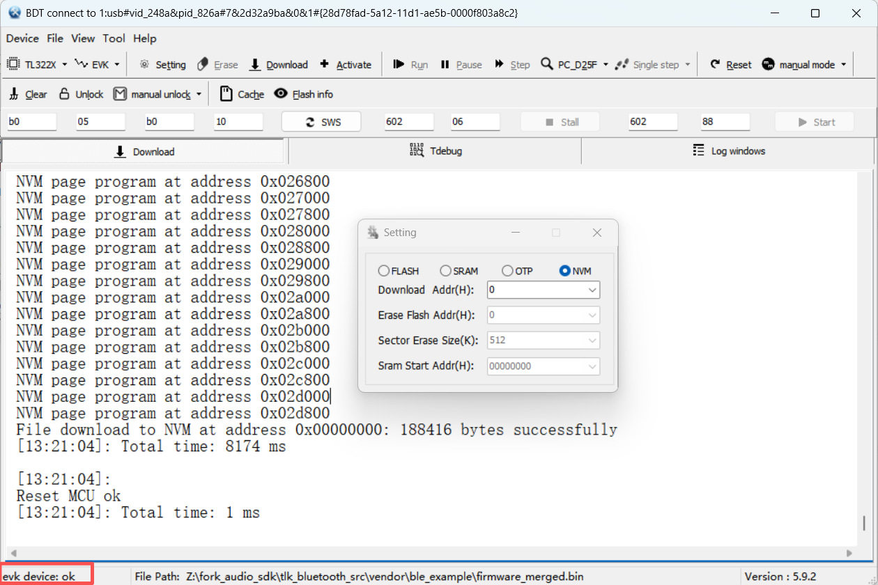
- If the connection status is normal, evk device: ok is displayed in the lower-left corner of the main interface.
- If usb device: not found is displayed in the lower-left corner of the main interface, the target board is not correctly connected to the PC.
Step 7: Unlock NVM write protection
Click the Unlock button or check the auto unlock option to disable NVM write protection.
If NVM is in a write-protected state, Download will fail; therefore, before downloading firmware to NVM, ensure NVM is in a programmable state.
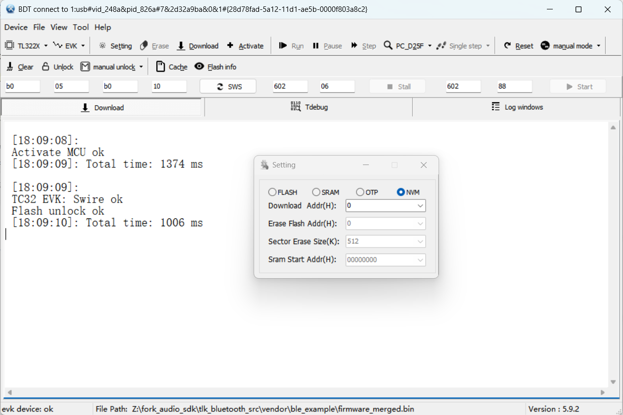
Modify eFuse: this modification is unique and can only be performed once; it is a mandatory step after unlocking NVM write protection and before flashing firmware.
Refer to the screenshot below and switch the option to the eFuse modification position, then complete the modification as follows (if you have confirmed that the chip's eFuse has already been modified, you may skip the modification steps and proceed directly to the modification result verification below).
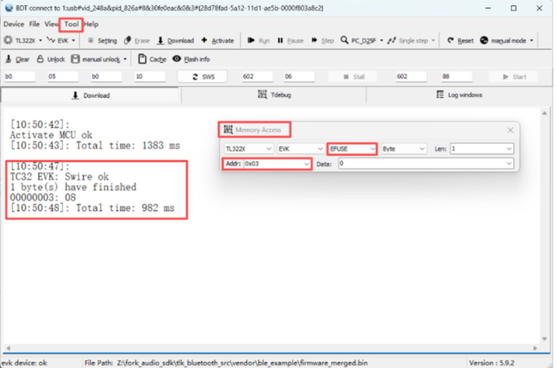
- Enter
0x03in Addr and08in Data, then press Enter and check whether the write succeeds. - Enter
0x9ain Addr and80in Data, then press Enter and check whether the write succeeds. - Enter
0xaein Addr and08in Data, then press Enter and check whether the write succeeds.
After the modification succeeds, the download will succeed. From then on, this chip can only be flashed with RRAM and cannot run flash programs.
Modification result verification:
After the modification is complete, read the values item by item as follows to confirm that the eFuse has been written successfully:
- Enter
0x03in Addr, then press Tab and check whether the read value is08. - Enter
0x9ain Addr, then press Tab and check whether the read value is80. - Enter
0xaein Addr, then press Tab and check whether the read value is08.
Step 8: Flash the firmware
First click Activate to activate the development board, then click the Download button and wait for the log window to indicate flashing success.
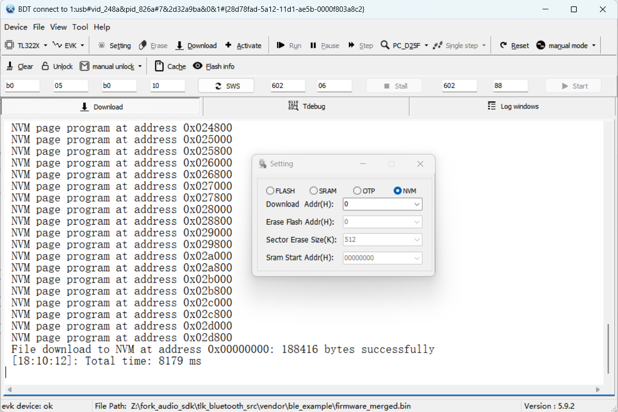
Step 9: Reset and run
You can set the reset mode to auto mode before flashing, or switch to manual mode after flashing and click the Reset button to manually reset the MCU to run the program.
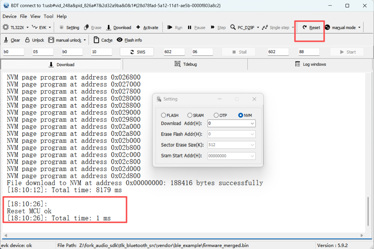
Appendix B: Frequently asked questions
Flashing-related
BDT cannot connect to the device:
- Verify that the correct chip model is selected (TL322x series).
- Check hardware connections (3V3 / GND / SWM–SWS) and confirm that the programmer and development board share a common ground and are properly powered.
- Ensure there is no power conflict on the development board (e.g., if the development board is simultaneously connected to a PC via USB Type-C, disconnect either the 3V3 Dupont wire or the USB cable, keeping only SWS / GND connected).
- Re-plug the programmer or click Device → Refresh in the BDT tool.
Program does not run after flashing:
- Verify that the flash address is correct (
0x000000). - Verify that the storage area is set to NVM (not Flash).
- After flashing, click the Reset button to reset the MCU, or power cycle the device.
USB OTA upgrade fails:
- Confirm that the device has completed first-time flashing. USB OTA is only used for firmware upgrades; the first-time flashing of a factory prototype must be done via BDT.
- Confirm that the
dfu_update.batscript is double-clicked within 5 s after pressing the "reset/upgrade" button (if more than 5 s elapses, the device restarts automatically and you need to repeat the operation). - Confirm that the firmware file name referenced in the upgrade script is consistent with the actual firmware file name to be upgraded.
- Confirm that the Gamepad and Dongle firmware have not been flashed to the wrong device. If they have, re-flash via BDT first, after which USB OTA can be used again.
Functional verification-related
2.4G pairing failure:
- Confirm both devices are powered on and within the 5-second auto-pairing window after power-on (if the window has expired, reset both devices and power cycle to retry).
- Confirm the development boards have antennas installed.
- Confirm the distance between the two boards is within 0.5 m.
- Close applications on the PC that consume CPU/USB resources.
- Reset both devices and retry.
HID does not report data:
- Confirm that the corresponding button on the Gamepad side has been pressed to trigger HID:
- TL322x development kit → press SW4
- TL322x PA Dongle development board → press SW2
- Confirm that the PC has recognized the gamepad device (Device Manager /
joy.cpl). - Check whether the Gamepad side and Dongle side have been successfully paired (LED status on the boards).
Report rate cannot reach 8 kHz:
- Confirm that the HID Only configuration is in use. In HID + BLE mode the report rate is approx. 7.7–7.8 kHz; in HID + Audio + BLE mode it is approx. 900 Hz.
- During testing, close other applications on the PC to avoid CPU resource contention.
- Check whether the power supply is stable (low voltage may cause RF power degradation).
BLE device cannot be discovered:
- Try resetting the Gamepad side and re-scanning with nRF Connect.
No audio output:
- Confirm the Dongle side is connected to the PC via USB.
- Confirm the 3.5mm headphones are plugged into the headphone jack on the Gamepad side (not the PC audio jack).
- Check whether the Dongle-side audio output device is selected in the PC sound settings.
- Confirm the Gamepad side and Dongle side have been successfully paired.
Community and resources
| Resource | Description |
|---|---|
| Telink official forum | Technical discussion and support |
| Telink official website | Product center |
| Telink documentation website | Documentation center |