Telink Capacitive Touch Button Getting Started
Overview
The capacitive touch button (CTB) detects the capacitance change caused by a finger touch to determine whether the button is pressed. It can be used in button-related scenarios, such as home appliance control panels, light switches, touch panels, and other smart home interactive components.
This document is the demonstration guide for the CTB module. The demo verifies the basic CTB functions from two perspectives: button channel quantity (no channel, 8 channels, and 16 channels) and button sensitivity (high sensitivity and low sensitivity). It helps you quickly understand how CTB works and verify the CTB_Demo.
Hardware and software preparation
Hardware checklist
| Hardware type | Model/specification | Quantity | Description |
|---|---|---|---|
| PC | Windows 10/11 / Linux / MacOS | 1 | Development host used to run the flashing software. This document uses a Windows 11 PC as an example. |
| Development board | TL3228XDK96D C1T371A20 | 1 | Development board with capacitive buttons, equipped with a TL322x series chip. |
| Programmer | Telink programmer | 1 | Used to flash firmware to the target chip. |
| Connection cable | USB Type-C cable | 2 | One connects the PC and the programmer for firmware flashing. One connects the PC and the development board for log output. |
| Dupont wires | 3 | Connect the development board and the programmer. |
Note
TL3228XDK96D C1T371A20 is a customized development board for specific application scenarios. If you are interested in this demonstration, please contact us.
Software checklist
| Software/firmware | Name | Description |
|---|---|---|
| Flashing tool | BDT (Burning and Debugging Tool) | Dedicated flashing software used to flash firmware to the development board. |
| Precompiled firmware | CTB_Demo_V1.0.0.bin | Firmware for CTB function verification. |
| Test tool | UART debug assistant | Serial communication debugging tool for Windows. |
Installing BDT
Telink Burning and Debugging Tool (BDT) is used to flash firmware to the target development board.
The BDT installation steps:
-
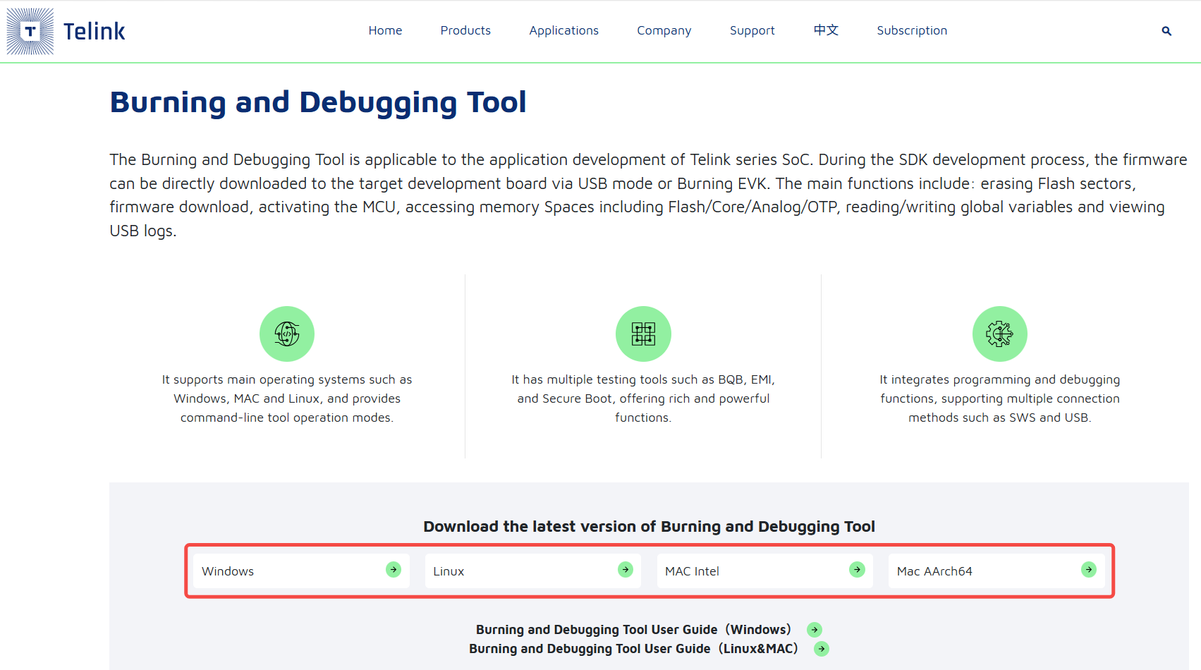
Download BDT. Go to Telink Developer Center - Development Tools and download the package for your operating system.
-
Extract the package.
BDT is portable and requires no installation. Unzip it to use.
Example for Windows:
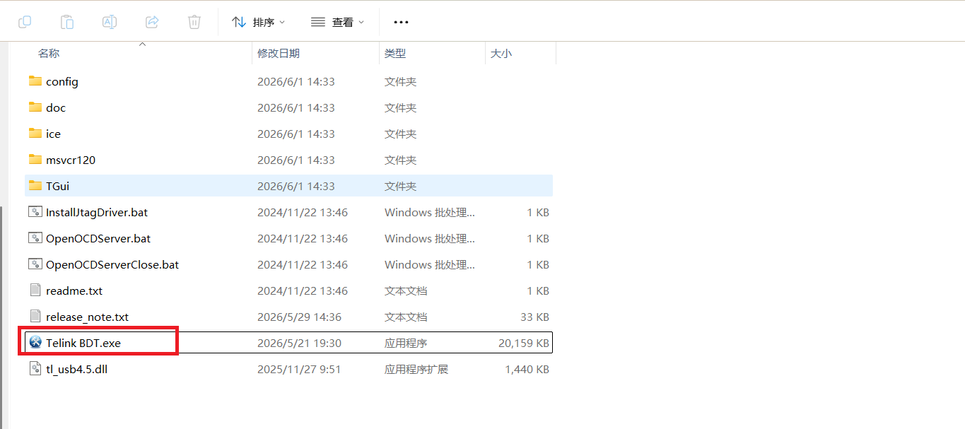
- Extract the downloaded package to a path of your choice, for example, C:\Telink\BDT.
- Go to the release directory, for example, C:\Telink\BDT\release_v5.9.6.
- Double-click Telink BDT.exe to start the tool.
-
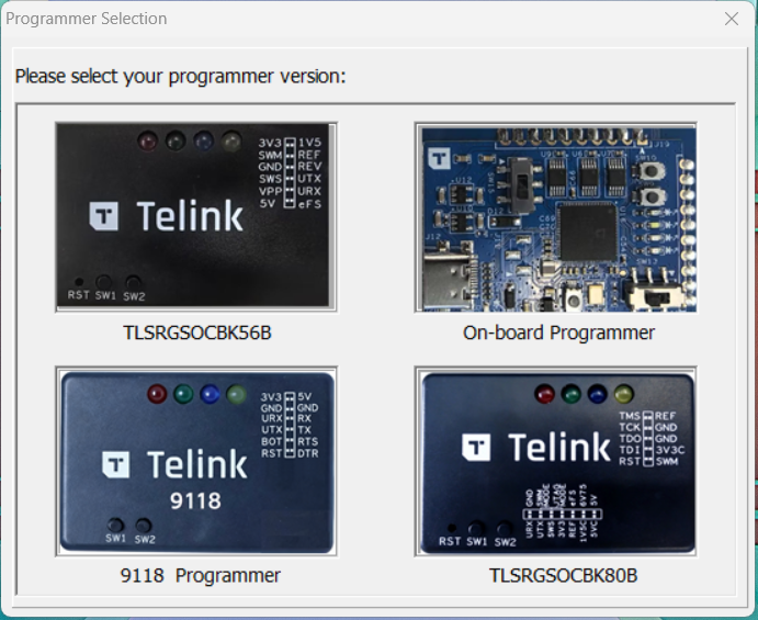
Select the programmer version. The BDT supports multiple programmer versions; select the one that matches your chip series. This document uses Programmer TLSRGSOCBK56B as an example.
Hardware connection
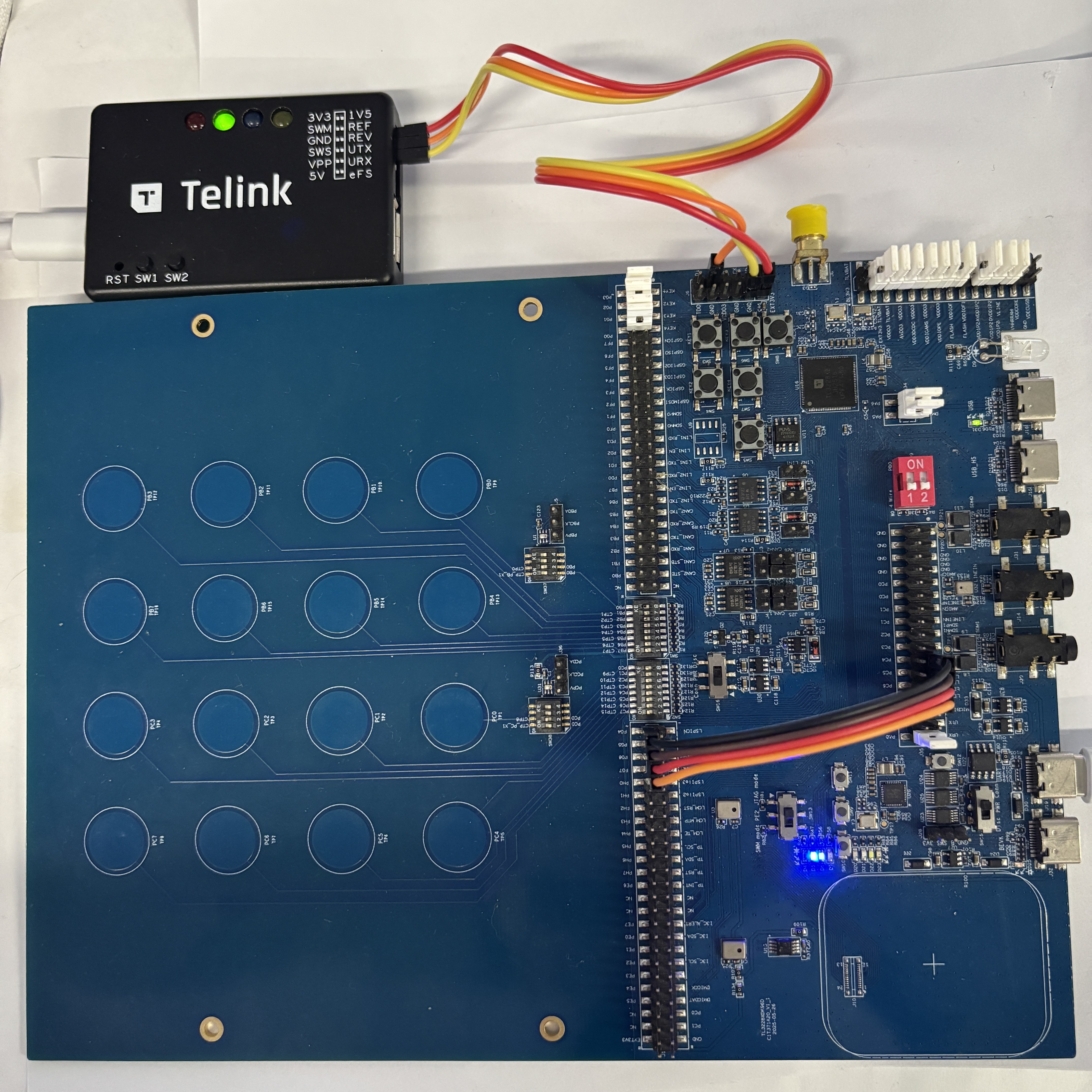
The hardware connection diagram of the development board is shown below:

Use three Dupont wires to connect the programmer and the development board, as listed below.
| No. | Programmer | Development board |
|---|---|---|
| 1 | 3V3 | J6.EXT3V3 |
| 2 | GND | J6.GND |
| 3 | SWM | J6.SWS |
The LED jumper wire connections are as follows:
| No. | J1 | J35 |
|---|---|---|
| 1 | PG4 | LEDR |
| 2 | PG5 | LEDB |
| 3 | PG6 | LEDW |
| 4 | PG7 | LEDG |
The DIP switch settings are as follows:
| No. | Switch silkscreen | DIP direction |
|---|---|---|
| 1 | SW1 | All 8 switches to PBx |
| 2 | SW2 | All 8 switches to PCx |
| 3 | SW37 | Switch 2 to CTP, switch 1/3/4 to PB |
| 4 | SW38 | Switch 2 to CTP, switch 1/3/4 to PC |
Flashing firmware
Use BDT to flash the precompiled file CTB_Demo_V1.0.0.bin to the chip on the development board. The steps are as follows.
-
Check whether BDT has detected the programmer.
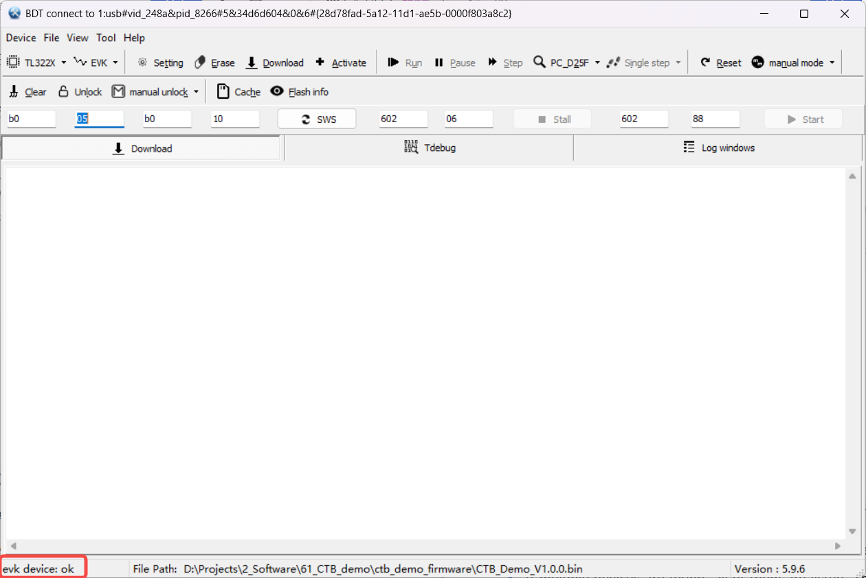
- If no device is found, click Device > Refresh to refresh the device list.
- If multiple devices are found, all of them are listed. The first device is activated by default, and you can switch the target device manually in the list.
-
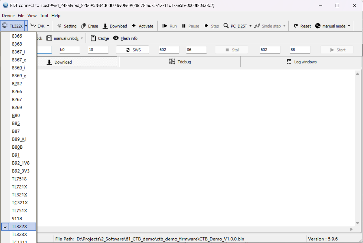
Select the chip series TL322X for the TL3228X development board.
-
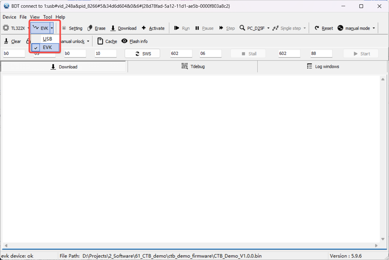
Select EVK as the download mode.
-
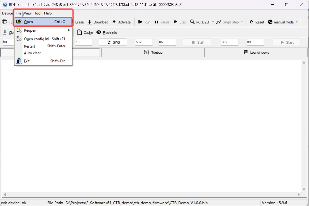
Click File > Open in the menu bar and select the firmware file to flash. After the file is loaded, the full path is shown at the bottom of the main window.
-
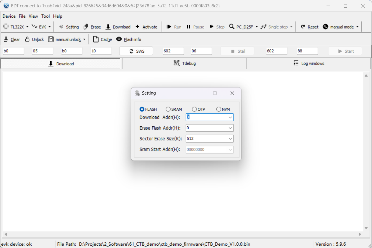
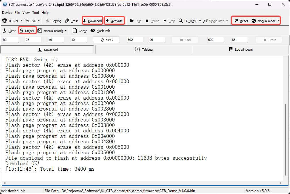
Click Setting to configure Flash:
Download Addr(H): 0Erase Flash Addr(H): 0Sector Erase Size(K): 512
-
Click Unlock to remove Flash write protection. Download fails while Flash is write-protected.
-
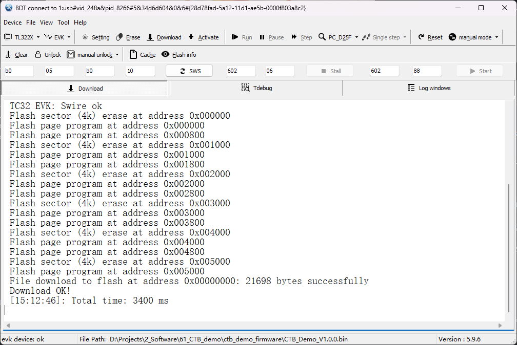
Click Activate to activate the development board, then click Download to flash the selected firmware to the board. Wait until the log window reports success.
-
Reset and run. Set the reset mode to auto mode before flashing; the chip resets and runs automatically after flashing. If manual mode is selected, click Reset after flashing.
After flashing succeeds and the board resets and runs, the blue LED on the development board blinks.
Verification result
This section demonstrates how to flexibly configure multi-channel touch buttons and buttons with different sensitivity levels.
Connect the test tool
Download the UART Debug Assistant, which is free portable software.
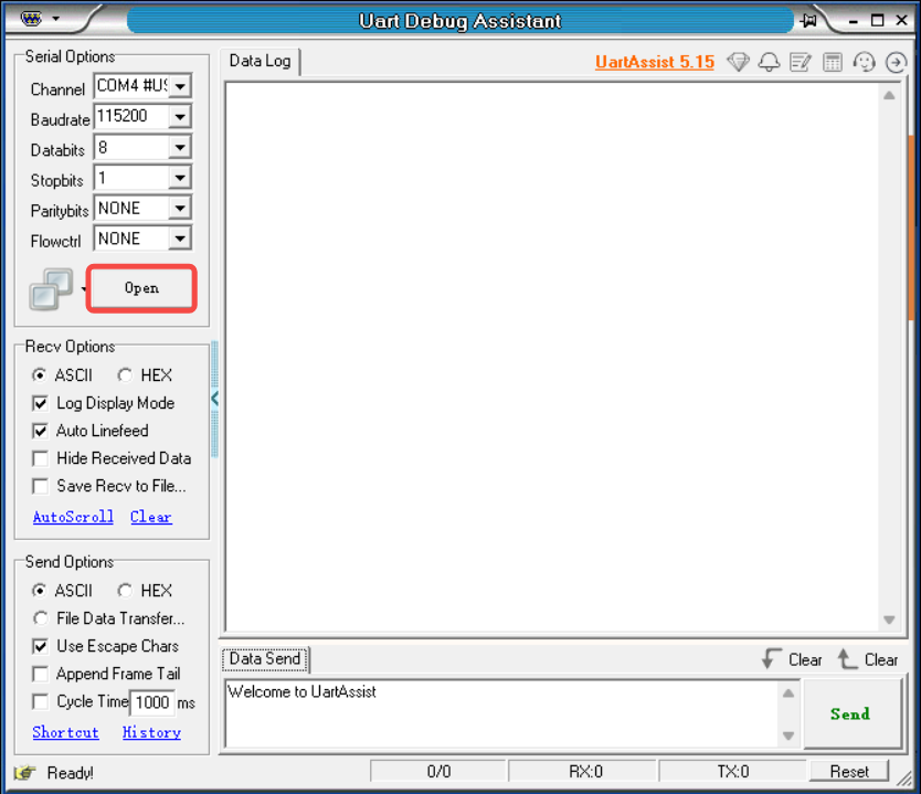
Make sure the USB cable of the log interface is connected to a USB port on the PC. Open the uart debug assistant, select the USB port as the channel, and click Open to connect the tool to the log serial port.
Channel verification
No channel
There are two ways to enter no-channel mode:
- After flashing the firmware, no button channel is enabled by default, and the blue LED on the board blinks.
- In another mode (with an LED of another color blinking), press Key1 to switch to no-channel mode, and the board starts blinking blue.
In no-channel mode, pressing any of the 16 capacitive buttons shows no data logs in the uart debug assistant.
16 channels
In another mode (with an LED of another color blinking), press Key3 to switch to 16-channel (all-channel) mode, and the board starts blinking white, as shown below.
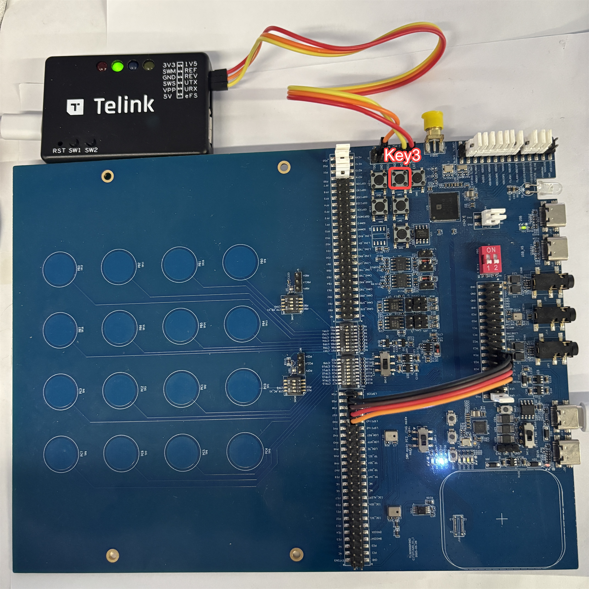
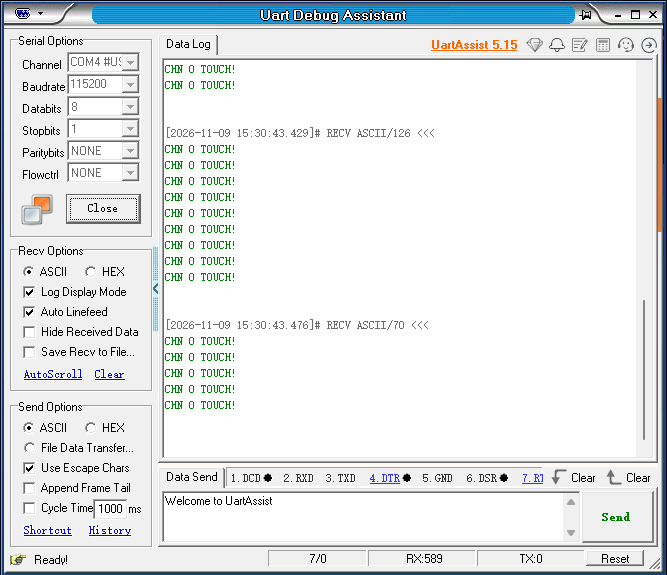
In 16-channel mode, pressing any of the 16 capacitive buttons prints the corresponding channel information. Press only one button at a time. The red LED on the board lights up, and the channel information is printed in the data log window while the button is pressed (the figure below shows channel 0 for TP1). After you release the button, printing stops and the red LED turns off after 0.5 s.
8 channels
In no-channel or 16-channel mode, press Key2 to switch to 8-channel mode, and the board starts blinking green, as shown below.
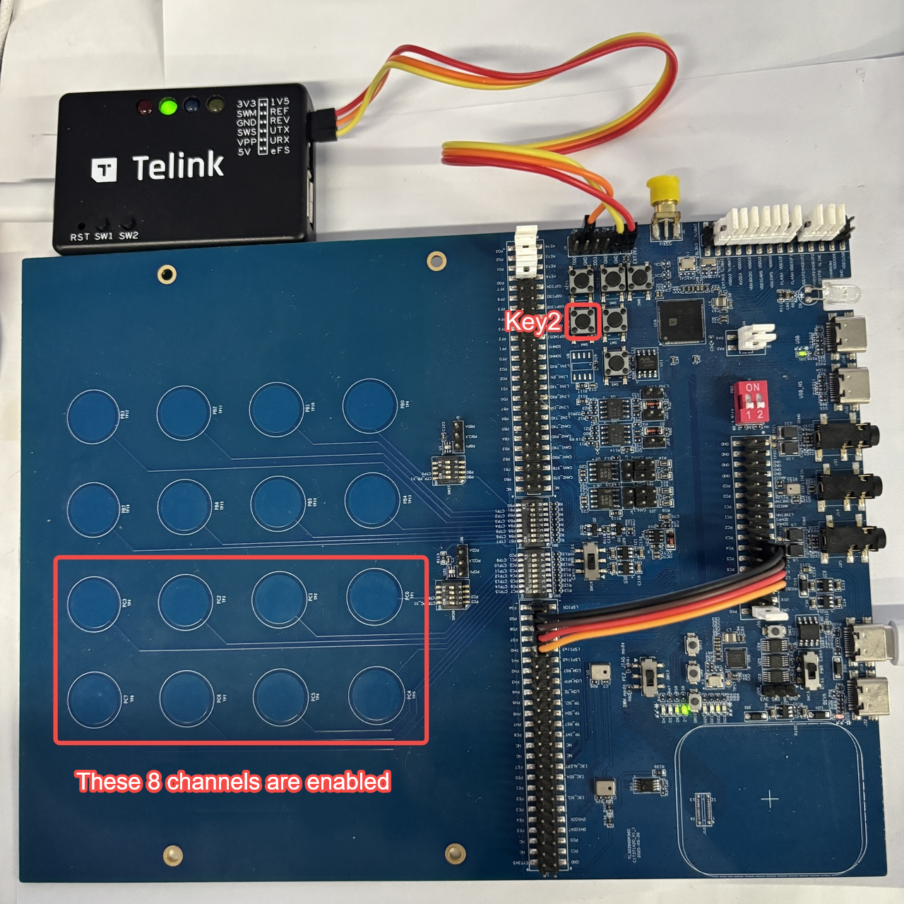
In 8-channel mode, press the lower eight of the 16 capacitive buttons (TP1 to TP8), one at a time. The red LED lights up, and the corresponding channel information is printed in the data log window while the button is pressed. Pressing the upper eight buttons (TP9 to TP16) turns on no red LED, and no channel information is printed. This mode also supports sensitivity verification, as described in Sensitivity verification.
Sensitivity verification
In 8-channel mode, you can verify the CTB sensitivity. Two levels are available: high sensitivity and low sensitivity, distinguished by a short press and a long press. For more sensitivity settings, please contact us.
High sensitivity
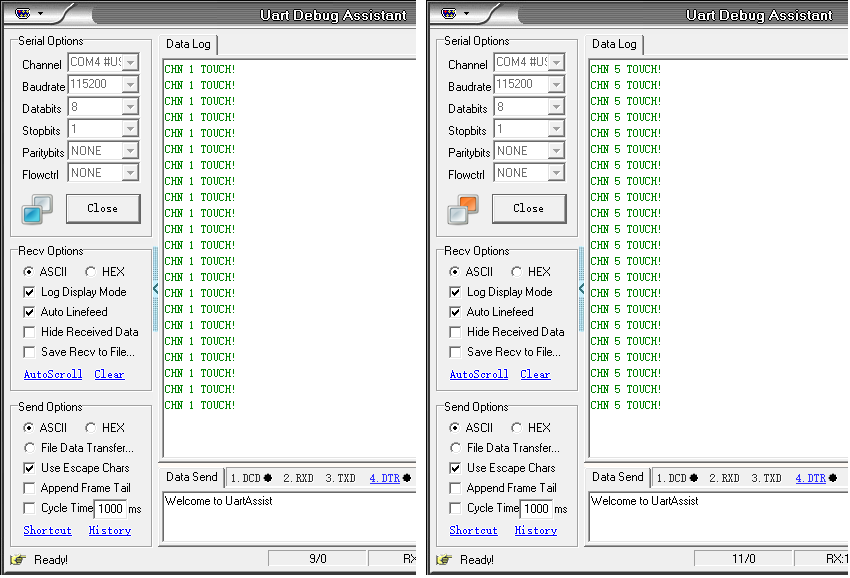
TP1, TP2, TP5, and TP6 (channels 0, 1, 4, and 5) are high-sensitivity buttons. Short-press these buttons to see the red LED light up and the channel information in the uart debug assistant. The figure below shows the output for channels 1 and 5.
Low sensitivity
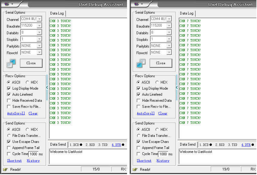
TP3, TP4, TP7, and TP8 (channels 2, 3, 6, and 7) are low-sensitivity buttons. A short press produces no response on the board or in the uart debug assistant. Long-press these buttons to see the red LED light up and the channel information in the uart debug assistant. The figure below shows the output for channels 3 and 7.
FAQ
CTB channel to GPIO mapping
- The GPIO pin of each CTB channel is fixed. See the chip datasheet, or the
ctb_in_pinsarray in thectb.cfile in the SDK. - GPIO pins of enabled CTB channels should not be used for other purposes. For example, the demo uses PG4 to PG7 as LED pins, which correspond to CTB channels 4 to 7; if they are used for CTB, do not use them for LEDs.
UART debug assistant fails to open
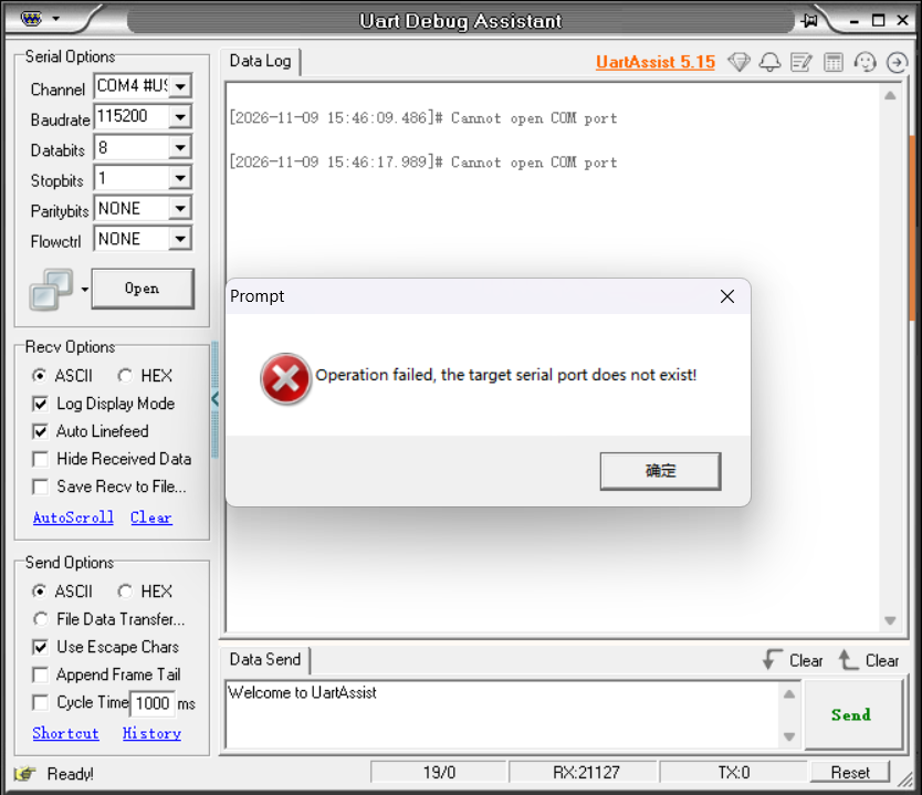
If a prompt indicates that the serial port assistant fails to open, unplug the USB cable for serial debugging and plug it back into the PC. Select the newly added port for the channel selection, and then click Open.
Do I need to flash the firmware again after the board is powered off?
A: No. After the power and ground lines of the development board are connected and the board is powered on, click Reset in BDT to reset and run; the blue LED on the board starts blinking.
Community and resources
| Resource | Description |
|---|---|
| Telink official forum | Technical communication and support |
| Telink official website | Product center |
| Telink documentation website | Documentation center |