telink_9118_wifi_sdk Get Started
Overview
About this document
This document is to help you quickly set up the telink_9118_wifi_sdk development environment, obtain the SDK, build and flash the project, and run the first example application.
Applicable scope
telink_9118_wifi_sdk is applicable to Telink's TLSR9118 SoC platform.
Info
- For information about supported chip models, corresponding development boards, and SDK versions, refer to the official website.
Preparation
Hardware checklist
| Hardware | Description |
|---|---|
| PC | Windows 10/11 or Ubuntu 20.04 or later (64-bit Linux recommended) |
| Development board | TLSR9118 development board |
| USB cable | USB Type-C cable |
For physical hardware, refer to Step 1: Connect the hardware.
Software checklist
| Software | Description |
|---|---|
| Development environment | Telink VS Code Extension (Windows/Linux) / command line (Linux) |
| Toolchain | TL32 ELF MCULIB V5 GCC 10.3 |
| Flashing tool | BDT (Burning and Debugging Tool) |
| Python dependencies | pycryptodome/imgtool |
| Serial port tool | Recommended: Tera Term (Windows) / Minicom (Linux) |
| SDK | Gitee/GitHub |
Choose the development environment
The development environments supported by each operating system are as follows:
| Operating system | Telink VS Code Extension | Command line |
|---|---|---|
| Windows 10/11 | ✓ | — |
| Linux | ✓ | ✓ |
Select a development method according to the development requirements.
Prerequisite: Ensure that the latest version of VS Code is installed. An outdated VS Code version may cause the Telink VS Code Extension to malfunction or certain functions to work abnormally.
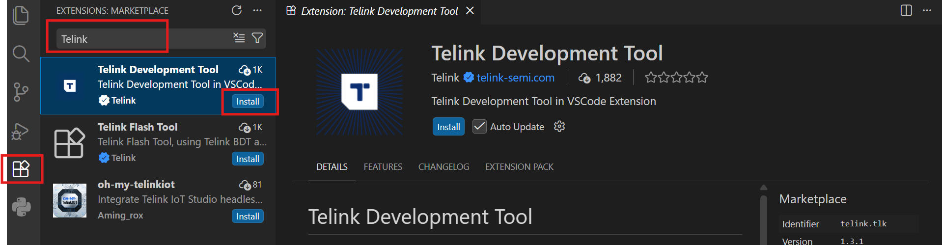
Follow the steps below to install the Telink VS Code Extension:
1. Launch VS Code.
2. Click the Extensions icon in the Activity Bar on the left, or press Ctrl+Shift+X.
3. Enter Telink in the search box.
4. Find Telink Development Tool in the search results and click Install.
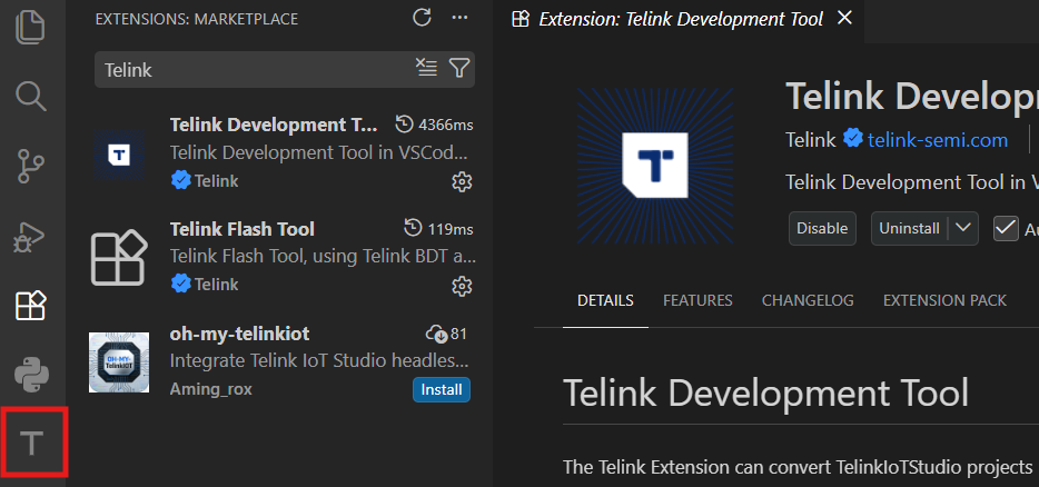
After the installation is complete, the T icon appears in the Activity Bar on the left side of VS Code.
The command-line environment does not require an IDE. However, the following system dependencies must be installed first (Ubuntu is used as an example).
sudo apt update
sudo apt install build-essential libncurses-dev
sudo apt install libevent-dev libnl-3-dev libnl-genl-3-dev
Verify that the system packages have been installed successfully:
dpkg -l | grep -E "build-essential|libncurses-dev|libevent-dev|libnl-3-dev|libnl-genl-3-dev"
The status of all packages should be ii, indicating that they are installed.

Get the SDK and configure the development environment
Download the SDK
Click the Gitee or GitHub link to download the latest SDK version and extract it to the local directory.
SDK directory overview
After extracting the SDK, enter the wits-sdk directory. The wits-sdk directory is the SDK root directory. Its top-level directory contains the following subdirectories.
| Directory | Description |
|---|---|
| api | Telink Wi-Fi APIs |
| app | Example applications |
| configs | Default configurations |
| hal | Hardware abstraction layer |
| include | Header files to be included |
| kernel | Kernel with FreeRTOS and FreeBSD |
| lib | Library modules that may be used |
| prebuilt | Libraries built with predefined configurations |
| scripts | Build-related scripts |
For the complete directory structure and the responsibilities of each directory, refer to the Developer Handbook.
Import the SDK
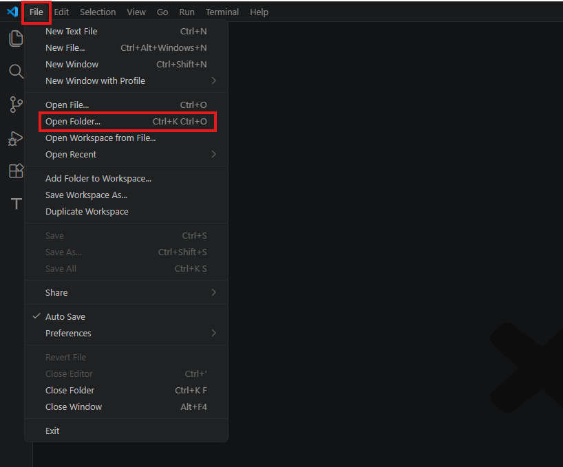
In VS Code, click File -> Open Folder... in the upper-left corner, navigate to the extracted SDK directory, then select the wits-sdk folder and import it.
The SDK does not need to be imported in the command line environment.
Configure the development environment
Download the toolchain
1. Click the T icon in the Activity Bar on the left side of VS Code to expand the WIFI DEVELOPMENT tree.
2. Under the Tools and Settings list, select the TL32 ELF MCULIB V5 GCC 10.3 toolchain and click the install button on the right side of the toolchain, then wait for the installation to complete.
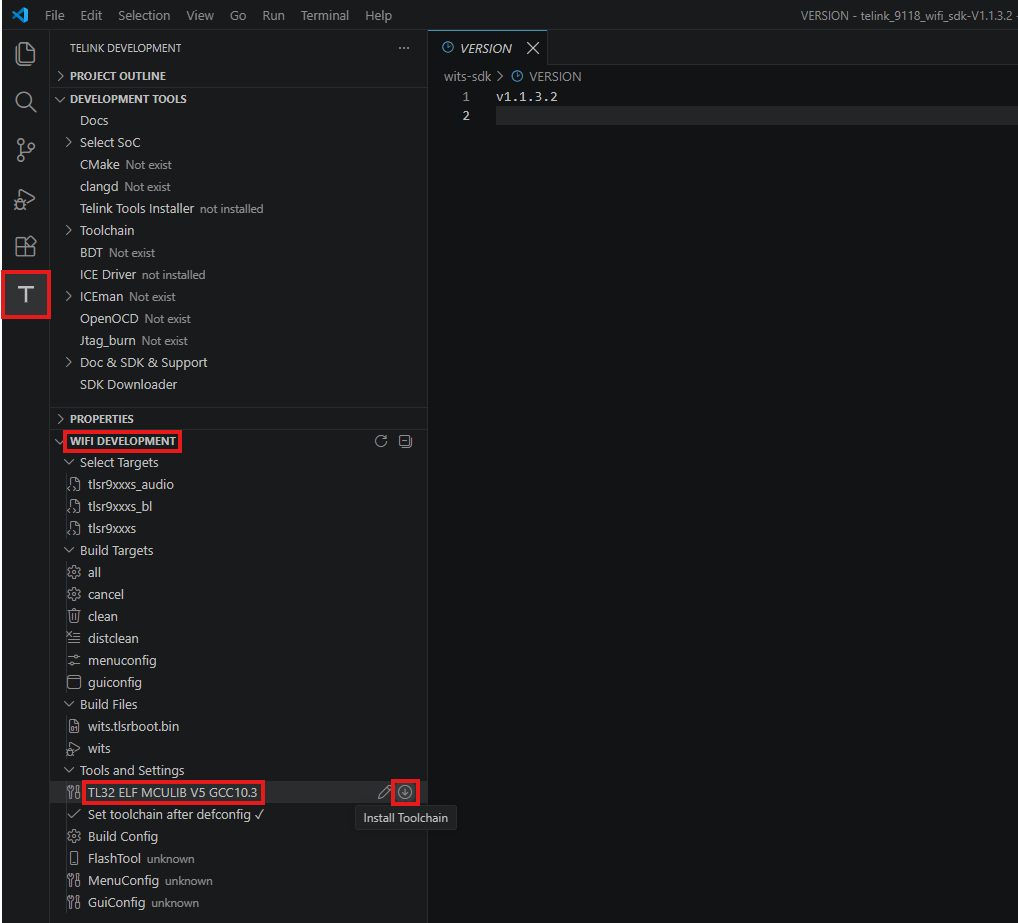
After the installation is complete, a notification indicating successful installation appears in the lower-right corner of the VS Code window.

1. In the terminal, use the following commands to download and extract the toolchain package to the /opt/ directory:
# Switch to the download directory (replace Downloads with your actual download path)
cd ~/Downloads

# Download the toolchain package
wget https://doc.telink-semi.cn/tools/vsc/linux/toolchains/V511_Linux.tar.xz

# Extract the package to /opt/ (sudo privileges are required)
sudo tar -xvJf ./V511_Linux.tar.xz -C /opt/ --strip-components=2
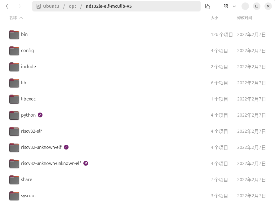
By default, the SDK assumes the toolchain path is /opt/nds32le-elf-mculib-v5/bin/. If you extract it to another directory, run make menuconfig before building and enter the Target platform -> NDSV5 architecture menu to modify the cross toolchain path.
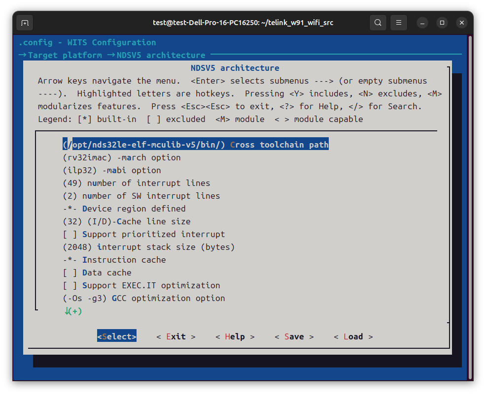
2. In the terminal, enter the following command to verify whether the toolchain is installed successfully:
/opt/nds32le-elf-mculib-v5/bin/riscv32-elf-gcc --version
The version information should be printed normally without the "command not found" error.

Install Python dependencies
During the build, some scripts depend on the Python environment. Follow the steps below to install the required components:
1. Click the T icon in the Activity Bar on the left side of VS Code to expand the WIFI DEVELOPMENT tree.
2. Under the Tools and Settings list, click Python Environment for WiFi SDK, then wait for the installation to complete.
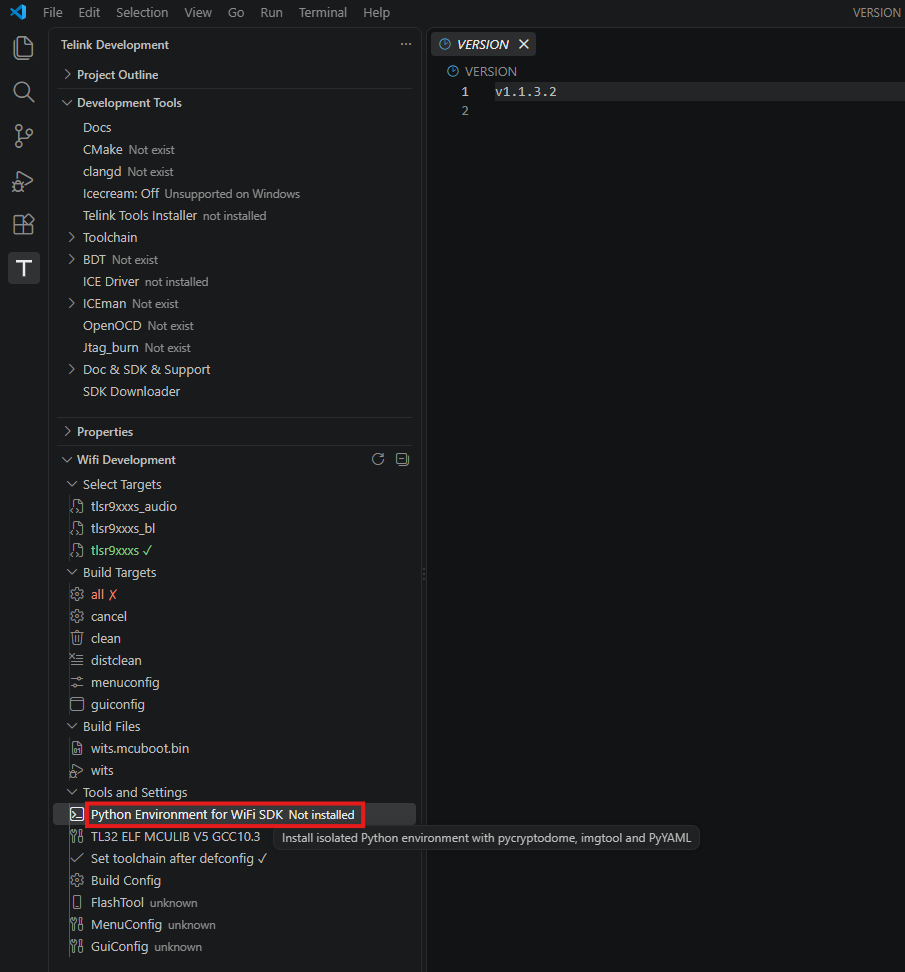
After the installation is complete, a notification indicating successful installation appears in the lower-right corner of the VS Code window.

1. During the build, some scripts depend on the Python environment. Follow the steps below to install the required components:
sudo apt install python3-pip
pip install pycryptodome
pip install imgtool
Note
- Since Ubuntu 23.04, the PEP 668 (externally-managed-environment) mechanism is enabled by default. Running
pip installdirectly in the system Python environment may result in theerror: externally-managed-environmenterror. In this case, append the--break-system-packagesoption to thepip installcommand, for example:
pip install --break-system-packages pycryptodome
pip install --break-system-packages imgtool
- If your system version is earlier than 23.04 (such as Ubuntu 20.04/22.04), this option is not required; run the commands directly.
2. In the terminal, enter the following command to verify whether the Python dependencies are installed successfully:
pip list | grep -E "pycryptodome|imgtool"
The installed pycryptodome and imgtool packages and their version numbers should be displayed.

3. Since these packages are usually installed in the ~/.local/bin directory, add this path to the PATH environment variable. The specific steps are as follows:
(1) Open and edit the ~/.bashrc file:
nano ~/.bashrc
(2) Add the following content to the end of the file:
export PATH=$PATH:~/.local/bin
Save the file and exit nano (press Ctrl+O, press Enter to confirm, then press Ctrl+X to exit)
(3) Run the following command to make the configuration take effect:
source ~/.bashrc
(4) Verify whether PATH already contains ~/.local/bin:
echo $PATH
(5) Verify the PATH configuration:
which imgtool
The full path /home/username/.local/bin/imgtool should be returned.

Build and flash the first example
This section guides you through the complete development process, from selecting an example and building the application to flashing and running the application.
Select the example
It is recommended to choose the Command-line demo as the first example to run. This example is located in the app/cli/ directory. After startup, it prints Hello world! and enters the command line interface, providing a simple way to verify that the development environment has been set up successfully.
The Command-line demo is enabled in the default configuration file tlsr9xxxs_defconfig (CONFIG_DEMO_CMDLINE=y) and requires no additional configuration.
Build the first example
Info
When flashing for the first time or when the Flash is erased, you need to flash both the bootloader and the main firmware:
- wits.tlsrboot.bin
- wits.mcuboot.bin
When the bootloader and Flash layout remain unchanged, and only the application is modified, you only need to rebuild and flash the main firmware:
- wits.mcuboot.bin
1. After importing the SDK in VS Code (see Import the SDK), click the T icon in the left sidebar to enter the WIFI DEVELOPMENT section.
2. Click the corresponding buttons in the following order to build.
(1) Build the bootloader:
a. Click the distclean button under Build Targets to clean up residual files.
b. Select the tlsr9xxxs_bl configuration under Select Targets.
c. Click the all button under Build Targets to start building.
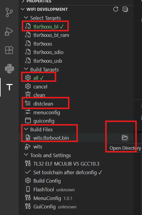
After the build is complete, the generated wits.tlsrboot.bin file is available under Build Files. Click the folder icon on the right side of the file and back up the file to any other directory.
(2) Build the main firmware (Command-line demo):
a. Click the distclean button to clean up residual files in preparation for the build.
b. Select the tlsr9xxxs configuration under Select Targets.
c. (Optional) If you need to adjust the default configuration, click the menuconfig button under Build Targets to open the configuration interface. For detailed steps, refer to Appendix 2: Download the Telink VS Code Extension auxiliary tools.
d. Click the all button under Build Targets to start building.
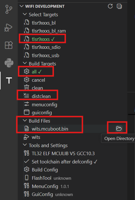
After the build is complete, the generated wits.mcuboot.bin file is available under Build Files. Click the folder icon on the right side of the file and back up the file to any other directory.
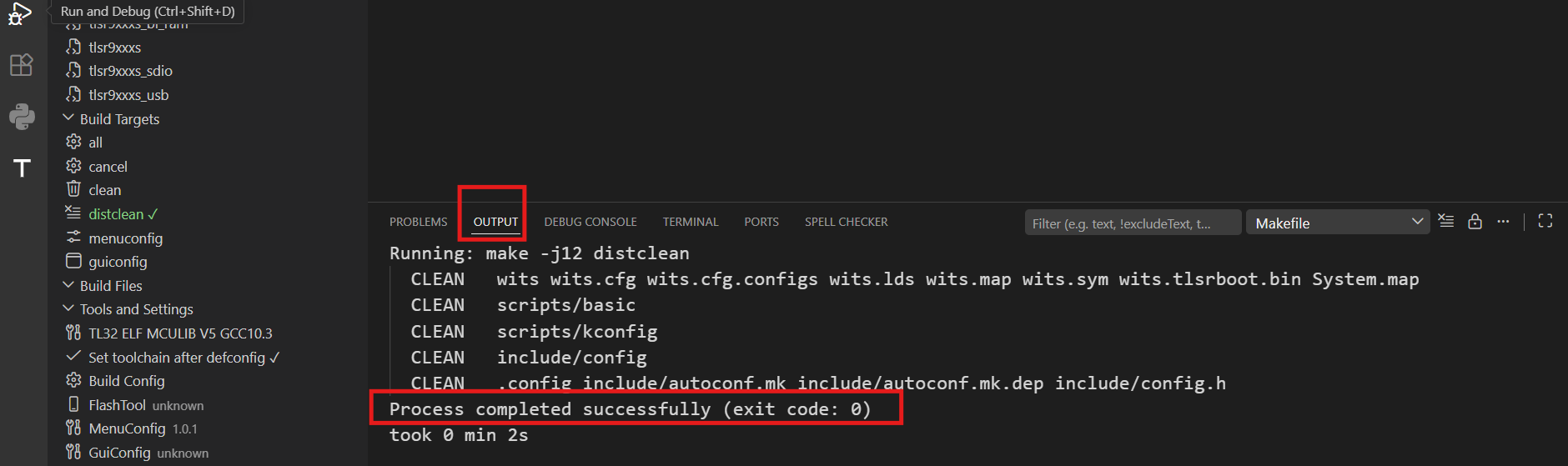
When following the steps above, the OUTPUT area outputs log information in real time. When Process completed successfully (exit code: 0) appears, it indicates the step has been completed successfully.
1. Build the bootloader:
# Enter the SDK root directory. Replace the path with the actual SDK path.
cd path/to/telink_9118_wifi_sdk/wits-sdk/

# Clean up residual files from the last build
make distclean

# Select the bootloader configuration
make tlsr9xxxs_bl_defconfig

# Start building (enable multi-core parallel compilation)
make -j$(nproc)
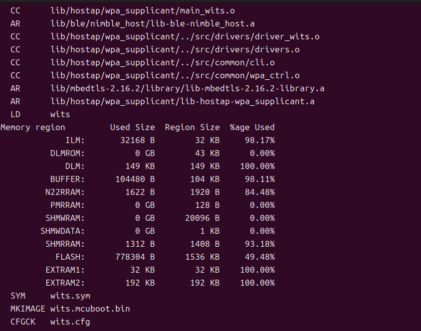
After the build is complete, wits.tlsrboot.bin (bootloader image) is generated in the SDK root directory. Because the make distclean commands remove previously built firmware, back up the firmware to another directory promptly after the build is complete.
2. Build the main firmware (Command-line demo):
# Clean up residual files from the last build
make distclean

# Select the default configuration (the Command-line demo is enabled by default)
make tlsr9xxxs_defconfig

# (Optional) Run menuconfig if you need to adjust the configuration
make menuconfig

# Start building (enable multi-core parallel compilation)
make -j$(nproc)
After the build is complete, wits.mcuboot.bin (main firmware image containing the MCUboot header) is generated in the SDK root directory. Back up the firmware promptly.
Flash the firmware
Step 1: Connect the hardware
Connect the PC and the development board as follows:
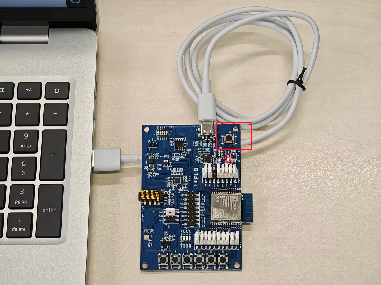
- PC <-> Development board: Connect the PC and development board using a Type-C data cable. If the LED on the development board lights up normally, it indicates the development board is powered on successfully.
Select the tab for your operating system:
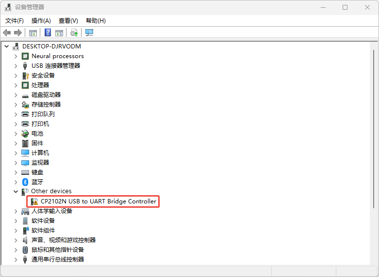
Open the Device Manager on the PC. If the CP2102N USB to UART Bridge Controller appears in the Other devices list as shown in the figure below, it indicates that the PC has successfully connected to the development board.
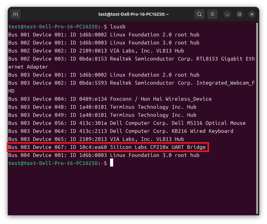
Enter the lsusb command in the terminal.
When the information shown below appears, it indicates the development board has been successfully recognized by the PC.
Step 2: Install the BDT
1. Download the BDT:
Download link: BDT (Windows)
Download link: BDT (Linux)
2. Extract the downloaded package to a custom directory.
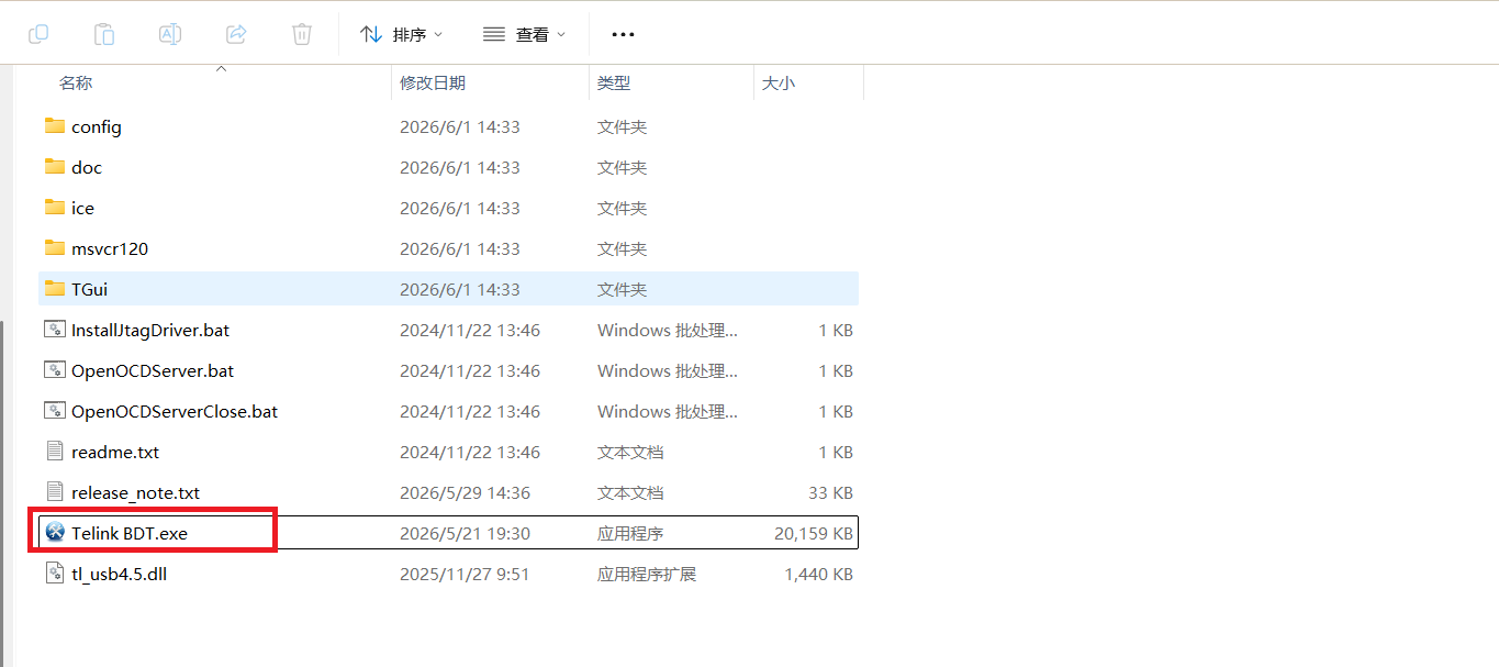
3. Enter the extracted release directory.
Double-click Telink BDT.exe to launch the tool.
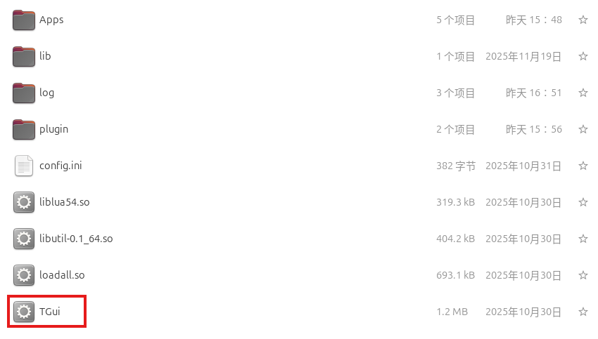
(1) Extract the TGui-BDT-Linux-V1.0.2.tar.gz package and enter the extracted directory.
(2) Double-click the executable file TGui to launch the tool.
Step 3: Flash the firmware
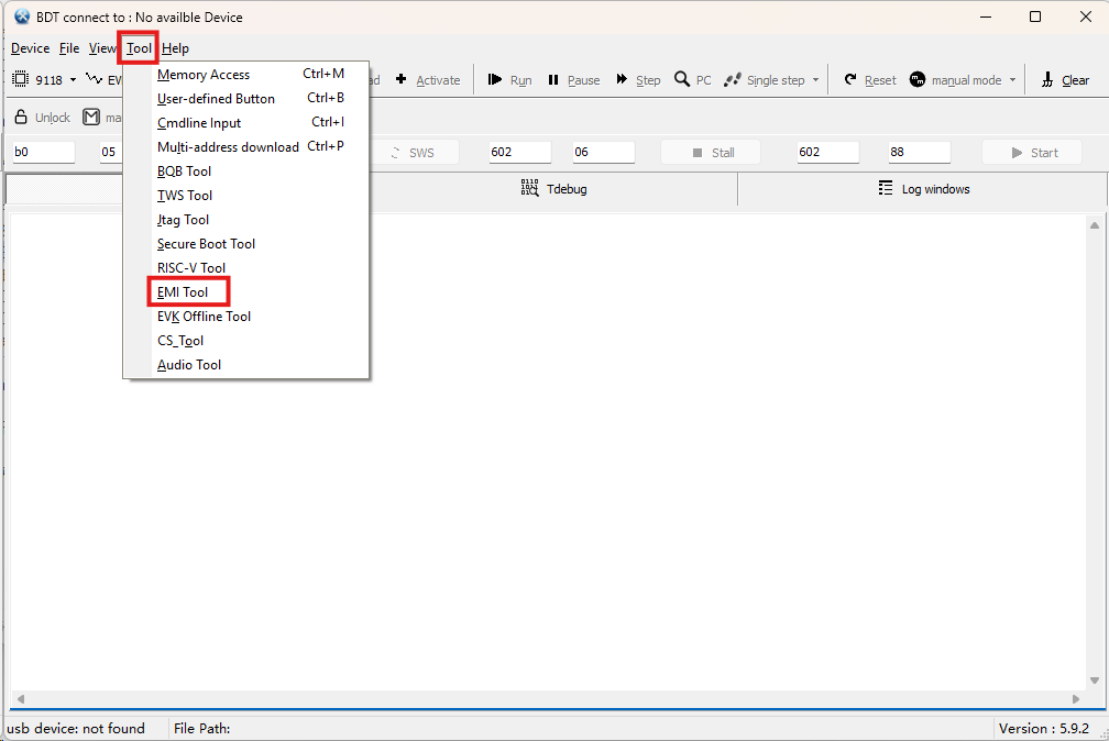
1. Double-click Telink BDT.exe, select 9118 Programmer, and the EMI Tool window opens automatically. The following figure shows the interface:
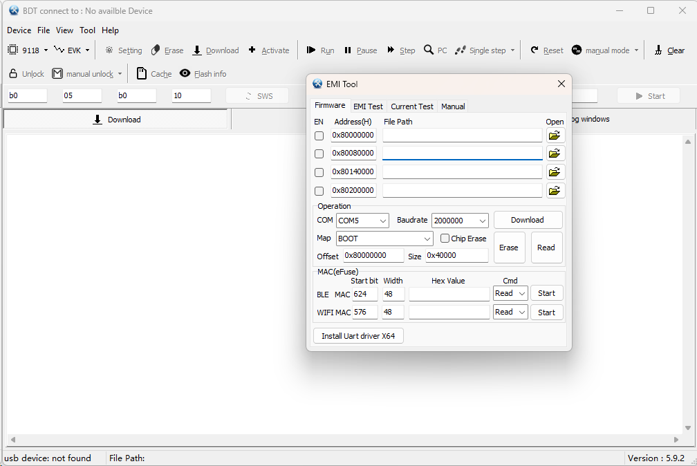
If the EMI Tool does not open automatically, click Tool -> EMI Tool manually.
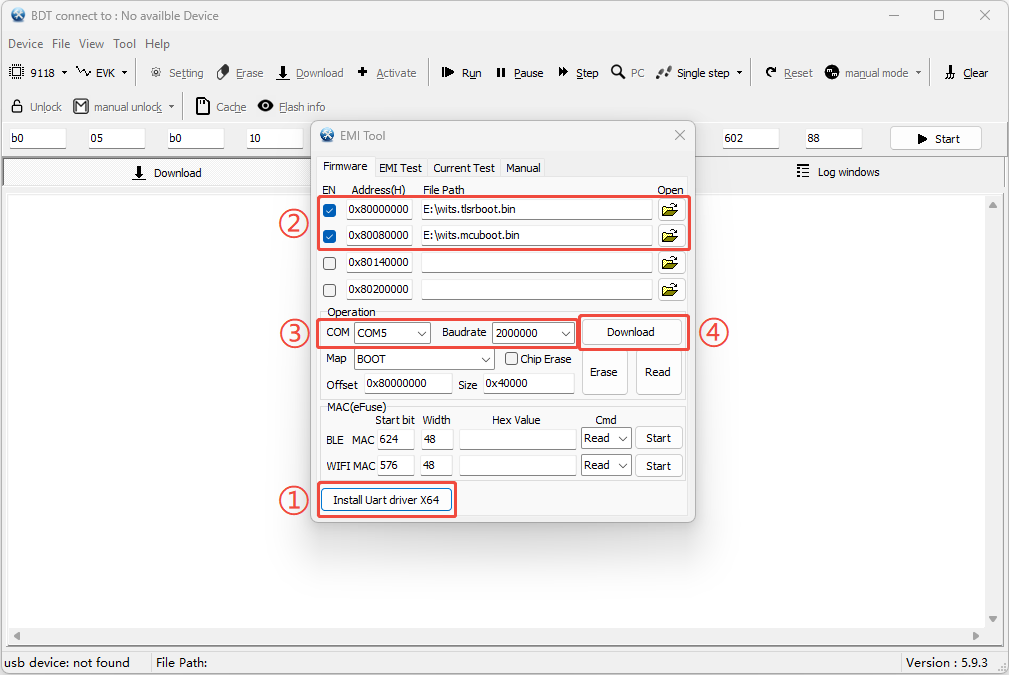
2. Click Install Uart driver X64 and complete the installation wizard for the UART driver. This step is required only for the first installation.
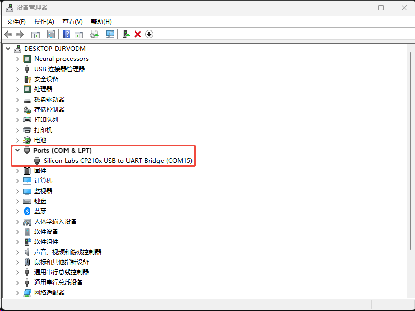
After the driver installation is complete, open the Device Manager. In the Ports (COM & LPT) list, the Silicon Labs CP210x USB to UART Bridge (COMx) will appear as shown in the figure below, indicating that the driver has been installed successfully.
3. On the Firmware page of the EMI Tool:
(1) For the 0x80000000 address, click the folder icon and select the wits.tlsrboot.bin.
(2) For the 0x80080000 address, click the folder icon and select the wits.mcuboot.bin.
(3) In the Operation section, select the COM port corresponding to the development board and set the baud rate to 2,000,000 bps.
(4) Click the Download button to start flashing. After flashing completes, the development board restarts automatically.
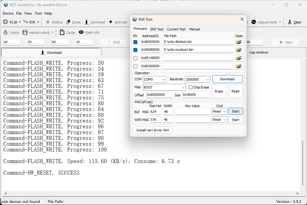
After flashing completes, the BDT interface displays the following log:
1. Configure the serial port permissions:
To support firmware flashing and CLI command transmission through the serial port, add the current user to the dialout group:
sudo usermod -aG dialout $USER
After running the command, you need to log out and log in again for the permission to take effect.
2. Double-click the TGui file to open the BDT software.
3. Click the 9118 BDT option at the top.
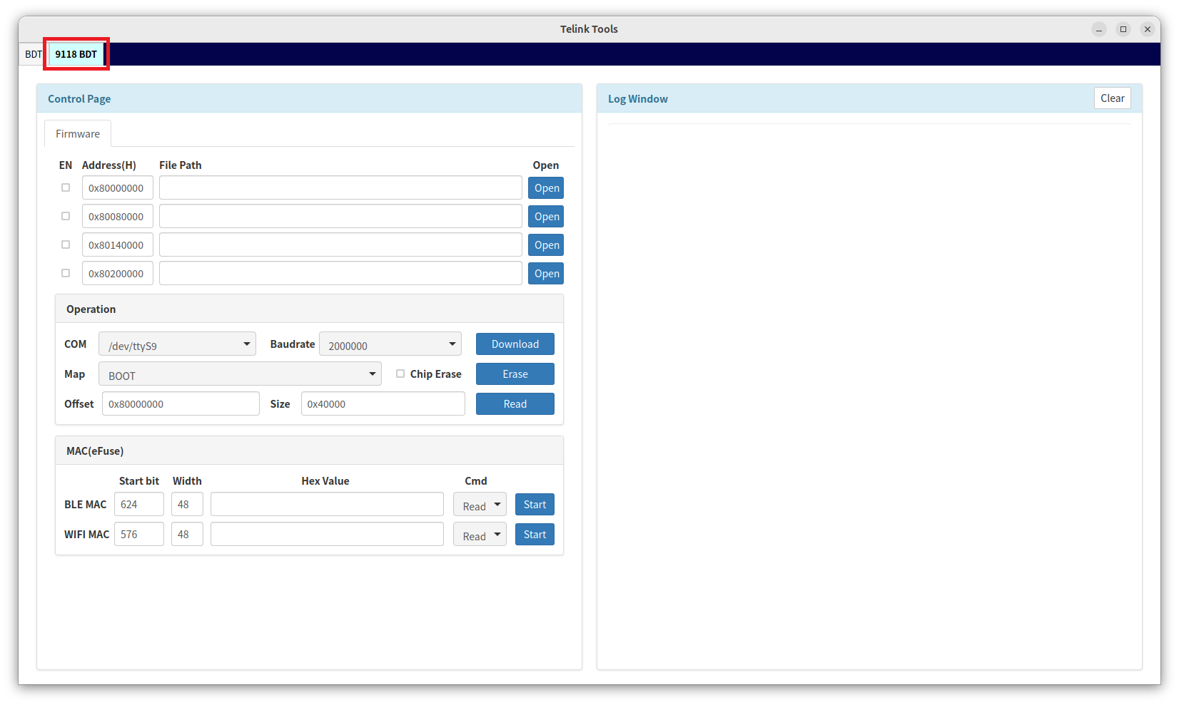
4. In the Firmware section:
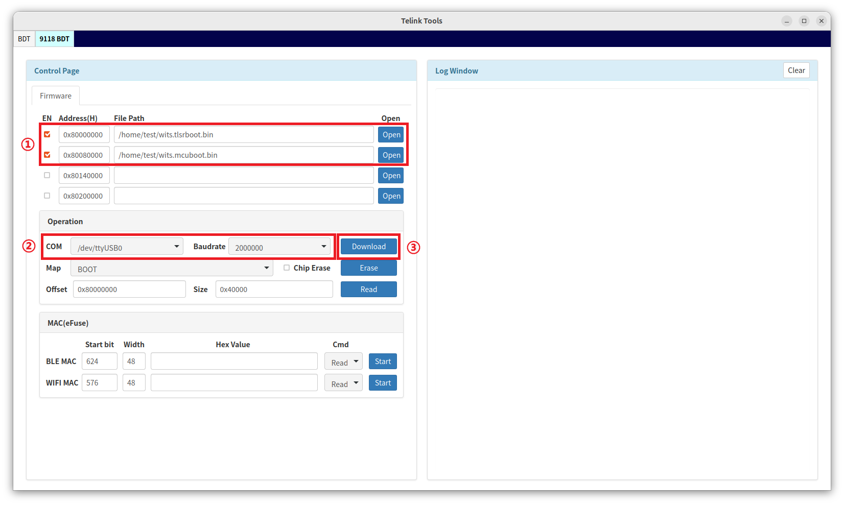
- For the 0x80000000 address, click Open and select the wits.tlsrboot.bin (bootloader).
- For the 0x80080000 address, click Open and select the wits.mcuboot.bin (main firmware).
5. In the Operation section, select the serial port device corresponding to the development board (e.g., /dev/ttyUSB0) and set the baud rate to 2,000,000.
Info
- Run the following command in the terminal to list all USB serial port devices.
ls /dev/ttyUSB*
- If multiple devices exist, you can determine the serial port corresponding to the current device by comparing the list before and after connecting the development board.
6. Click the Download button to start flashing. After flashing completes, the development board restarts automatically.
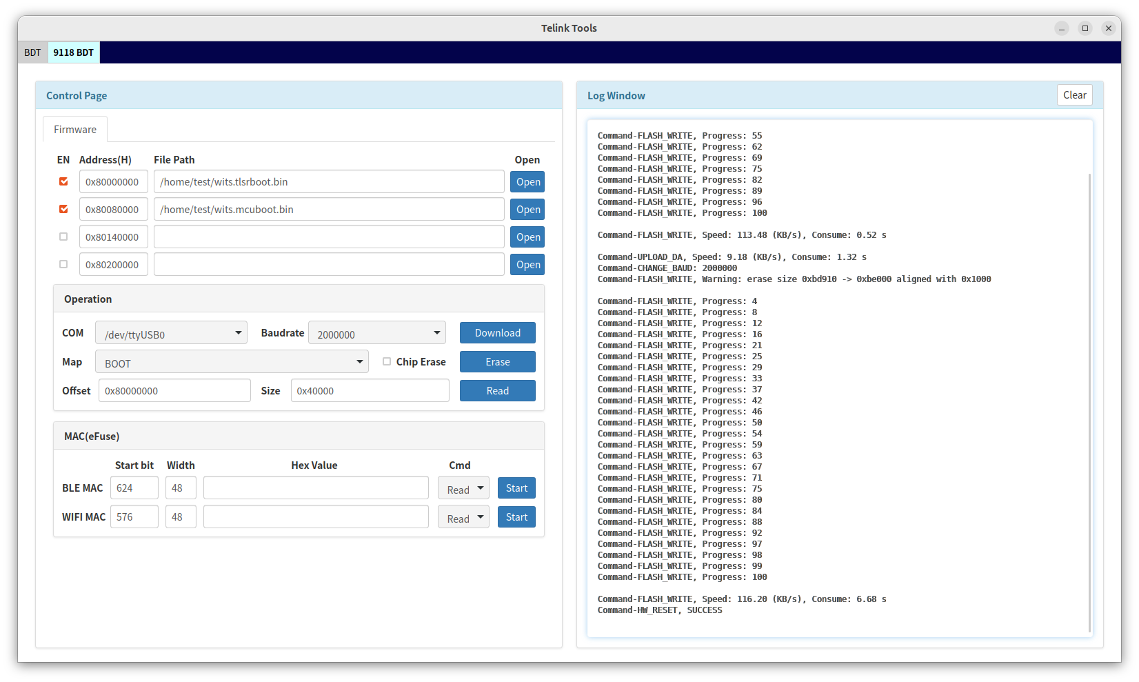
The BDT log after flashing completes is as follows:
Verify the running results
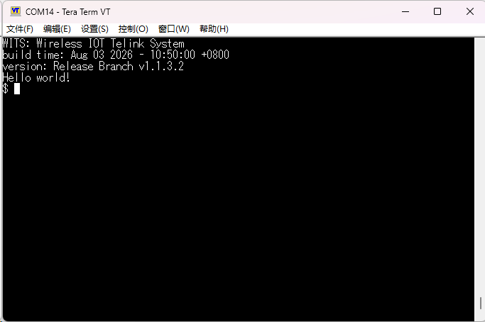
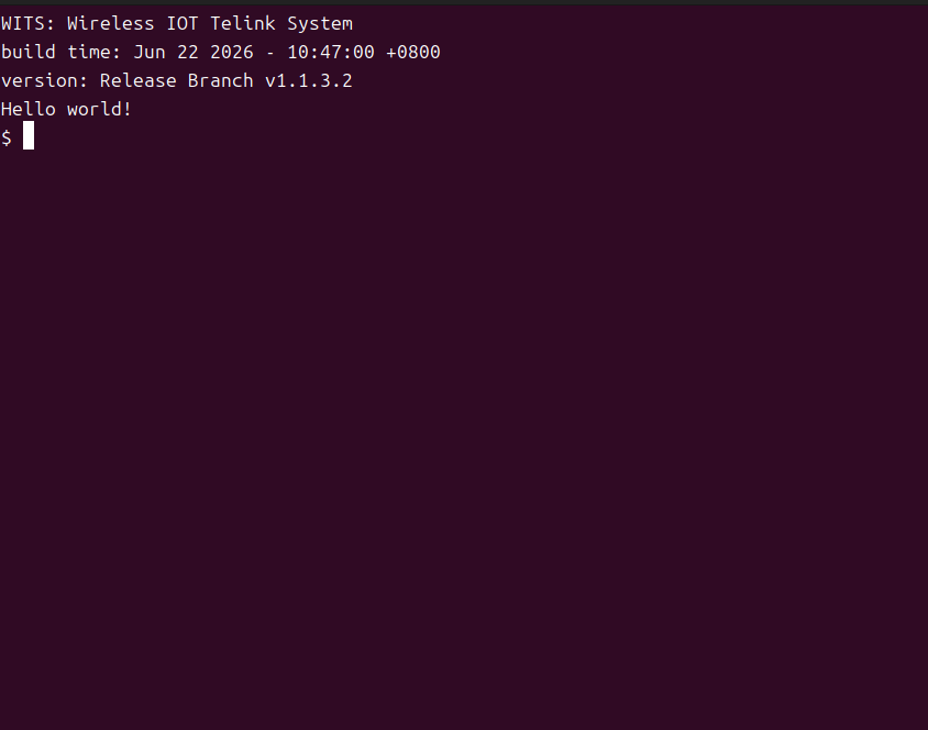
Open the serial port corresponding to the development board using a serial port tool, and set the baud rate to 115,200 bps. Press the RST button on the development board to restart it. After startup completes, confirm whether the serial port tool outputs the Hello world! message to verify the running result.
Info
- The following uses Tera Term (Windows) and minicom (Linux) as examples for detailed instructions. You can also choose other serial port tools based on your habits, but the baud rate must be set to 115,200 bps.
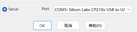
1. Open the Tera Term tool. In the new connection window that pops up, select Serial, and in the Port dropdown list select the COM port where the development board is located (you can check the port of the CP210x device in "Ports (COM & LPT)" in Device Manager), then click OK.
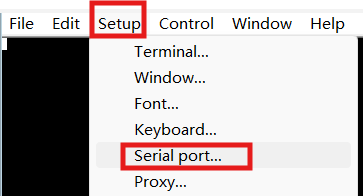
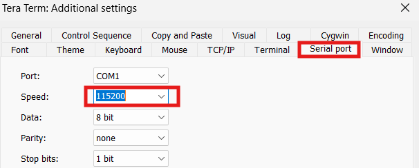
2. Click Setup, select Serial port..., and select the baud rate as 115,200.
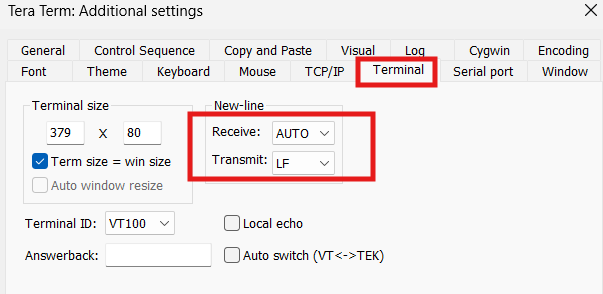
3. Switch to the Terminal page, and set Receive to AUTO and Transmit to LF.
4. Press the RST button on the development board (for the button location, refer to the red box in Hardware connection diagram). The development board restarts automatically.
After the restart completes, if the serial port information shown below is output on the Tera Term page, the example program has run successfully.
1. Enter the following command in the terminal to install minicom:
sudo apt install minicom
2. Open the serial port:
minicom -D /dev/ttyUSB0 -b 115200
Note
- Replace /dev/ttyUSB0 in the terminal command above with the serial port actually corresponding to the device.
3. Set automatic line wrapping and carriage return characters (recommended):
To make it easier to view the serial output, it is recommended to enable minicom's line wrap and carriage return features:
-
Press Ctrl+A, then W, to toggle Line Wrap. When enabled, output exceeding the line width is automatically wrapped instead of being truncated.
-
Press Ctrl+A, then T, to toggle Add Carriage Return. When enabled, the terminal automatically appends a carriage return \r when it receives a line feed \n, avoiding a "staircase" misalignment in the output.
4. Press the RST button on the development board to restart it.
After the restart is complete, if the serial terminal displays the information shown below, the example application is running successfully.
Related reference documents
After successfully running the first example, you can read the following documents next.
| Goal | Document to read |
|---|---|
| Learn Wi-Fi function development | Software Development Guide |
| Learn peripheral driver development | Device Driver Development Guide |
| Learn low-power development | Low Power Development Guide |
| Learn OTA firmware update | Device Firmware Update Guide |
| Learn AT commands | AT Commands |
| View version changes | Release Notes |
Appendix 1: Frequently Asked Questions
Flashing failed
Possible cause: The serial port is selected incorrectly, or the UART driver is not installed correctly.
Solution:
-
Check whether the USB cable is connected properly and whether the LED next to the RST button is lit.
-
Confirm that the correct COM port is selected in BDT.
-
Open BDT -> EMI Tool, and click the Install Uart driver X64 button to reinstall the required driver.
-
Check whether the USB cable is connected properly and whether the LED next to the RST button is lit.
-
Confirm that the correct COM port is selected in BDT.
No serial output or abnormal output
Possible cause: The serial terminal parameters are set incorrectly, or the firmware is not flashed correctly.
Solution:
-
Confirm the serial port is correct and the baud rate is 115,200.
-
Perform the flashing process again and confirm the flashing log shows success.
-
Manually reset the development board after flashing completes.
-
Adjust the serial communication settings of the serial terminal software. Ensure that Receive is set to AUTO and Transmit is set to LF on the Terminal configuration page, as shown below:
-
Confirm the serial port is correct and the baud rate is 115,200.
-
Check the terminal parameters: 8 data bits, 1 stop bit, no parity, no hardware flow control (press Ctrl+A+Z to open the help menu, or press Ctrl+A+O to enter the configuration interface).
-
Disable Hardware Flow Control to avoid data transmission interruptions caused by the development board not being connected to flow control lines.
-
Perform the flashing process again and confirm the flashing log shows success;
-
Manually reset the development board after flashing completes.
Build failed: toolchain not found (Linux)
Possible cause: The toolchain may not be configured correctly.
Solution: Check the /opt/nds32le-elf-mculib-v5/ directory and ensure that its contents are as shown below.
Appendix 2: Download the Telink VS Code Extension auxiliary tools
Take MenuConfig as an example:
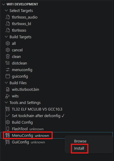
1. Click the T icon in the left sidebar of VS Code and expand the WIFI DEVELOPMENT tree menu.
2. Under the Tools and Settings list, select MenuConfig, right-click it, and click Install in the pop-up menu.
After the installation is complete, a notification indicating successful installation appears in the lower-right corner of the VS Code window.

Info
- After the installation is complete, click menuconfig in the Build Targets list to invoke the tool in VS Code.