Telink BLE Channel Sounding Getting Started
Overview
This document helps you quickly flash the firmware and verify the functionality of the Telink Channel Sounding (CS) example project. Channel Sounding is a high-accuracy ranging feature of Bluetooth Low Energy (BLE).
This example provides two firmware files, one for each device role at either end of a ranging link:
telink_TL721x_initiator_demo_V1.0.0.bin: the initiator firmware, which initiates rangingtelink_TL721x_reflector_demo_V1.0.0.bin: the reflector firmware, which works with the initiator to complete ranging
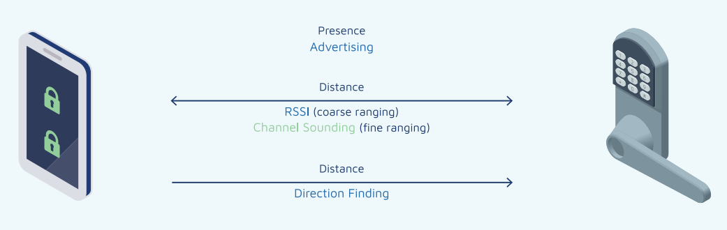
Flash the firmware to two development boards respectively, then use the host software CS_Tool to complete pairing quickly and display ranging results in real time as a line chart.
Verification flow: Hardware and software preparation → Install BDT → Connect the hardware → Flash the firmware → Functional verification. See the sections below for details.
Hardware and software preparation
Hardware checklist
Table 2.1 Hardware checklist
| Hardware | Model or specification | Quantity | Description |
|---|---|---|---|
| PC | Windows 10 or 11 | 1 | Development host for the flashing software, the host software CS_Tool, and so on. |
| Development board | Telink development board supporting Channel Sounding | 2 | One board acts as the initiator, the other as the reflector. This document uses the TL721x custom board C1T314A102. |
| Programmer | Telink programmer (TLSRGSOCBK56B) | 1 | Flashes the firmware to both development boards. |
| Cables | USB Type-C cable, Dupont wires | Several | Powers the boards, carries serial data, and connects the programmer to the boards. For wiring details, see Connect the hardware. |
Telink also offers dual-antenna custom development board options (TL322x custom board C1T382A102, TL323x custom board C1T395A102 and so on). Please contact us for selection guidance.
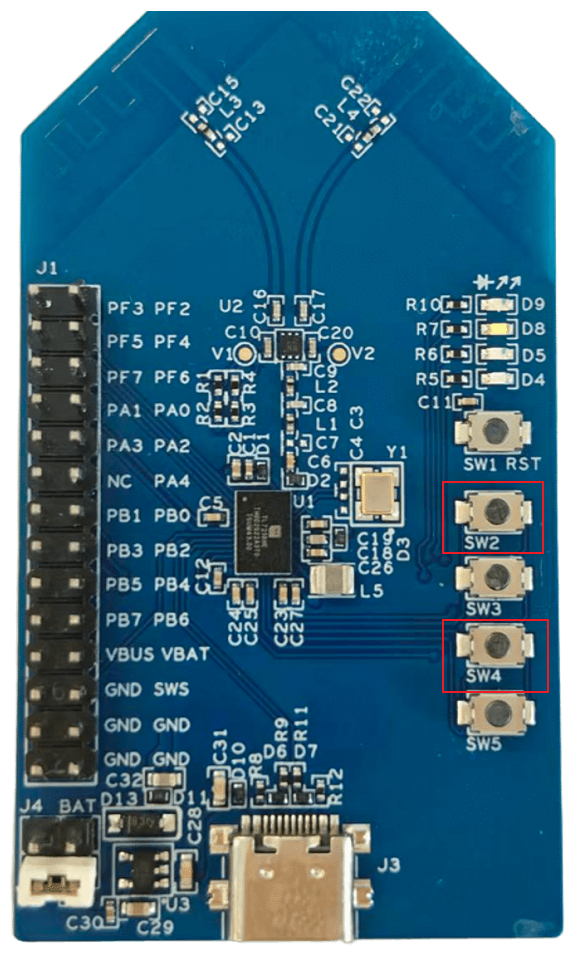
The TL721x custom development board is shown below:
Software and firmware checklist
Table 2.2 Software and firmware checklist
| Software or firmware | Name | Description |
|---|---|---|
| Flashing tool | Burning and Debugging Tool (BDT) | Dedicated flashing and debugging tool for writing firmware to the development board. It provides the CS_Tool host software (menu Tool → CS_Tool). See Install BDT. |
| Host software | CS_Tool | Quickly pairs the initiator with the reflector and displays Channel Sounding distance values in real time as a line chart. |
| Prebuilt firmware | telink_TL721x_initiator_demo_V1.0.0.bin, telink_TL721x_reflector_demo_V1.0.0.bin |
Initiator firmware and reflector firmware. |
Note
To get the prebuilt firmware, click Download.
Install BDT
BDT is a portable flashing and debugging tool from Telink for writing firmware to the target chips.
-
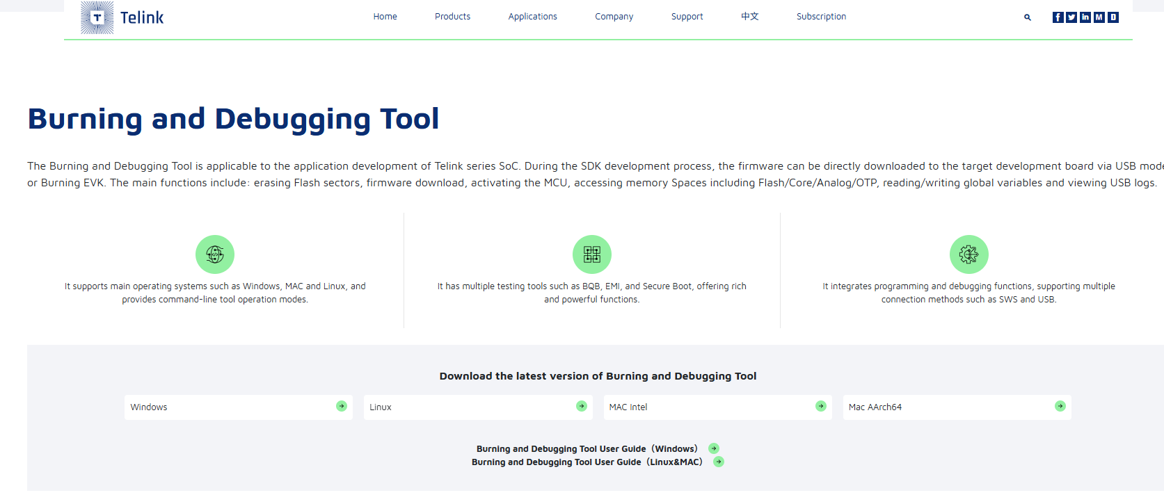
Download BDT: visit Telink Developer Center - Development Tools and download the package for your operating system.
-
Extract and run (Windows example):
-
Extract the package to a custom path, for example C:\Telink\BDT.
-
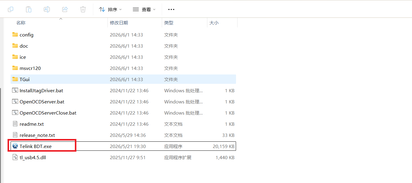
Go to the release directory, for example C:\Telink\BDT\release_v5.9.2.
-
Double-click Telink BDT.exe to launch the tool.
-
-
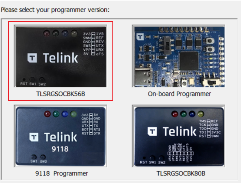
Select the programmer version: BDT supports several programmer versions. Select the one that matches your chip series. This example uses the Telink programmer (TLSRGSOCBK56B).
Flashing procedure
Flash different firmware to each development board: telink_TL721x_initiator_demo_V1.0.0.bin for the initiator and telink_TL721x_reflector_demo_V1.0.0.bin for the reflector.
Connect the hardware
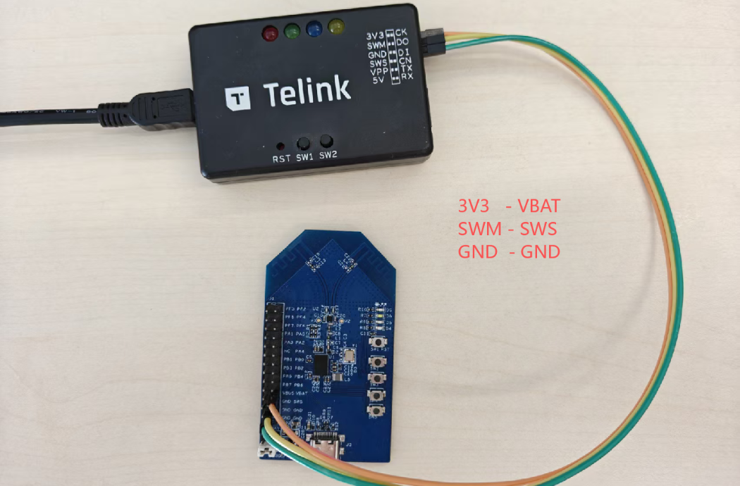
Before using BDT, connect the PC, programmer, and development board as follows:
- PC ↔ programmer: connect with a USB cable. If the green LED on the programmer stays on, the programmer is recognized by the PC.
-
Programmer ↔ development board: connect with Dupont wires:
-
Power: 3V3 ↔ VBAT; GND ↔ GND
-
Data: SWM ↔ SWS (Swire)
-
Flash the firmware
Connect one development board at a time. The steps are the same for both boards; only the selected firmware differs.
-
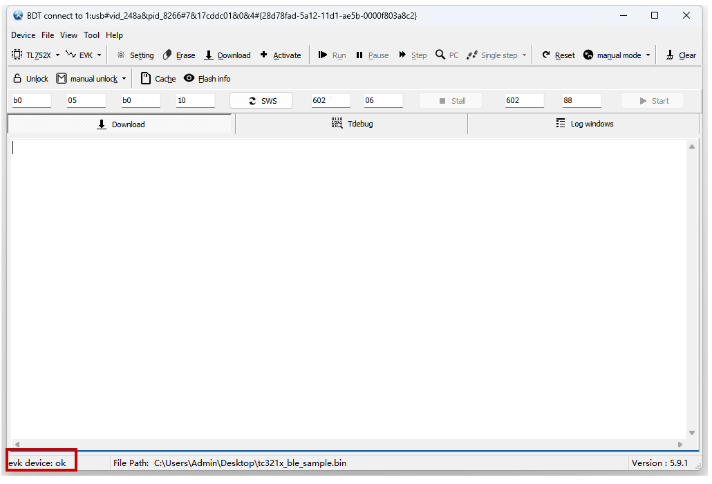
Connect the programmer: open BDT. Before flashing, make sure the tool has detected the programmer, as shown below.
- If BDT does not find the device, click Device → Refresh to view available devices.
- If BDT finds multiple devices, all of them are listed. The first is active by default; you can also switch the target device in the list.
-
Configure and flash:
-
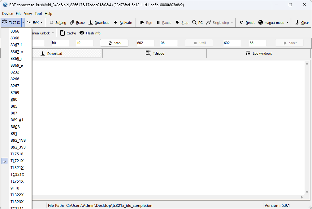
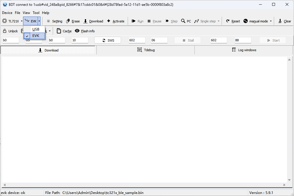
Select the chip series: in the chip drop-down list at the top, select TL721x.
-
Select the download mode EVK.
-
Set the download address: click Setting, switch to the Flash tab, and set the start offset in Download Addr. The default value is
0x000000.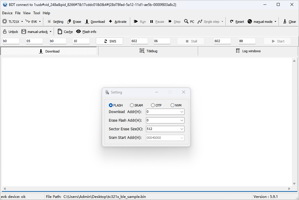
-
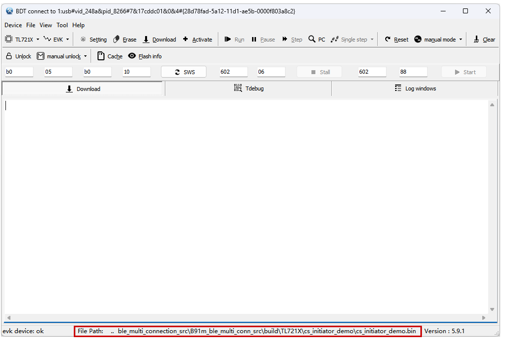
Load the firmware: click File → Open/Reopen and select the
.binfile (initiator:telink_TL721x_initiator_demo_V1.0.0.bin; reflector:telink_TL721x_reflector_demo_V1.0.0.bin). After loading, the full file path appears at the bottom of the main window.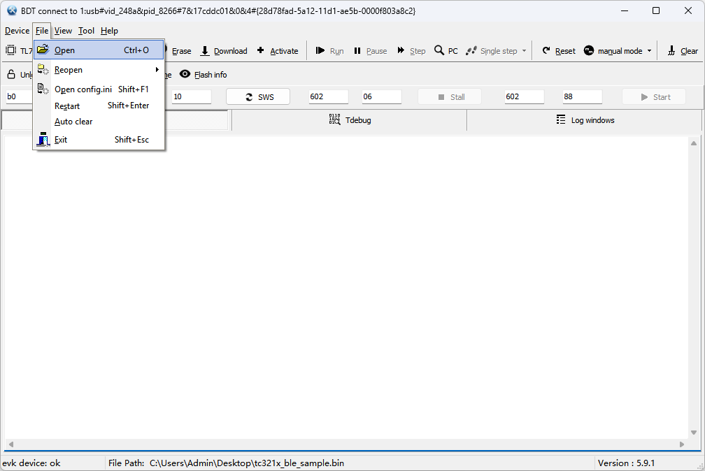
-
Check the connection between the development board and the PC.
- If the connection is normal, evk device: ok appears at the bottom left of the main window.
- If the board is not connected properly, usb device: not found appears at the bottom left.
-
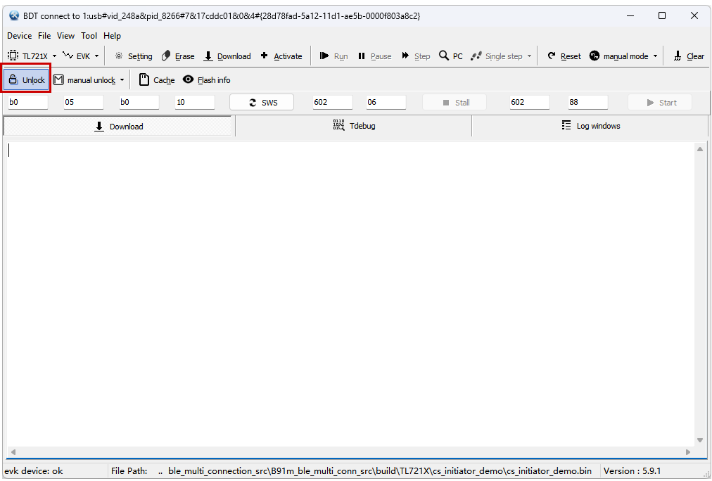
Unlock Flash: click Unlock or select auto unlock to remove Flash write protection. If Flash is write-protected, flashing fails.
-
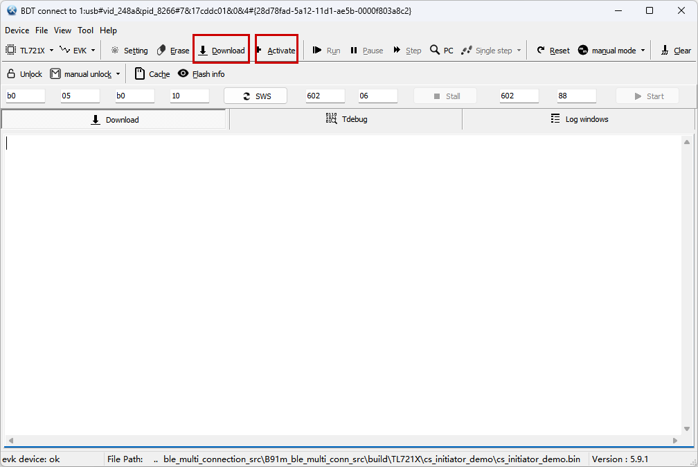
Flash the firmware: click Activate, then Download, and wait for the log window to report success.
-
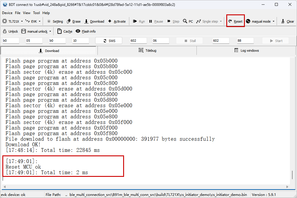
Reset and run: if the reset mode is auto mode, the board resets automatically after flashing. If it is manual mode, click Reset after flashing.
-
Functional verification
Reconnect and power on the hardware
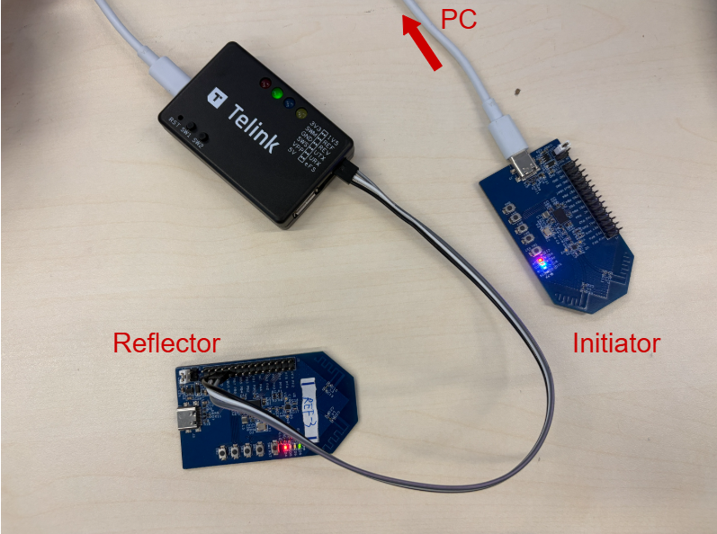
After flashing, power both development boards on again. The blue LED on the initiator and the green LED on the reflector blink.
Connect the initiator directly to the PC with a USB Type-C cable. The on-board USB-to-serial bridge exposes a COM port to CS_Tool. Power the reflector over USB Type-C or from the 3V3 pin of the Telink programmer. The initiator sends ranging results and logs to CS_Tool over the serial port.
Open CS_Tool
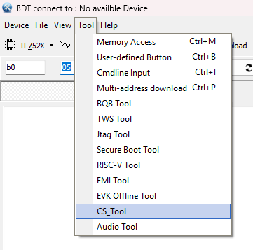
Open Telink BDT, click Tool on the menu bar, and select CS_Tool from the drop-down menu.
Connect the device
-
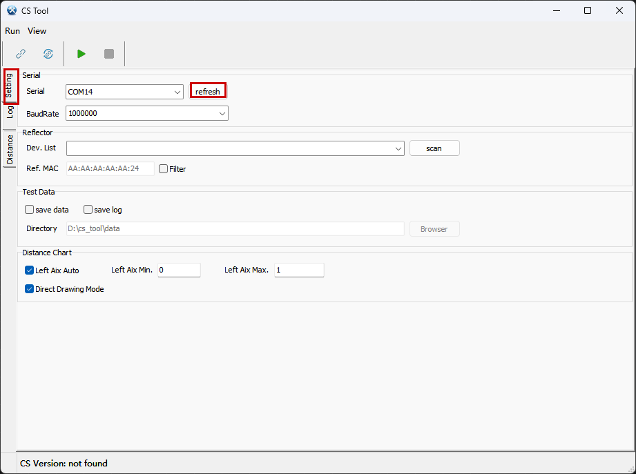
Open CS_Tool, click the Settings tab on the left, select the COM port in the Serial section (click refresh if no port is listed), and set the baud rate to 1000000.
-
Press the PAIR (SW2) button on the initiator to start pairing. The initiator scans for and connects to the device named cs_telink. When connected, the red LEDs on both boards stay on and the initiator starts ranging automatically.
Note
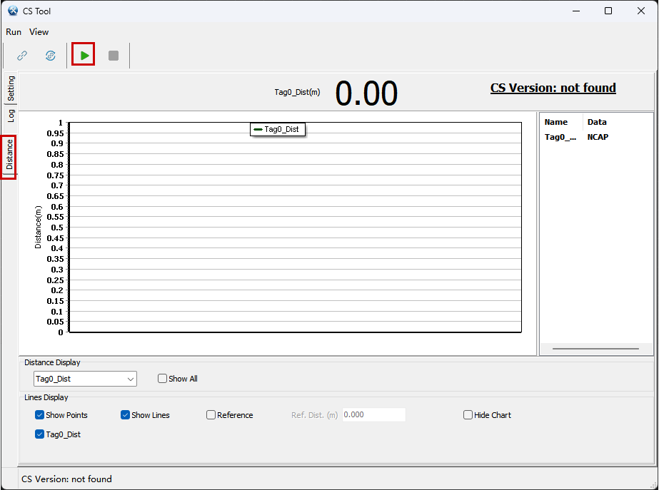
When using CS_Tool for the first time, make sure Left Aix Auto and Direct Drawing Mode are selected.
Start ranging and display data
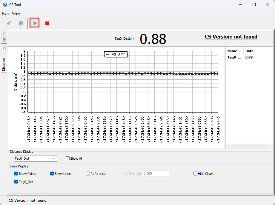
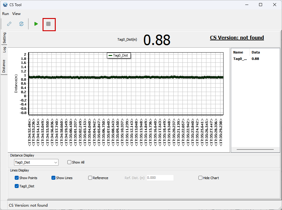
- Click the Distance tab to view ranging results in real time.
- Click Start to record results and display the distance-time line chart.
Stop ranging and reconnect
-
Click Stop at the top to stop recording data.
-
After a power cycle, the initiator reconnects to the paired device automatically and starts ranging.
- To delete the pairing information, press the UNPAIR (SW4) button on the initiator. The red LED turns off and the initiator no longer reconnects automatically.
Usage notes
The reflector returns ranging data to the initiator over the Ranging Service (RAS) / Ranging Profile (RAP). Under strong interference, data transmission may fail and be retried repeatedly, causing ranging stalls. To optimize the software configuration, increase the CS Procedure Interval, suitably reduce the number of CS Procedure channels, or increase the maximum number of Ranging Data entries buffered by the initiator.
For optimization for specific scenarios or related requirements, please contact us.
Appendix A: FAQ
Flashing failure
BDT cannot detect the programmer:
- Check the connection between the programmer and the PC, and replug the programmer.
- In BDT, click Device → Refresh to refresh the device list.
- Make sure the correct chip series is selected.
Example runtime issues
COM port not detected:
- Make sure the initiator is connected directly to the PC with a USB Type-C cable.
- Click refresh on the Settings tab of CS_Tool to refresh the port.
Pairing failure:
- Make sure both development boards are flashed with the correct firmware and powered on (blue LED blinking on the initiator, green LED blinking on the reflector).
- Make sure the PAIR (SW2) button on the initiator has been pressed to enter pairing mode.
- To re-pair, press the UNPAIR (SW4) button on the initiator to delete the old pairing information, then press PAIR again.
Ranging stalls:
- Check whether the environment has strong interference. Move the boards or change the test scenario.
- See the software configuration options in Usage notes.
Appendix B: Community and resources
Table B.1 Community and resources
| Resource | Description |
|---|---|
| Telink official forum | Technical discussion and support |
| Telink official website | Product information |
| Telink documentation site | Documentation center |